Determination of resistance of contact connections of cables and busbars
To simplify calculations, I neglect the resistance of contact connections of cables and busbars, due to the almost imperceptible effect on short-circuit currents.
If you use the resistance values of contact connections of cables and busbars in your TKZ calculation, then they are accepted according to Appendix 4 of Table 17.18 GOST 28249-93.
When approximately taking into account the contact resistances, the following is accepted:
- rk = 0.1 mOhm - for contact cable connections;
- rк = 0.01 mOhm - for busbars.
Determination of bus resistances
3.1 We determine the inductive reactance of aluminum rectangular buses of type AD31T with a cross section of 50x5 using expression 2-12 [L1. With. 29]:
3.1.1 Determine the average geometric distance between phases 1, 2 and 3:
3.2 Using Table 2.6, we determine the active linear resistance for an aluminum bus with a cross-section of 50x5, where rsp. = 0.142 mOhm/m.
To simplify calculations, the resistance values of busbars and busbars can be used from tables 2.6 and 2.7 [L1. With. 31].
3.3 Determine the busbar resistance, taking into account the length from the TM-400 transformer to RU-0.4 kV:
Content
- 1. Determination of the resistance of the power supply system
- 2. Determination of transformer resistance 6/0.4 kV
- 3. Determination of bus resistance
- 4. Determination of cable resistance
- 5. Determination of current transformer resistances
- 6. Determination of resistance of circuit breakers
- 7. Determination of resistance of contact connections of cables and busbars
- 8. Determination of three-phase short circuit current. at the end of the cable line
- 9. References
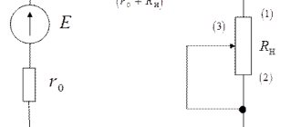
In this example, we will consider the calculation of the three-phase short circuit current in a 0.4 kV network for the circuit shown in Fig. 1.
Initial data:
1. The short circuit current at the HV terminals of the 6/0.4 kV transformer is 11 kA.
2. Supply transformer type TM - 400, the main technical characteristics are accepted according to technical specifications. information on the transformer:
- rated power Sn.t - 400 kVA;
- rated voltage of the HV winding Un.t.HV – 6 kV;
- rated voltage of the LV winding Un.t.LV – 0.4 kV;
- short-circuit voltage Uк – 4.5%;
- short-circuit loss power in transformer Rk – 5.5 kW;
- group of winding connections according to GOST 11677-75 – Y/Yn-0;
3. The transformer is connected to a 400 V assembly, with aluminum busbars of type AD31T in accordance with GOST 15176-89 with a cross-section of 50x5 mm. The tires are located in the same plane - vertically, the distance between them is 200 mm. The total length of the busbars from the transformer terminals to the QF1 input circuit breaker is 15 m.
4. On the 0.4 kV side, an input circuit breaker of type XS1250CE1000 for 1000 A (from SOCOMEC) is installed, on the outgoing lines there are automatic circuit breakers of type E250SCF200 for 200 A (from SOCOMEC) and current transformers of type TCA 22 200/5 with accuracy class 1 ( SOCOMEC company).
5. The cable line is made of aluminum cable brand AVVGng with a cross section of 3x70+1x35.
Solution
In order to calculate short-circuit currents, we must first draw up an equivalent circuit, which consists of all the resistances of the short-circuit circuit, after which we determine all the resistances included in the short-circuit circuit. Active and inductive resistances of all elements of the equivalent circuit are expressed in milliohms (mOhm).
Determination of the resistance of the power supply system
In practical calculations, to simplify the calculations of short-circuit currents. Only the inductive reactance of the power system is taken into account, which is equal to the total. Active resistance is not taken into account, these simplifications do not affect the accuracy of calculations!
1.1 We determine the resistance of the power system from the HV side using expression 2-7 [L1. With. 28]:
1.2 We determine the resistance of the power system reduced to a voltage of 0.4 kV using expression 2-6 [L1. With. 28]:
Determination of current transformer resistances
The values of the active and inductive resistances of the windings for one current transformer type TSA 22 200/5 with accuracy class 1 are determined according to Appendix 5, Table 20 of GOST 28249-93, respectively, rta = 0.67 mOhm, xta = 0.42 mOhm.
The active and inductive resistance of single-turn transformers (for currents more than 500 A) can be neglected when calculating short-circuit currents.
According to [L1. With. 32] to simplify calculations, the resistance of current transformers is not taken into account due to the almost imperceptible effect on short-circuit currents.