If you look at the printed circuit board of even the simplest electronic device, you will definitely see a capacitor, and most often you will see many of these elements. The presence of these products in various electronic circuits is explained by the properties of these radioelements and the wide range of functions that they perform.
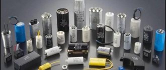
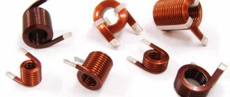
Currently, the industry supplies the market with capacitor products of various types (Fig. 1). Product parameters vary widely, which makes it easy to select a radio component for a specific purpose.
Rice. 1. Common types of capacitors
Let's take a closer look at the designs and basic parameters of these ubiquitous radioelements.
What is a capacitor?
In the classical sense, a capacitor is a radio-electronic device designed to accumulate the energy of an electric field, having the ability to accumulate an electric charge, with the subsequent transfer of the accumulated energy to other elements of the electrical circuit. The devices are very often used in various electrical circuits.
Capacitors are capable of accumulating charge very quickly and just as quickly releasing all the accumulated energy. Their work is characterized by the cyclical nature of this process. The amount of accumulated electricity and the periods of charge-discharge cycles are determined by the characteristics of the products, which in turn depend on the type of model. The parameters of these quantities can be determined by the product labeling.
Device
Capacitor - what is it for, device and principle of operation
The simplest capacitor device includes the following components:
- The body is cylindrical;
- Two plates – two strips of conductive material (aluminum or copper foil) rolled into a roll;
- A layer of dielectric (paper) between the plates;
- Two electrodes soldered to the plates and used to connect the device to the electrical circuit.
How does a simple capacitor work?
Design and operating principle
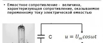
The simplest capacitor is two metal plates separated by a dielectric. The air space between the plates can act as a dielectric. A model of such a device is shown in Fig. 2.
Rice. 2. Model of the simplest capacitor device
If a constant voltage is applied to the structure, a short-term closed electrical circuit is formed. Charges will be concentrated on each metal plate, the polarity of which will correspond to the polarity of the applied current. As charges accumulate, the current will weaken, and at a certain point the circuit will break. In our case, this will happen at lightning speed.
When a load is connected, the accumulated energy will flow through the load element in the opposite direction. There will be a short-term surge of electric current in the formed circuit. The amount of accumulated charges (capacity, C) directly depends on the size of the plates.
The unit of measurement of capacitance is usually called the farad (F). 1 F is a very large value, so in practice multiple values are often used: microfarads (1 μF = 10-6 F), nanofarads (1 nF = 10-9 F = 10-3 μF), picofarads (1 pF = 10-12 F = 10-6 µF). The milifarada value is very rarely used (1 mF = 10-3 F).
The designs of modern capacitors differ from the model we are considering. In order to increase the capacity, instead of plates, plates made of aluminum, niobium or tantalum foil separated by dielectrics are used. These puff strips are tightly rolled into a cylinder and placed in a cylindrical housing. The principle of operation is no different from that described above.
There are also flat capacitors, structurally consisting of many thin plates, pressed between layers of dielectric in the shape of a parallelepiped. Such models can be imagined as a stack of plates, forming many pairs of plates connected in parallel.
The following are used as dielectrics:
- paper;
- polypropylene;
- Teflon;
- glass;
- polystyrene;
- organic synthetic films;
- enamel;
- barium titanite;
- ceramics and various oxide materials.
A separate group consists of products in which one lining is made of metal, and the second is an electrolyte. This is a class of electrolytic capacitors (example in Figure 3 below). They differ from other types of products due to their large specific capacity. Oxide semiconductor models have similar properties. Their second anode is a semiconductor layer deposited on an insulating oxide layer.
Rice. 3. Design of radial electrolytic capacitor
Electrolytic models, as well as most oxide semiconductor capacitors, have unipolar conductivity. Their operation is permissible only if there is a positive potential at the anode and at rated voltages. Therefore, the polarity of connecting the mentioned radio-electronic elements should be strictly observed.
The polarity must be indicated on the body of such a device (a light strip with “–” signs, see Fig. 4) or the “+” sign on the side of the positive electrode on the cases of old domestic capacitors.
Figure 4. Pin polarity designation
The life of the electrolytic capacitor is limited. These devices are very sensitive to high voltages. Therefore, when choosing a radio element, try to ensure that its operating voltage is significantly higher than the rated voltage.
Story
The prototype of the modern capacitor was constructed in 1745 simultaneously by two scientists: the Dutch physicist Pieter van Musschenbroek and the German Lutheran cleric Ewald Jürgen von Kleist. The first called his invention the “Leyden jar”, the second – a medical jar. The similarity in the names was not accidental - the device, both German and Dutch, was a glass jar with two tin plates located on its outer and inner surfaces, with a dielectric plug inserted into the neck, which was pierced by a metal rod with a chain. Such a device was charged from an electrophore machine, which was very popular in those days. The charge accumulated on the plates was small - no more than 1 microcoulomb.
Invented in 1745, “banks” remained virtually unchanged over the next 200 years. Only in the mid-50s of the 20th century, during the active development of the production of various radio components, the first storage devices of relatively small sizes began to be produced. At the same time, they began to be used in various household appliances, electric tools, and later – computers.
For your information. Modern radio components of this type have a wide variety of shapes, sizes and characteristics: from the largest and most powerful ionistors to small drives used in computer printed circuit boards and in household appliance controllers.
"Leyden jar" and modern charge storage
Properties
From the description it is clear that for direct current the capacitor is an insurmountable barrier, except in cases of dielectric breakdown. In such electrical circuits, a radio element is used to accumulate and store electricity on its electrodes. A change in voltage occurs only in cases of changes in the current parameters in the circuit. These changes can be read and acted upon by other circuit elements.
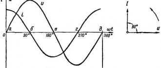
In sinusoidal current circuits, a capacitor behaves like an inductor. It passes alternating current, but cuts off the direct component, which means it can serve as an excellent filter. Such radio-electronic elements are used in feedback circuits, included in oscillatory circuit circuits, etc.
Another property is that variable capacitance can be used to shift phases. There are special starting capacitors (Fig. 5) used to start three-phase electric motors in single-phase electrical networks.
Rice. 5. Start capacitor with wires
Capacitor in electric current circuits
So, we roughly understand what a capacitor is, but we haven’t really figured out how this element works yet.
DC circuit
In simple words, a capacitor, or “conder”, as it is popularly called, is a small element that, like a battery, is capable of accumulating a certain charge, which it is ready to discharge in a matter of seconds
Interesting to know! Unlike a battery, there is no source of EMF in a capacitor.
In order for the conductor to discharge, it needs to close the contacts directly or through a circuit. It seems that everything is clear, but how does the current flow in the capacitor when it is connected to the network?
- Let's start with direct current and conduct one small experiment. To do this, we need the capacitor itself, a 12-volt DC source and a light bulb with wires, also 12 volts.
All elements are assembled in a chain
- We connect all this together, as shown in the photo above, and we see that nothing happens - the light does not light.
Connection bypassing the capacitor
- We change the position of the “crocodile” so as to allow current to bypass the capacitor. And, lo and behold! The light came on! Why is this happening?
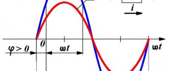
- It's simple, just remember that current flows through a capacitor only when it is charging and discharging, and the voltage will always lag behind the current.
- A discharged capacitor is akin to a short circuit in the circuit - when it is connected to a voltage source, at the first moment of time there is no voltage in it, but there is a current, which at this moment in time is maximum (that's the lag).
- Current flows through the capacitor, and it begins to accumulate charge, increasing its internal voltage until it is equal to the voltage of the power source and the capacitor fills its entire capacity.
- At this point in time, the current stops flowing, and since the capacitor cannot discharge, then, accordingly, the light bulb will not light.
- This process can be compared with a water system in the form of a communicating vessel, separated by a valve, with one part empty and the other full. Remove the obstacle, and water will flow into the second vessel until the pressures equalize, that is, the pressure drops to zero.
- What would happen if the capacitor were disconnected from the circuit and shorted? Yes, everything is the same! At the first moment of time, the current will be maximum at a constant voltage. The current will run forward, and the voltage will follow it, until all the charge is gone.
- Again, as an example, we take a water system consisting of a full tank, which will act as a condenser, and a faucet on it through which water can be drained. We open the tap and see that water immediately flows, while the pressure (voltage) will drop smoothly as the container is emptied.
The same patterns are characteristic of sinusoidal current, which we will talk about now.
Main parameters and characteristics
Capacity.
An important parameter of a capacitor is its nominal capacity. For a flat capacitor the formula is valid:
С = (ε*ε 0 *S) / d,
where ε is the dielectric constant of the dielectric, S is the dimensions of the plates (plate area), d is the distance between the plates (plates).
The actual capacity of individual elements is usually small, but you can get a structure with a capacity of several farads if you connect a huge number of plates in parallel. In this case, the real capacity is equal to the sum of all the capacitances of the plates.
The maximum capacitance of some capacitors can reach several farads.
Specific capacity.
A value characterizing the ratio of capacity to volume or mass of a radio component. This parameter is important in microelectronics, where the dimensions of the parts are very important.
Rated voltage.
One of the important electrical characteristics is the rated voltage - the value of the maximum voltages at which the capacitor can operate without losing the values of its other parameters. When a critical value equal to the breakdown voltage is exceeded, the dielectric is destroyed. Therefore, the rated voltage is chosen to be obviously greater than any possible maximum amplitudes of the sinusoidal current in the capacitor circuit.
There are characteristics, such as loss tangent, temperature coefficient of capacitance, leakage resistance, dielectric absorption, etc., that are of interest only to specialists, and their parameters can be found in special reference books.
Schematic illustration
Externally, it looks like two plates that are separated by a dielectric. The larger the area of the plates used and the closer they are, the higher the capacitance of the capacitor. It was not for nothing that the word “linings” was used at first, because they are not always flat in appearance. Thus, in metal-paper capacitors, aluminum foil acts as a kind of plates, which is rolled together with a paper dielectric into one dense ball (which follows the shape of the metal case). To increase the electrical strength, thin capacitor paper can be impregnated with insulating compounds (for example, transformer oil).
This type of capacitor boasts a capacity of several hundred microfarads. Other members of the family of this electronics component are designed according to a similar principle. How to check the capacitor and make sure that the real state of affairs corresponds to the inscriptions? The easiest way is to use a digital multimeter. An ohmmeter can also answer the question of how to check a capacitor.
Classification
The main parameters of capacitor products are determined by the type of dielectric. The stability of the capacitance, the dielectric loss tangent, the piezoelectric effect and others depend on the material. Based on this, it is advisable to classify models according to the type of dielectric.
Based on this feature, the following types of products are distinguished:
- vacuum;
- with air dielectric;
- radioelements in which the dielectric is liquid;
- with a solid inorganic dielectric (glass, mica, ceramics). Characterized by low leakage current;
- models with paper dielectric and combined, paper-film;
- DC oil capacitors;
- electrolytic;
- category of oxide capacitors, which include oxide semiconductor and tantalum capacitors;
- solid-state, in which an organic polymer or polymerized semiconductor is used instead of a liquid electrolyte.
In solid-state models, the service life is longer than that of liquid electrolytic models and is about 50,000 hours. They have less internal resistance, that is, the ESR is almost independent of temperature, they do not explode.
Products are also classified according to another important parameter - change in capacity. Based on this feature they distinguish:
- permanent capacitors, that is, those that have a constant capacitance;
- variables in which the change in capacitance can be controlled mechanically or using applied voltage (varicaps and variconds), as well as by changing temperature (thermal capacitors);
- a class of tuning capacitors that are used to adjust or equalize working capacitances when setting up circuits, as well as for the purpose of periodically adjusting various circuits.
All existing capacitors can be divided into general and special. General purpose products include the most common low-voltage capacitors (see Fig. 6). There are no special requirements for them.
Rice. 6. General purpose capacitors
All other capacitive radioelements belong to the special purpose class:
- pulse;
- launchers;
- high voltage (see Fig. 7);
- interference suppression
- dosimetric, etc.;
Rice.
7. High-voltage capacitors The devices shown in the photo can operate in high-voltage circuits of relatively low frequency.
Capacity
But whatever the geometry, the relationship does not change - the larger the area of the plates and the thinner the dielectric layer, the greater the capacitance, and vice versa. However, even if the plates are very small, and the distance between them is quite large, a certain capacity is maintained. For example, small capacitors are made directly on a printed circuit board, placing two printed circuit tracks opposite each other.
However, the capacity (as well as its stability, that is, the ability not to discharge) also depends on the dielectric. Any material, even a vacuum, conducts electric current to one degree or another, which leads to a gradual leakage of charge - self-discharge. So you have to strike a balance - between capacity and self-discharge, as well as price, size and other factors. That is why there are many types and types of capacitors - different dielectrics and different plates are used for different, specific operating conditions.
What happens if you use a capacitor with a larger or smaller capacity than required in this case? In most cases, a slight excess of capacity will only be beneficial. But it is not recommended to use a smaller capacity (or, indeed, to greatly exceed it) - this can worsen the performance of the entire device, and the capacitors themselves will not last long.
Editor's clarification
Marking
A letter system was used to label domestic products. Today digital marking is common. The following symbols were used in the alphabetic system:
- K – capacitor;
- B, K, S, E, etc. – type of dielectric, for example: K – ceramic, E – electrolytic;
- In third place was a symbol indicating performance features.
In this marking system, the first letter was sometimes omitted.
In the new marking system, the letter K may appear first, followed by an alphanumeric code. Numbers are used to indicate the denomination, type of dielectric and development number. An example of such marking is shown in Figure 8. Please note that the switching polarity is indicated on the body of the electrolytic capacitor.
- Capacitance from 0 to 999 pF is indicated in picofarads, for example: 250p:
- from 1000 to 999999 pF – in nanofarads: n180;
- from 1 to 999 μF – in microfarads: 2μ5;
- from 1000 to 999999 µF – in millifarads: m150;
- Capacitance greater than 999999 μF is indicated in farads.
The principle of operation of a capacitor using a specific example
When a battery is connected to a capacitor (for example, it could be a Krona battery), charged particles from the battery flow into the capacitor and rush towards each other through the conductors.
But since there is a dielectric between the conductors, they cannot continue their “journey” and remain on the conductors “until required.”
An electric field is formed between negatively and positively charged particles, which holds them together, preventing them from “running away”.
Connection of capacitors
There are two connection methods: parallel and serial. With a parallel connection, the total capacitance is equal to the sum of the capacitances of the individual elements: C total. = С 1 + С 2 + … + С n .
For a series connection, the capacitance calculation is calculated using the formula: Ctot. = ( C1* C2 *…* Cm ) / ( C1 + C2+…+Cn )
To quickly calculate the total capacitance of connected capacitors, it is better to use our calculators:
- https://www.asutpp.ru/kalkulyator-rascheta-posledovatelnogo-soedineniya-kondensatorov.html
- https://www.asutpp.ru/kalkulyator-rascheta-parallelnogo-soedineniya-kondensatorov.html
Application
Capacitors are used in almost all areas of electrical engineering. Let's list just a few of them:
- construction of feedback circuits, filters, oscillatory circuits;
- use as a memory element;
- for reactive power compensation;
- to implement logic in some types of protection;
- as a sensor for measuring liquid level;
- for starting electric motors in single-phase AC networks.
Using this radio-electronic element, it is possible to receive high-power pulses, which is used, for example, in photo flashes and in the ignition systems of carburetor engines.