There is no need to once again describe what saving energy, and energy in general, is, and how bad it is. Even if this is not actually as bad as politicians or court scientists describe, in any case, why burn extra kilowatts? Why should good things go to waste? Increasing the efficiency of energy-consuming machines, devices and instruments is one of the responsibilities of those who create them.
Electricity is inevitably lost during transmission from source to consumer. this is true for both alternating current and direct current. Part of the active power, equal to the value of the network voltage drop, uselessly heats the air and ground. This problem, as far as possible, is solved by optimally selecting the cross-section of power line conductors and increasing the voltage as long as possible. At first glance, you can calm down on this. In fact, not everything is so simple and the question comes down to money. Let's look at this situation with an example.
The company heats water and pays according to the active energy meter. The seller, say a power plant, taking into account precisely calculated transmission losses on the line, looks at his meter and sees the balance. Then the company buys electric motors and begins to intensively use them with pumps to pump something. After some time, the electricity seller begins to notice that he has to generate more energy than he sells for money. The client is fine, the seals on the meters are intact. After making sure that no one is stealing, they turn to electrical engineers for advice.
They explain that due to the inductance of electric motors, a reactive current (borrowed) and the corresponding power appear in the circuit. The energy stored in the magnetic field of motors is conserved according to the laws of physics, but not all of it is converted into mechanical work. Because he doesn't manage to do it on time. And goes back into the chain. This useless current only heats up the wires in vain, and is not taken into account at all by active energy meters. What to do? There are two ways out. The first is to compensate for the reactive current by installing capacitor banks at the enterprise substation; and second: install a reactive energy meter and charge money for it.
The electricity seller chooses the second option - taking money, and who would do wrong? Then the company, having learned about capacitors, makes an investment in them and over time they pay off, since the reactive meter no longer spins so fast. This is approximately what happened in the history of the development of industrial electric power. The “private sector” then still used spiral electric stoves and incandescent light bulbs and paid carefully.
Over time, the power of household appliances in developed countries has increased greatly. Any modern household appliance can contain electric motors and transformers: refrigerator, washing machine. Even computer power supplies contain elements that distort the shape of the current consumed. And this means the appearance of reactive current and reactive power. Energy sellers are feeling the losses again, and environmentalists are making noise. But don’t install reactive energy meters in the private sector and offices! Therefore, highly developed countries, under pressure from interested parties, have developed mandatory standards for all manufacturers of modern energy-consuming equipment. Today, even a low-power computer power supply is equipped with a power factor correction and its efficiency. exceeded 99%.
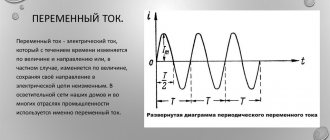
The total power of an alternating current circuit is the sum of active power and reactive power. Power factor is equal to the ratio of active power to apparent power, therefore, the lower the reactive power, the higher the power factor. In the general case, for non-sinusoidal currents and voltages, their functions must be expanded into a Fourier series and for each harmonic we will obtain its own power factor in the form of a trigonometric function of its phase angle, as well as its own current and voltage amplitudes. The sine function is most easily expanded into a Fourier series - this is the sine itself. Any transformation of energy according to the sine law is similar to uniform circular motion in mechanics with the center of mass on the axis of rotation. This is the most economical mode.
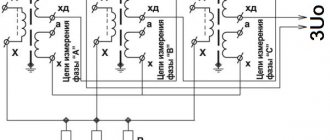
Power engineers at enterprises, and also household consumers, are mainly concerned about the first harmonic of the network voltage - 50 Hz, for which the power factor with high accuracy in practice is equal to cos φ. Power engineers of large energy companies are already interested in higher harmonics, because for their companies these are tangible rubles, which manifest themselves not so much in energy loss, but in interference with control, signaling and communication equipment. Usually people are interested in the 5th, 7th and 11th harmonics (these are prime numbers that complicate calculations). To suppress them, circuits with sequential resonance are used in powerful consumers.
Mathematically cos φ
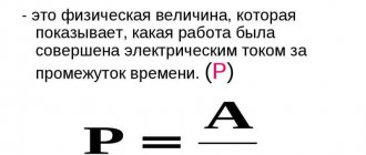
Mathematically, cos φ is defined as the ratio of active power to total power or equal to the ratio of the cosine of these quantities (hence the name of the parameter).
The power factor value can change in the range 0 - 1 (or in the range 0 - 100%). The closer its value is to 1, the better, since with a value of cos φ = 1, the consumer does not consume reactive power (equals 0), therefore, the total power consumed in general is less.
Low cos φ indicates that increased reactive power is released at the internal resistance of the consumer.
When the currents/voltages are ideal sine waveforms, then the power factor is 1.
Vasiliev Dmitry Petrovich
Professor of Electrical Engineering, St. Petersburg State Polytechnic University
In the energy sector, the following designations are used for power factor: cos φ or λ. If λ is used to determine the power factor, its value is expressed in %.
Geometrically, the power factor can be depicted as the cosine of the angle on a vector diagram between current and voltage between current and voltage. In this connection, with a sinusoidal shape of currents and voltages, the value of cos φ coincides with the cosine of the angle from which these phases lag.
A short video about a brief explanation of what power factor is:
Frequency converters
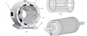
Today, an asynchronous motor is controlled using a frequency converter. The frequency converter has gone through a certain history of development. At first, thyristor circuits were used. These schemes had many disadvantages that hampered the development of converters, although they were quite actively used, especially for powerful engines. When MOSFETs and then IGBT transistors appeared, the converter market, as they say, “exploded.” The average cost of a frequency converter has begun to fall, and today a frequency converter can be purchased even for domestic purposes for several thousand rubles.
By the time the IGBT was introduced, many power topologies and control methods for frequency converters had been proposed and tested. Converters are divided into direct and two-stage DC frequency converters. Direct - directly transfer energy to the engine: for example, cycloconverter, matrix converter. The big disadvantage of these converters is the significant number of keys and the great complexity of managing them. They were used mainly in the thyristor era.
The two-tier frequency converter circuit contains a three-phase inverter, powered by a direct current or voltage source. Consequently, it requires a rectifier, which is another link. These converters are more promising, since they allow regeneration on alternating current, and this, perhaps, would be the final solution to the problem of the electric drive. The following figure explains this important issue:
The figure shows a current inverter. It powers the motor and the capacitors in its circuit. DC link chokes limit noise. Capacitors smooth out PWM current ripples. The current inverter requires a controlled rectifier link to regulate the voltage and control the current in the intermediate link. The output inverter uses IGCT (Integrated Gate-Commutated Thyristor) turn-off thyristors. This is a fairly new type of device; the industry does not yet have much experience in their use, but developers are interested in their capabilities. IGCT is quite a complex thing:
since it contains the driver directly next to the device. The figure shows the clamping option. You can see a lot of capacitors on the board - this is required to increase the speed of the control electrode. The switching frequency is on the order of a few kHz. This is already suitable for a frequency converter. The current inverter may not extinguish the energy in the braking resistors, but return it to the power supply network.
But the most commonly used are voltage inverters. Their rectifying section is made of diodes, and the inverter is made of IGBT transistors, shunted by diodes connected in the reverse direction. The DC link contains capacitors and a choke to smooth out ripples. The voltage inverter has quite a few options. The fact is that in order to effectively regulate powerful motors in the DC link of the frequency converter, it is necessary to use high voltage, and for this it is necessary to use multi-level inverter circuits in order to divide the voltage between the devices and avoid their breakdown. There are schemes: three-level, with a fixed midpoint; cascade with more than three levels; circuits with floating capacitors. Most sold converters are produced according to a simple design for three-phase motors of low and medium power operating in 50-60 Hz 0.4 kV networks.
The frequency converter circuit fits in a small box, the size of a shoe box, for low-power frequency converters, while powerful high-voltage converters for large motors can occupy several metal cabinets.
Power factor improvement
The power factor value is calculated when designing networks. Since its low value is a consequence of an increase in the amount of total electricity losses. To increase it, networks use various correction methods, increasing its value to 1.
Increasing cos φ has 3 main objectives:
- reduction of electricity losses;
- rational use of non-ferrous metals to create electrically conductive equipment;
- optimal use of the installed power of transformers, generators and other alternating current machines.
Technically, correction is implemented in the form of introducing various additional circuits to the device input. This technique is required for uniform use of phase power, eliminating overloads of the neutral wire of a 3-phase network, and is mandatory for switching power supplies with an installed power of 100 W or more.
Abrahamyan Evgeniy Pavlovich
Associate Professor, Department of Electrical Engineering, St. Petersburg State Polytechnic University
In addition, compensation makes it possible to ensure that there are no surges in the consumed current at the peak of the sinusoid, and that the load on the supply line is uniform.
AC drive
Controlled AC drives using an asynchronous electric motor are of particular importance in technology. If an engineer from the thirties of the last century had seen what they were now doing with the help of these simple, cheap and “unfortunately uncontrollable” engines, he would have burst with envy. The only way to effectively change the rotation speed of such a motor is to change the frequency of the voltage on it. In the thirties of the last century, it was possible to change the frequency only at a power plant, looking at a reed frequency meter, within a few Hz. All that had to be done then was to keep it at par, in the middle of the scale. Everything else was still in theory.
Basic methods of cos φ correction
1. Correction of the reactive component of power is carried out by turning on a reactive element that has the opposite effect. For example, to compensate for the operation of an asynchronous machine with a high inductive reactive component of power, a capacitor is connected in parallel.
2. Correction of nonlinearity of power consumption . When the load's current consumption is disproportionate to the fundamental harmonic of the voltage, a passive (active) power factor corrector is introduced into the circuit to increase the power factor. The simplest example of a passive cos φ corrector is a high-inductance inductor connected in series with the load. The inductor smoothes out pulsed load consumption and creates the lowest, fundamental current harmonic.
3. Correction in a natural way , which does not involve the installation of additional devices, involves streamlining the technological process, rational distribution of loads, leading to an improvement in the electricity consumption of equipment and an increase in the power factor.
Detailed video explaining what cosφ is:
CONTENTS AND DESIGN OF THE WORK REPORT
The report is completed by each student on a separate sheet. The report must contain the title of the laboratory work, a statement of the purpose of the work, a list of instruments used and their characteristics, the results of observations and calculations; formulas used in calculations, graphs and vector diagrams made on graph paper (or on checkered paper).
The report must contain information on assessing the accuracy of measured and calculated values.
The report ends with conclusions on the work, in which it is necessary to reflect: what values of capacitance and reactive power of capacitors are needed to compensate for the reactive inductive current in the line; is the current resonance condition fulfilled (P=S; Ia=min); how many times does the current in the line decrease after connecting the capacitors and how many times do the voltage and power losses in the line decrease?
Indicate the main sources of measurement and calculation errors.
SELF-TEST QUESTIONS
1. What role do reactive currents play in the load and in the power line wires?
2. For what purpose is a capacitor connected in parallel with inductive receivers of electrical energy?
3. How to calculate the capacitance and power of the compensating capacitor?
4. How does the active power of the load change if a capacitor is connected to it?
5. Does the operating mode of an inductive electrical energy receiver change when a capacitor is connected in parallel to it (Ιheat, Ρload, Qload)?
6. How do voltage and power losses in the line wires change if a capacitor is connected in parallel with an inductive load?
7. Indicate on the laboratory diagram the path of flow of active current, reactive inductive and reactive capacitive current.
8. Write the formula for Ohm’s laws for an alternating current circuit with series and parallel connections of branches.
9. In what circuits does current resonance occur? Give a definition of current resonance modes. Condition for the occurrence of current resonance.
10. What are the properties of the circuit in the current resonance mode.
11. Explain the procedure for constructing a vector diagram when connecting branches in parallel.
Task 2
educational and research
Study of a single-phase sinusoidal current circuit with a parallel connection of an inductive coil and a variable capacitor
Goal of the work
: to study the influence of the capacitance value on the change in the magnitude and phase of the current in the line and on the magnitude and nature of the reactive power consumed by a circuit consisting of an inductive coil and a variable capacitor connected in parallel.
EQUIPMENT AND ACCESSORIES
When performing this task, the same equipment and supplies are used as in learning task 1, without any additions.
EXPERIMENTAL PROCEDURE
1. Assemble a circuit diagram and show it to the teacher for verification;
2. Prepare table 3 of measurements and calculations, which should have at least 7 lines for recording the results of observations.
Table 3.
| № p.p. |