In various situations, it may be necessary to convert the frequency of the original current into a current with a voltage of controlled frequency. This is required, for example, when operating asynchronous motors to change their rotation speed. This article will discuss the purpose and operating principle of a frequency converter.
Advantages of using frequency converters
Frequency converters are widely used in a wide variety of production niches and equipment. Such a high demand for such devices is due to the following advantages of their use:
- Reduce starting current. When starting an electric motor using direct starters, a sharp increase in current is observed, the value of which exceeds the rated value by 7-15 times. This has a negative impact on the electric drive and can lead to insulation breakdown, contact burnout and a number of other negative consequences. In addition, this starting method also affects the mechanical components of the system. At the moment of start-up, the working components of the engine are subjected to high loads, which leads to their faster wear. Thanks to frequency converters, it is possible to significantly reduce the starting load on the electric motor, extending its maintenance-free operation.
- Economical. As a rule, the motors that support the operation of ventilation and pumping systems always operate at the same frequency, and pressure and other operating parameters are regulated using fittings (vanes, dampers, etc.). This leads to wasted energy consumption. In the case of using frequency converters, it is possible to adjust the operating parameters of the system by adjusting the intensity of the engine. This makes it possible to use its resources more rationally.
- Increased adaptability. When using frequency converters, it is possible to design automated systems that, according to established algorithms, will correct the operation of the equipment. This reduces the labor costs of production processes and makes them more accurate by eliminating the human factor.
- Maintainability. If the frequency converter breaks down, you can take it to a workshop, where a technician will replace the failed parts. True, this only applies to the electrical converting unit - with control units everything is much more complicated and they are more demanding in terms of restoration.
Frequency converters are the optimal solution for organizing a wide variety of production processes and debugging working equipment based on which electric motors are used.
Model Reviews
Let us highlight the following models of the equipment in question:
Omron MX2
The cost of this model is 15,000 rubles. The power value is 0.75 kW, the output current is 2.1 A. The weight of such a unit is 1.5 kg. The unit is compact and easy to use. This version has a built-in control unit.
Vacon NXL
The cost is about 24,000 rubles. Power value 1.1 kW, output current 3.3. The weight of the block is 5 kg. Quite an expensive model, despite a slight increase in output figures.
Intermediate chain
The intermediate circuit acts as a kind of storage facility from which the electric motor receives energy through the inverter. Depending on the combination of inverter and rectifier, the intermediate circuit can have one of the following formations:
- Inverter power supply. In this case, the intermediate circuit contains a powerful inductive coil, which converts the rectifier voltage into a varying direct current. The motor voltage itself is determined by the load. This type of circuit can only work with controlled rectifiers.
- Inverters are voltage sources. In this case, a filter is used in the intermediate circuit, which includes a capacitor. It smoothes out the voltage coming from the rectifier. Such circuits can work with any type of rectifier.
- Circuit of varying direct voltage. In this case, a breaker is installed in front of the filter, which contains transistors that switches off and on the voltage supply from the rectifier. In this case, the filter smooths out the rectangular voltages after the chopper, and also maintains a constant voltage at a given frequency.
Inverter
The inverter is the last link in the frequency converter before the electric motor itself. It is he who finally converts the voltage into the form required for work. Due to the above-described transformations occurring on the rectifier and intermediate circuit, the inverter receives:
- Direct current of varying nature.
- Varying or constant DC voltage.
Actually, the inverter itself provides the supply of voltage at the required frequency. If a variable voltage or current is supplied to it, then it creates only the desired frequency. If it is unchangeable, then it creates both the desired frequency and the required voltage.
Typically, inverter designs use high-frequency transistors, the switching frequency of which is in the range from 300 to 20 kHz.
Design. Types of converters
A frequency electric drive has a number of circuits that include a transistor or thyristor. The basic element of the electronic circuit is a microprocessor, which is responsible for the operation of additional circuit elements and ensures the performance of a large number of additional tasks.
A frequency converter is a group of rectifiers, as well as inverters that transform alternating currents into direct currents.
Single-phase frequency converter is a high-tech device. Its main task is to convert the operating voltage of the network into household voltage (220 V). With this transformation, a voltage pulse is performed at the required frequencies (1 – 1000) Hz.
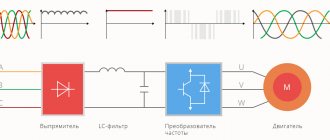
The frequency converter for the electric motor creates voltages with the specified parameters. The frequency converter works as follows:
- First, the voltage of the electrical network is rectified, as well as pulse reduction and harmonic filtering.
- DC voltage is supplied from the rectifier to the inverter circuit, where it is transformed into alternating voltage with varying amplitude and frequency.
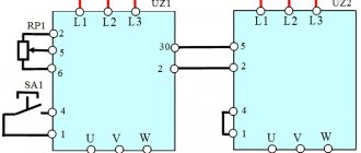
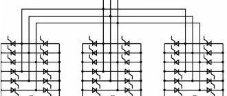
Fig. 1 Schematic diagram of a frequency converter
The role of power elements is often performed by IGVT transistors. By changing the frequency, you can change the rotation speed of the electric motor (M).
The frequency converter is divided into two large types:
With direct communication.
Their distinctive feature is a thyristor rectifier, where individual thyristors alternately open and close and are alternately connected to the stator coil.
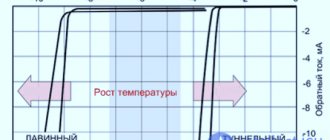
Rice. 2 Graphical representation of the converter voltage
The output voltage of the sinusoid forms a sawtooth shape with a frequency of about 1 – 40 Hz. The scope of application of this kind of converters is considered limited due to the fact that non-lockable thyristors require more complex control circuits. Which brings with it a higher cost of equipment.
Such frequency converters operating with high currents and voltages have an efficiency of about 95-98%. Also, high-voltage frequency converters have a higher cost compared to low-voltage ones.
If we compare a thyristor converter with a transistor electric drive that has similar power, then the second device will have significantly smaller dimensions, lighter weight and will be more reliable.
With a pronounced DC link.
This type of sensor is much more common in modern devices whose purpose is to regulate frequency.
The transformation occurs in 2 stages:
- first, the mains voltage is rectified and filtered;
- then the signal is supplied directly to the inverter, where the current of the required frequencies and amplitudes is transformed into alternating current.
The efficiency of such a transformation decreases, while the dimensions of the device increase. The sinusoidal signal is provided by an independent voltage and current inverter.
Vector control of frequency converter
The principle of operation of vector control is as follows: it affects the magnetic flux, changing the direction of its “spatial vector” and regulating the rotor frequency of the field.
You can create a working algorithm for a frequency converter with vector control using two methods:
Touchless control.
It is carried out by assigning alternation dependencies between sequences of pulse-width modulations of the inverter for pre-compiled algorithms. The regulation of the amplitude size and output frequency that the voltage has is carried out according to the slip and load current, but the feedback from the rotor rotational speed is not taken into account.
Flow regulation.
The operating currents of the device are adjustable. At the same time, they are decomposed into an active and reactive component. This makes it easier to make corrective changes to the workflow (changes in amplitudes, frequencies, vector angles of the output voltage).
In general, the vector control circuit is more suitable than others for dynamically adjusting the rotating torque of a three-phase asynchronous motor.
Classification and types
All frequency converters for electric motors can be divided into several groups:
- Individual. Designed for a specific type and characteristics of the motor.
- Universal. Thanks to the ability to change parameters, they can work with different engines.
- Specialized. Developed for specific types of equipment. For example, converters for pumping stations (pumps) and fans (Mitsubishi FR-F740).
- Intelligent. They have a built-in personal computer and have self-diagnosis functions. The inverter itself monitors the condition of wear parts and reports the need for replacement when the service life comes to an end.
The cheapest ones are individual ones. But they can only work exclusively with motors of the same type/power. Specialized ones also have a rather limited range of connected equipment. Universal ones, from this point of view, are good, but they cost much more (more complex circuit and more components).
You need to choose for a specific device
But, still, the most expensive ones are intellectual ones. Many of them can be controlled using a touch panel rather than a set of controls. In addition, most models have a remote control. This is convenient, since the frequency controller can be installed far away. Usually they are placed in cabinets or somewhere at the entrance. If you have a remote control, you can regulate the operation while being near the engine and without running to the cabinet.
Frequency converter device
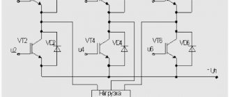
In most cases, the frequency converter device is based on a double conversion circuit. The units include: a DC link (uncontrolled rectifier), a power pulse inverter and a control system. In turn, the DC link includes an uncontrolled rectifier and a filter. Here the alternating voltage of the network is converted into direct current voltage. The power three-phase pulse inverter includes six transistor switches and each motor winding is connected through a specific switch to the positive/negative terminals of the rectifier. By means of an inverter, the rectified voltage is converted into a three-phase variable value of the required frequency and amplitude, applied to the stator windings of an electric motor.
Power IGBT transistors are used as switches. If we compare them with thyristors, the former have a higher switching frequency, which makes it possible to produce a sinusoidal output signal with minimal distortion. Information on how to connect and configure the frequency converter will be discussed below. This section only shows the general structure of the frequency converter for reference.
Rectifier
This component is designed to generate pulsating voltage in single- or three-phase AC networks. Rectifiers are usually built using either diodes or thyristors. In the first case, they are considered uncontrollable, and in the second, manageable.
- Uncontrolled rectifiers. Their design uses two groups of diodes, which are connected to different terminals and conduct different voltages - positive and negative. Ultimately, the output voltage is equal to the voltage difference across these groups of diodes and in mathematical expression has the following value: 1.35 * input network voltage.
- Controlled rectifiers. In the design of such rectifiers, thyristors are used instead of diodes. They can receive an input signal a, which stimulates a current delay expressed in degrees. In cases where the value of this parameter fluctuates between 0-90 degrees, thyristors play the role of rectifiers, and when 90-300 degrees - an inverter. The output constant voltage value is: 1.35* input network voltage*cos α.
Caring for the Transducer
To extend the service life of the inverter, you should take proper care of it:
- Monitor the accumulation of dust on the internal elements and promptly clean the device using a compressor.
- Make sure that the components used in the mechanism are working properly and replace them if the need arises.
- Maintain adequate operating temperature (no more than +40°C) of the mechanism and voltage level on the control bus.
- Regularly (at least once every 3 years) update the layer of thermal paste on the power components of the device.
- Maintain moderate humidity levels if possible.
How to choose a frequency converter?
There are several main parameters that you need to pay attention to when choosing a frequency converter:
Power. This parameter of the frequency converter must correspond to the power of the engine with which it will be used. You should choose a device whose power will correspond to the rated current. It is simply pointless to buy a frequency converter with very high characteristics, because it will cost much more, and problems may arise with setup. Load type. It all depends on how the unit to which the frequency converter will be connected operates. For example, with fan loads there are no overloads, but in the case of press operation, the current can exceed the rated values by 60 percent or more. Accordingly, it is necessary to take this into account when choosing and leave a certain “move” reserve. Engine cooling type. Engines can be equipped with forced cooling systems or have self-blowing. In the second case, special blades are attached to the rotor impeller, which rotate with it and blow over the engine. Accordingly, the normal degree of airflow in this case directly depends on the rotation speed. If the engine runs for a long time at a reduced frequency, this may lead to overheating. Accordingly, it is better to take care of additional cooling if the frequency change is more than 10% of the nominal value. Input voltage. This indicator determines at what voltage the frequency converter is capable of operating. It’s not enough to know that the network voltage is usually about 380 V. Jumps often occur in the range of +-30%. In addition, in networks where a large number of power equipment are connected, surges of 1 kV often occur. Accordingly, the wider the operating voltage range of the frequency converter, the more reliable it will work. Braking method. Stopping the engine can be done either by an inverter bridge or by an electrodynamic method. The first method is more suitable for precise and fast braking, and the second - in mechanisms with frequent braking or when a gradual stop is necessary
You should definitely pay attention to this. Environment and protection. Typically, the passport of the frequency converter indicates the conditions under which the device should be used
For example, waterproof models comply with the IP 54 standard - they are resistant to moisture and can be used in rooms with steam fumes and high humidity. Control type and interfaces. It is imperative to pay attention to the availability of suitable connectors, as well as control capabilities - some models are designed for on-site installation, while others are designed for a separate control room.
If you have never worked with frequency converters, it is better to seek advice from a specialist.
Connecting a three-phase motor via a manual starter
4. Connecting the motor via a manual starter. PRACTICAL SCHEME
Since motors usually have a high starting current, motor circuit breakers (automatic motors) usually have a thermal protection characteristic of type D. That is it can withstand short-term (starting) overloads of approximately 10 times the nominal value.
Manual motor starter with additional control contact.
Here's what's on the side:
Motor circuit breaker - characteristics on the side wall
Setting current (thermal) – from 17 to 23 A, set manually. Cut-off current (trigger during short circuit) – 297 A.
In principle, a manual starter and an automatic motor are the same device. But the starter shown in the photo can switch the power supply to the engine. And the automatic motor constantly supplies power (three phases) to the contactor, which, in turn, switches the power to the motor. In short, the difference is in the connection diagram.
The advantage of the scheme is that you can adjust the thermal current setting. The disadvantage is the same as in the previous scheme - there is no remote activation.
How is the frequency converter connected?
If we consider the installation of a frequency converter schematically, then the whole process comes down to connecting the contacts of the device itself, the electric motor and the control fuse block. It is enough to connect the wires of all elements, connect the engine to the network and start it.
At first glance, there is nothing complicated about this, but, in fact, the installation procedure has some of its own nuances:
It is very important that a fuse is installed in the circuit between the frequency converter itself and the power source. It will allow you to promptly turn off devices in case of voltage surges, maintaining their functionality
It is noteworthy that when connecting to a three-phase network, it is necessary that the fuse itself is also three-phase, but has a common disconnect lever. This will make it possible to turn off the power on all phases at once, even if only one has a short circuit or overload. If the converter is connected to a single-phase network, then the fuse must be single-phase. In this case, when making calculations, it is necessary to take into account the current of only one phase, but multiplied by 3. It is always worth remembering that the instructions for almost any converter indicate the requirements and standards for its installation. You need to familiarize yourself with them before starting work. The phase outputs of the frequency converter are connected to the contacts of the electric motor itself. In this case, depending on the voltage of the frequency converter, the motor windings may have a “star” or “triangle” formation. There are usually two voltage values marked on the motor housing. If the frequency driver corresponds to the smaller one, then the windings are connected in a “star”, if the larger one corresponds to a “triangle”. All this information is usually printed in the instructions. Almost every frequency converter comes with a remote control panel. It is not a mandatory element of the circuit, because the device itself also has its own controls, but it can significantly simplify the work with the equipment. The remote control can be mounted at any distance from the frequency generator. This is usually done as follows: frequency converters that have a low degree of protection are located away from the engine, and the remote control itself is taken directly to the workplace near the equipment.
An equally important stage in installing a frequency converter is its test run. It works according to the following scheme:
- After connecting all elements of the system (fuse, control panel, frequency converter, motor), it is necessary to move the handle on the control panel to the active position by several degrees.
- Switch the fuse switches to the “ON” position. After this, the indicator lights on the frequency converters should light up, indicating that the equipment is connected correctly, and the motor should begin to rotate slowly.
- If the motor shaft begins to rotate in the opposite direction, it is necessary to reprogram the frequency converter itself for reverse movement. Almost all modern devices support this function.
- Move the control handle gradually and monitor the engine operation - the shaft speed should increase as you move the handle.
If no problems were found during the test run, then you have done everything correctly and the system can be included in the workflow.
Self-assembly
Despite the fact that purchasing a reliable and durable frequency converter is a priority option, such a device can be assembled with your own hands. There are more than one diagram and instructions on how to do this on the World Wide Web. In fact, DIY can be a great alternative when you need a converter for a small home appliance. A homemade device will cope with its tasks no worse than a purchased one, and will cost much less. But it is better to abandon attempts to create a suitable converter for operating powerful asynchronous motors - here, no matter how hard you try, you will not be able to surpass professional devices in efficiency and quality.
So, let's take a closer look at how to assemble a frequency converter for an asynchronous motor with your own hands. Please note that the parameters of a single-phase home electrical network allow the use in this case of a motor with a power of no more than 1 kW.
- For the engine to operate, we need a triangle connection diagram for the windings. To do this, you need to connect the terminals of the windings to each other in series, observing the principle of “the output of one winding to the input of another.”
- In order to construct a converter with our own hands, we need the following components:
- any microcontroller similar to AT90PWM3B;
- three-phase bridge driver (analogue IR2135);
- 6 transistors IRG4BC30W;
- 6 buttons;
- indicator.
- The design of the device we are creating includes two boards, one of which contains the driver, power supply, input terminals and transistors, and the second - an indicator and a microcontroller. To connect the boards to each other we will use a flexible cable.
- To assemble the frequency converter, you must use a switching power supply. You can use a ready-made device, or assemble it yourself (we will not describe this process - this is a topic for a separate article).
- To control the operation of the motor, it is necessary to supply an external control current, but we can use the IL300 microcircuit with linear decoupling. Image
- Transistors and a diode bridge are installed on a common radiator.
- Optocouplers OS2-4 are used to duplicate control buttons.
- Installing a transformer on a single-phase frequency converter for a small-power motor is not a necessary step. You can get by with a current shunt with a wire cross-section of 0.5 mm, and connect the DA-1 amplifier to it (by the way, it will also be used to measure voltage).
- In our case, we are assembling a converter for an asynchronous motor with a power of 400 W with our own hands, so we will not install a temperature sensor - the circuit is quite complicated without it.
- Upon completion of assembly, it is necessary to isolate the buttons using plastic pushers. The buttons are controlled using an optical coupler.
Please note that when using long wires, they must be fitted with noise suppression rings.
It allows you to adjust the motor rotation in a frequency range of 1:40.
Operating principle of the frequency converter
The operating principle of the frequency converter is based on the operating features of an asynchronous electric motor. In an electric motor of this type, the rotation frequency of the magnetic field (n1 value) depends on the frequency of the supply voltage. In the case when the stator winding is powered by a three-phase voltage having a frequency f, a rotating magnetic field is generated, the rotation speed of which is determined by the formula below:
, Where
p is the number of pairs of stator poles.
The transition from the field rotation speed ω1, which is measured in radians, to the rotation frequency n1 (rpm), is performed according to the formula:
, Where
60 is the dimension conversion factor.
If we substitute the field rotation speed ω1 into this equation, we obtain the following equality:
From this it is easy to conclude that the rotor speed of an asynchronous electric motor depends on the frequency of the supply network voltage. It is this dependence that reflects the whole essence of the frequency regulation method. The frequency converter for the electric motor changes the frequency of the supply voltage at the input and, as a result, regulates the rotor speed. We emphasize that the output frequency in modern frequency converters varies over a wide range, which means that this value can be either lower or higher than the frequency of the supply network.
The frequency converter for the electric motor, the principle of operation of the power unit of which formed the basis for the classification below, corresponds to the following parameters:
- Converters with a clearly defined intermediate DC link.
- Converters with direct coupling (no intermediate DC link).
By historical standards, direct-coupled frequency converters were the first to appear. In these units, the power part is a controlled rectifier made using thyristors. The control node, in turn, unlocks groups of thyristors, thereby generating an output signal. Today this conversion method is not used in new developments.
How does this class of converter work? Here, double conversion of electricity is used: the input sinusoidal voltage (values L1, L2, L3 in the figure) with a constant amplitude/frequency is rectified in the rectifier unit (BR), filtered and smoothed in the filtering unit (BF), as a result, we obtain a constant voltage. The presented unit is called the DC link.
The conversion unit (BD) is responsible for solving the problems of generating a sinusoidal alternating voltage with an adjustable frequency. The role of electronic switches that generate the output signal is performed by bipolar transistors with an insulated gate IGBT. The process of controlling the above blocks occurs according to a pre-programmed algorithm by a microprocessor module or logical block (BL).
The diagram below shows that frequency converters can be powered from an external DC link. In this case, the protection of the frequency generator is carried out using high-speed fuses
It is important to note that the use of contactors for DC link power is not recommended. The fact is that during contactor switching, an increased charging current occurs and the fuses can burn out
Frequency converter device
In most cases, the frequency converter device is based on a double conversion circuit. The units include: a DC link (uncontrolled rectifier), a power pulse inverter and a control system. In turn, the DC link includes an uncontrolled rectifier and a filter. Here the alternating voltage of the network is converted into direct current voltage. The power three-phase pulse inverter includes six transistor switches and each motor winding is connected through a specific switch to the positive/negative terminals of the rectifier. By means of an inverter, the rectified voltage is converted into a three-phase variable value of the required frequency and amplitude, applied to the stator windings of an electric motor.
Power IGBT transistors are used as switches. If we compare them with thyristors, the former have a higher switching frequency, which makes it possible to produce a sinusoidal output signal with minimal distortion. Information on how to connect and configure the frequency converter will be discussed below. This section only shows the general structure of the frequency converter for reference.
Timing diagrams of the Star-Delta circuit operation
With reference to my control circuit, contactor switching diagrams:
Star-delta control timing diagrams
Everything seems clear here, but there is one important note. Again
A small gap (pause) is required between the green and red areas. It may not exist (pause = 0), but these areas can overlap each other if contactors with a DC coil (=24 VDC) are used. Especially when using a reverse-connected diode (and it is required!), the turn-off time can be 7-10 times longer than the turn-on time!
What I mean is that I once suffered with such a scheme; it periodically knocked out the input machine. We installed a special relay with a pause, the problem was solved!
How to choose an inverter before buying it
Before choosing a frequency converter, check the electrical compatibility with the motor and load capacity (power).
Rice. No. 1. Block diagram of the operation of a system of pumping units from a VFD frequency converter.
When operating a frequency converter with one motor, the choice is made depending on the rating characteristics. When choosing, the following indicators are taken into account:
- According to the passport, the power of the inverter and the electric motor must be equal. This parameter is valid when using motors with two pairs of poles (2p=4), with rotation speeds up to 1500 rpm, with constant torque. It also applies to inverters that can cope with an overload of 150% (conveyors, conveyor belts) and for converters operating with an overload of 120% (fans, centrifugal pumps).
- The rated current must be equal to or greater than the continuous actual current consumed by the motor (load current).
The motor acceleration time at a starting current of 150% is 120% for converters specializing in pumping units, from the rated inverter usually should not exceed 60 seconds.
- The input voltage of the network must satisfy the converter; it must maintain its functionality even with any voltage deviations from the norm.
- The frequency regulation range that the inverter can support must satisfy the high-speed mode of the motor.
- The presence of discrete control inputs is necessary for entering various types of commands programmed by the user. Analog ones are also needed; they are used to input task signals and for feedback. Digital inputs are also required for high-frequency signals coming from encorders or digital speed and position sensors.
- A number of output signals are used to create complex circuits for a pumping station system.
- Possibility of operational control in operating mode, these can be control inputs using a remote control. Or control via a serial communication bus via a controller or computer. Maybe it will be combined control.
- The choice of converter depends on the preference for the motor control method, scalar or vector control. Depends on separate vector motor control or scalar control - maintaining one constant ratio of output voltage to output frequency. For pumping units, the vector control method is more typical.
- More precise criteria for choosing a frequency driver include the parameter that determines the operation of the engine at steady speed. When the converter operates with one motor, the required power for starting is calculated by the formula:
Rice. No. 2. Formula for calculating total starting power.
The motor current consumption from the converter at a mains voltage of 220/380V is calculated using the formula:
Rice. No. 3. Calculation of mechanical characteristics of the engine.
Rice. No. 4. A table of inequalities that must be observed when choosing an inverter for operating one frequency drive with several motors.
Diagram of connecting a three-phase motor to the network via a circuit breaker
Therefore, in more detail, the general case will look like this:
3. Connecting the motor via a circuit breaker. PRACTICAL SCHEME
Diagram 3 shows a circuit breaker that protects the motor from overcurrent (“rectangular” bends in the supply lines) and from short circuits (“round” bends). By circuit breaker I mean a regular three-pole circuit breaker with a load thermal characteristic of C or D.
Circuit breaker for turning on the electric motor. The current is 10A, through which you can turn on a 4 kW motor. No more and no less.
Scheme 3 has the right to life (due to poverty or ignorance of local electricians).
If you use such a circuit, you need to carefully select the current of the machine so that it is 10-20% greater than the operating current of the motor. And select the characteristic of the thermal release D, so that during a difficult start the machine does not trip.
For example, a 1.5 kW engine. We estimate the maximum operating current - 3A (real operating current may be less, we need to measure it). This means that the three-pole circuit breaker must be set to 3 or 4A, depending on the starting current.
The advantage of this motor connection diagram is the price and ease of execution and maintenance. For example, where there is one engine, and it is turned on manually for the entire shift. The disadvantages of such a scheme with switching on via an automatic machine are:
- Inability to regulate the thermal current of the machine. In order to reliably protect the engine, the shutdown current of the circuit breaker must be 10-20% greater than the rated operating current of the engine. The motor current must be periodically measured with clamps and, if necessary, the thermal protection current must be adjusted. But a regular machine does not have the ability to adjust (.
- Inability to remotely and automatically turn on/off the engine.
These shortcomings can be eliminated; the diagrams below will show how.