Designation of resistors in the diagram.
Let's look at the designation of resistors in the diagrams. There are two possible options:
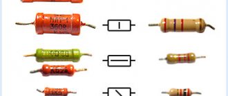
In addition, slightly modified symbols are used that characterize the resistors in the diagram according to their rated power dissipation . A completely logical question arises here - what kind of parameter is this - the rated dissipation power? When current flows through a resistor, power will be released in it, which will cause the resistor to heat up. And if the power exceeds the permissible value, the resistor will overheat and simply burn out. Thus, the rated power dissipation is the amount of power that can be dissipated by a resistor without exceeding the maximum permissible temperature. That is, if the power in the circuit is less than or equal to the rated value, then everything will be fine with the resistor. Let's return to the designation of resistors:
This is how the resistors most often found in circuits are designated depending on their rated power dissipation. There is not even much to comment further on here.
The resistance of the resistor in the diagrams is indicated next to the symbol, and the unit of measurement is usually omitted. If you see the number 68 next to the resistor on the diagram, then have no doubt - the resistance of the resistor is 68 ohms. If the resistance value is, for example, 1500 Ohm (1.5 KOhm), then the diagram will indicate “1.5 K”:
This one is simple. The situation is somewhat more complicated with the color marking of resistors. Now let's deal with this too.
Definitions and calculation
Resistor and resistance
A resistor
is a passive electrical element that creates
electrical resistance
in electronic circuits. Resistors can be found in almost all electronic devices. They are used for various purposes, in particular, to limit current in circuits, as voltage dividers, to provide bias voltage for active elements of electrical circuits, as terminators (matched loads) of transmission lines, in RC circuits as a timing element... The list goes on and on.
Decade resistance store
The electrical resistance of a resistor or any conductor is a measure of its resistance to the flow of electric current. In SI, resistance is measured in ohms. Almost any material has resistance except superconductors, which have zero resistance. Learn more about resistance, resistivity and conductivity.
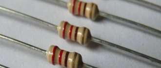
Color coding of resistors.
Most terminal resistors are color coded, such as in this picture. It consists of 4 or 5 stripes (most often, although there can be, for example, 6) of certain colors, and each of these stripes carries a certain meaning. The first two stripes absolutely always indicate the first two digits of the nominal resistance of the resistor. If there are 3 or 4 stripes in total, then the third stripe will indicate the multiplier by which you need to multiply the number obtained from the first two stripes. When there are 4 bands on a resistor, the fourth will indicate the accuracy of the resistor.
And in the case when there are only five bands, the situation changes somewhat - the first three bands mean three digits of the resistor resistance, the fourth is the multiplier, the fifth is the accuracy. The correspondence of parameters to colors is given in the table:
There is another important point here: which lane should be considered first. Most often, the first strip is considered to be the one that is located closer to the edge of the resistor. In addition, you can notice that the gold and silver stripes cannot be first, since they do not carry information about the value of resistance. Therefore, if the resistor has stripes of this color and they are located on the edge, then we can say for sure that the first stripe is on the opposite side. Let's look at a practical example:
Since we have 5 bands here, the first three indicate the resistance of the resistor. Having looked at the required values in the table, we get the value 510. The fourth band is the multiplier - in this case it is equal to 103. And, finally, the fifth band is the error - 10%. As a result, we get a resistor of 510 KOhm, 10%.
In principle, if you don’t want to deal with colors and values, then you can turn to some automated service that determines resistance by color markings. You will only need to select the colors that are applied to the resistor, and the service will display the resistance value and accuracy.
So, we’ve sorted out the color coding of resistors, let’s move on to the next question.
Briefly about the characteristics displayed in the markings
All types of resistors display the value and tolerance. Denomination is the main characteristic, but it’s impossible without approval. The tolerance is indicated as a percentage. It shows the magnitude of the possible deviation of the real value from the declared nominal value.
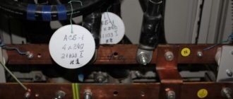
Sometimes the series or type is indicated
Even on old resistors, the series or type of resistor may be indicated. But this is on “Soviet” ones with alphanumeric markings. This is not available in the color version.
Code marking of resistors.
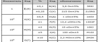
In addition to color marking, the so-called code marking is used. In this case, letters and numbers (four or five characters) are used to indicate the resistor value. The first characters (all but the last) are used to indicate the resistor value and include two or three numbers and a letter. The letter determines the position of the decimal point, as well as the multiplier. The last character determines the permissible deviation of the resistor resistance. The following values are possible:
For letters denoting a multiplier, the following options are possible:
Let's look at a few examples for clarity:
We’ve also sorted out this type of marking, now let’s study all sorts of ways to mark SMD resistors.
Types of resistors according to the nature of the current-voltage characteristic
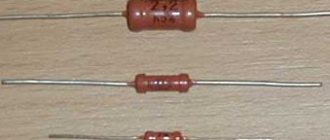
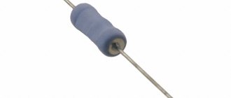
According to the current-voltage characteristics, resistors are divided into linear and nonlinear. The resistance of linear elements does not depend on voltage and current, but the resistance of nonlinear elements varies depending on these (or other) quantities. Small-sized linear parts of the MLT type (metalized varnished heat-resistant) are used in communication equipment - tape recorders and radio receivers.
An example of nonlinear resistors is an ordinary light bulb, whose resistance in the off state is much lower than in the lighting mode. In photoresistors, the resistance changes under the influence of light, in thermistors - temperature, strain gauges - deformation of the resistor layer, magnetoresistors - magnetic field.
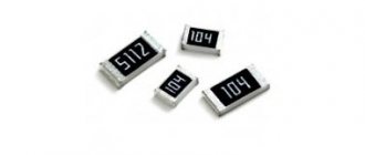
Marking of SMD resistors.
For SMD resistors there are also different options for designating values. So, let's figure it out:
- Marking with three numbers. In this case, the first two digits are the resistance value in Ohms, and the third digit is the multiplier. That is, the value in Ohms must be multiplied by ten to the degree corresponding to the multiplier.
- Marking with four numbers. Here everything is similar to the previous version, only the first three digits are used to indicate the resistance value in Ohms, not two. The fourth digit is the multiplier.
- Resistors are marked with two numbers and a symbol. In this case, two numbers determine the resistance of the resistor, but not directly, but through a special code. Below I will provide a table of all possible codes. If the code “02” is indicated on the resistor, then from the table we get the value of 102 Ohms. But this is not the final value of the resistance) We also need to take into account the third symbol, which is a multiplier. The following options are possible for this symbol: S=10-2; R=10-1; B=10; C=102; D=103; E=104;
Table of codes corresponding to resistance values:
In the first two marking options, it is also possible to use the Latin letter “R” - it is placed to indicate the position of the decimal point. As usual, let's look at a couple of examples:
Why is a resistor needed in an electrical circuit?
A clear example of how a resistor works
Using a resistor in an electrical circuit, the current is limited, obtaining its desired value. According to Ohm's law, the greater the resistance at a stable voltage, the less the current.
Ohm's law is expressed by the formula U = I*R, in which:
- U – voltage, V;
- I – current strength, A;
- R – resistance, Ohm.
Also resistors work as:
- current to voltage converters and vice versa;
- voltage dividers, this property is used in measuring devices;
- elements to reduce or completely remove radio interference.
Resistor values.
Resistor values are not arbitrary numbers. There are special series of values , which represent values from 0 to 10. So, resistor values (resistance values) can have values that are defined as the value from the corresponding series multiplied by 10 to the integer power. Let's look at the main rows - E3, E6, E12 and E24:
The number in the name of the series means the number of numbers in the series of denominations in the range from 0 to 10. In series E3 there are three numbers - 1.0, 2.2, 4.7, similarly in other series. Thus, if the resistor is from the E3 series, then its nominal value (resistance) can be 1 Ohm, 2.2 Ohm, 4.7 Ohm, 10 Ohm, 22 Ohm, 47 Ohm... 1 KOhm... 22 KOhm, etc. There are also nominal series E48, E96, E192 - their difference from the series we considered is only that there are even more permissible values.
This concludes our article. Today we looked at the main points that will be important when working with resistors, and in one of the following articles we will continue this topic, and next in line will be variable resistors. stay tuned