Modern electrical engineering and electronics are widely equipped with rechargeable batteries that need to be charged from time to time. You simply cannot do without a power supply unit (PSU), even a built-in one in some devices. Its simple circuit can be assembled with your own hands with minimal knowledge of electronics and the ability to use a soldering iron.
A power supply is needed to power the electrical circuit of various devices with a low voltage of 5 to 30 V.
Types of power supplies
The power supply converts the primary alternating voltage of the network into a secondary, working voltage, for which the electrical device is designed. At the same time, they differ from each other both in purpose, technical characteristics, and design features.
According to the nature of the conversion of primary voltage to secondary, power supplies are:
- Linear (transformer);
- Inverter (pulse);
- Stabilized;
- Regulatory.
The easiest way is to make a switching power supply with your own hands. Its popularity is ensured by the fact that most electronic equipment, such as computers, laptops and smartphones, operate on a secondary voltage of 5 and 12 Volts.
Add a link to a discussion of the article on the forum
RadioKot >Training >Analog technology >Assembling the first devices >
| Article tags: | Add a tag |
Power supply “It couldn’t be simpler.” Part two
Author: Published 01/01/1970
Yeah, did you come in yet? What, curiosity tormented you? But I'm very happy. No, really. Make yourself comfortable, now together we will make some simple calculations that are needed to assemble the power supply that we have already done in the first part of the article. Although it must be said that these calculations can be useful in more complex schemes.
So, our power supply consists of two main components - a rectifier, consisting of a transformer, rectifying diodes and a capacitor, and a stabilizer, consisting of everything else. Like real Indians, let's start from the end and calculate the stabilizer first.
Stabilizer
The stabilizer circuit is shown in the figure.
This is the so-called parametric
stabilizer. It consists of two parts: 1 - the stabilizer itself on a zener diode D with a ballast resistor Rb 2 - an emitter follower on a transistor VT.
The stabilizer ensures that the voltage remains what we need, and the emitter follower allows you to connect a powerful load to the stabilizer. It plays the role of an amplifier, or, if you like, a booster.
The two main parameters of our power supply are the output voltage and the maximum load current. Let's call them: Uout
is the voltage and
Imax
is the current.
For the power supply, which we discussed in the last part, Uout = 14 Volts, and Imax = 1 Ampere.
First, we need to determine what voltage Uin we must apply to the stabilizer in order to obtain the required Uout at the output. This voltage is determined by the formula:
Uin = Uout + 3
Where did the number 3 come from? This is the voltage drop across the collector-emitter junction of the VT transistor. Thus, for our stabilizer to operate, we must supply at least 17 volts to its input.
Let's move on.
Transistor
Let's determine what kind of transistor VT we need. To do this, we need to determine how much power it will dissipate.
We count:
Pmax=1.3(Uin-Uout)Imax
One point needs to be taken into account here. For the calculation, we took the maximum output voltage of the power supply. However, in this calculation, on the contrary, we must take the minimum voltage that the power supply produces. And in our case it is 1.5 volts. If this is not done, the transistor may be covered with a copper basin, since the maximum power will be calculated incorrectly. Take a look yourself:
If we take Uout=14 volts, then we get Pmax=1.3*(17-14)*1=3.9 W.
And if we take Uout = 1.5 volts, then
Pmax = 1.3 * (17-1.5) * 1 = 20.15 W
That is, if we did not take this into account, it would turn out that the calculated power is FIVE times less than the real one. Of course, the transistor would not like this very much.
Well, now we go into the directory and choose a transistor for ourselves. In addition to the power just received, it must be taken into account that the maximum voltage between the emitter and the collector must be greater than Uin, and the maximum collector current must be greater than Imax. I chose KT817 - a pretty decent transistor...
Phew, well, it looks like we got it done. Let's move on.
We consider the stabilizer itself.
First, let's determine the maximum base current of a freshly selected transistor (what did you think? In our cruel world, everyone consumes it - even the bases of transistors).
Ib max=Imax / h21E min
h21E min
- this is the minimum current transfer coefficient of the transistor and it is taken from the reference book. If the limits of this parameter are indicated there - something like 30...40, then the smallest one is taken. Well, in my reference book there is only one number written - 25, we will count with it, but what else is left?
Ib max=1/25=0.04 A (or 40 mA). Not a little.
Well, let's now look for a zener diode. You need to look for it using two parameters - stabilization voltage and stabilization current.
The stabilization voltage should be equal to the maximum output voltage of the power supply, that is, 14 volts, and the current should be at least 40 mA, that is, what we calculated. Let's go back to the directory...
D814D zener diode suits us terribly
, besides, I had it at hand.
But the stabilization current... 5 mA is not suitable for us. What are we going to do? We will reduce the base current of the output transistor. And to do this, we’ll add another transistor to the circuit. Let's look at the drawing. We added transistor VT2 to the circuit. This operation allows us to reduce the load on the zener diode by h21E times. h21E, of course, the transistor that we just added to the circuit. Without thinking too much, I took the KT315 from the pile of pieces of hardware. Its minimum h21E is 30, that is, we can reduce the current to 40/30 = 1.33 mA
, which is quite suitable for us.
Now let's calculate the resistance and power of the ballast resistor Rb.
Rb=(Uin-Ust)/(Ib max+Ist min)
where Ust is the stabilization voltage of the zener diode, Ist min is the stabilization current of the zener diode.
Rb = (17-14)/((1.33+5)/1000) = 470 Ohm.
Now let's determine the power of this resistor
Prb=(Uin-Ust)2/Rb.
That is
Prb=(17-14)2/470=0.02 W.
That's all. Thus, from the initial data - output voltage and current, we obtained all the elements of the circuit and the input voltage that should be supplied to the stabilizer.
However, let's not relax - the rectifier is still waiting for us. I think so, I think so (pun intended, though).
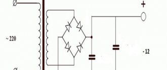
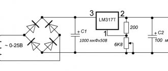
Rectifier
So, let's look at the rectifier circuit.
Well, here everything is simpler and almost on your fingers. Considering that we know what voltage we need to supply to the stabilizer - 17 volts, let's calculate the voltage on the secondary winding of the transformer. To do this, let's go, as in the beginning - from the tail. So after the filter capacitor we should have a voltage of 17 volts.
Considering that the filter capacitor increases the rectified voltage by 1.41 times, we get that after the rectifier bridge we should get 17/1.41 = 12 volts
. Now let’s take into account that we lose about 1.5-2 volts on the rectifier bridge, therefore, the voltage on the secondary winding should be 12+2=14 volts. It may well happen that such a transformer will not be found, don’t worry - in this case you can use a transformer with a voltage on the secondary winding of 13 to 16 volts.
Let's move on. Let's determine the capacitance of the filter capacitor.
Cf=3200In/UnKn
where In is the maximum load current, Un is the load voltage, Kn is the ripple factor.
In our case, In = 1 Ampere, Un = 17 volts, Kn = 0.01.
Cf=3200*1/14*0.01=18823.
However, since there is also a voltage stabilizer behind the rectifier, we can reduce the calculated capacitance by 5...10 times. That is, 2000 uF will be quite enough.
All that remains is to choose rectifier diodes or a diode bridge.
To do this, we need to know two main parameters - the maximum current flowing through one diode and the maximum reverse voltage, also through one diode.
The required maximum reverse voltage is calculated as follows:
Uarr max=2Un, that is, Uarr max=2*17=34 Volts.
And the maximum current for one diode must be greater than or equal to the load current of the power supply. Well, for diode assemblies, reference books indicate the total maximum current that can flow through this assembly.
Well, that seems to be all about rectifiers and parametric stabilizers. Ahead we have a stabilizer for the laziest - on an integrated circuit and a stabilizer for the most hardworking - a compensation stabilizer.
<<—Part 1—Part 3—>>
| What do you think of this article? | Did this device work for you? | |
| 81 | 1 | 7 |
| 7 | 1 |
Application
A power supply with or without do-it-yourself adjustment, with a secondary output of 5-12 Volts, is used to connect various electrical devices to a 220 V household electrical network.
Most often this is:
- Various personal computers (stationary, with a built-in unit, and laptops, tablets, netbooks, pocket PCs);
- Gadgets (smartphones, audio and video players, cell phones, video cameras and other devices that have a battery in their design);
- Hand-held portable power tools (screwdrivers, grinders, drills, blowers, etc.);
- Various other devices designed for low voltage, capable of operating without being connected directly to a household electrical outlet (LED lamps, shavers, car radios, radios)
Assembling the device
Prepare all the necessary parts in advance: microcircuits, transformers, diode bridge, inductor, protection unit, capacitor filter, voltage stabilizer.
Typically, the windings of transformers can withstand voltages up to 250 W. If you make a secondary winding, it conducts voltage up to 50 W. The winding can be purchased at a special store or removed from an old electrical appliance.
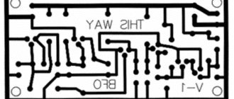
In order to make a huge number of electrical tracks, you will need a microcircuit marked PDIP-8.
To get a diode bridge, you will need four 0.2x0.5 mm diodes. The protection unit can be made from fuses (you will need two) of the FU2 brand.
- How to fix a laptop that won't charge
Insulated dielectric screwdrivers up to 1000V - tips on how to choose the best manufacturer
Dielectric insulated tool for work - which one is better to choose? Review of manufacturers, photos + video
To connect all spare parts, use a special diagram and instructions, which describe everything in an extremely accessible way.As soon as these products operate, a current of 0.16A will be generated. To make your own chokes, take magnetic ferrite.
Often, after dry diagrams there may be a photo of homemade devices, which clearly shows the design. Additionally, you can also find diagrams on how to repair the power supply if it breaks.
Accessories
To assemble a 12 Volt power supply circuit we will need:
- Thermistor;
- Capacitors (2 pcs.);
- Diode bridge;
- Drivers;
- Transformer;
- Diodes for output;
- Field effect transistors;
Checking operation under load
After installing and assembling the power supply, you need to make sure that everything is done correctly. To do this you need:
- Connect the load to the output of the power supply. Any gadget will do;
- Connect the power supply to the mains.
If the device (gadget) connected to the power supply begins to charge, then the circuit is assembled correctly and is fully operational.
Unusual power supply
Sometimes you need an adjustable power supply in the range from 0 to 30 V. Such a power supply is called a laboratory power supply. It is assembled in the following sequence:
- We install parts on the printed circuit board that can regulate the voltage (fuse, stabilizer and resistors);
- We install filter capacitors. For smooth voltage regulation.
- We connect power transistors;
- Connect power for peripherals and LM301;
- We install an operational amplifier and parts capable of stabilizing the current (resistors, capacitors, diodes);
- We install LM113 or LMV431 (zero) and protective diodes;
- Setting up the maximum current limiter;
- We connect the voltammeter
DIY 0-30 Volt power supply assembled. All that remains is to connect it to the network and test it under load. And if the circuit is assembled correctly and no errors are made, then it will definitely work.
DIY fan: how to make a homemade powerful fan. Basic parameters and properties of fans (130 photos)- Why do you need a security alarm, what functions does it perform?
How to choose winter workwear and not make a mistake - recommendations from the pros
Device information
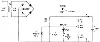
In life, situations very often arise when you need a device such as a power supply. This product can power many electrical appliances. Of course, in such a situation, you can use various analogues, for example, car batteries. But they have a big drawback, which is the supply of a constant voltage of 12 V. And this is not enough to power standard household equipment. An excellent solution in such situations would be to use a pulse current converter (regulated power supply). The peculiarity of such a device is the ability to convert the existing voltage, for example 12 V, into the one we need - 220 V. This became possible thanks to a special operating principle. It consists of converting the alternating voltage available in the network with a frequency of 50 Hz into a similar rectangular type. After this, the voltage is transformed to achieve the required value, rectified and filtered. The operating diagram of such a device is as follows.
Scheme
The power supply has increased power (thanks to the transistor) and can simultaneously act as a switch and a pulse transformer, converting current voltage. Note! The efficiency of the power supply (regulated type) is increased by the frequency rise input. Its increase makes it possible to significantly reduce the weight and size of the steel core used inside the product. Switching type power supply can be of two types:
- controlled from outside. This power supply is used in most electrical appliances;
- pulse-type self-generators.
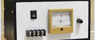
Factory model
The assembly diagram for each type of power supply will be different. At the same time, produced serial models may have different power ratings and dimensions. It all depends on the specifics of their use.
Factory devices of this type operate in the frequency range from 18 to 50 kHz. But such a model can be made with your own hands if desired. Some electronics hobbyists can even repurpose an old power supply to meet new needs. For beginners, there is a simple scheme that will allow even a completely inexperienced person to cope with it. Such a modification will be in no way inferior in quality and technical parameters to the purchased model.