The full-wave rectifier is more common than the half-wave rectifier, this is due to the numerous advantages of such a circuit. To explain exactly what the advantage is, we should turn to the theoretical foundations of electrical engineering.
First of all, let's look at the difference between a full-wave rectifier and a half-wave rectifier; to do this, you need to understand the operating principle of each of them. Examples of circuits with oscillograms will give a clear idea of the advantages and disadvantages of these devices.
Half wave converter
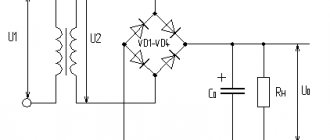
Below is a typical diagram of such a device with a minimum of elements.
Scheme: the simplest converter
Designations:
- Tr – transformer;
- DV valve (diode);
- Cf – capacitance (plays the role of a smoothing filter);
- Rn – connected load.
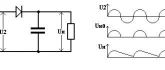
Now let's look at the oscillogram at control points U1, U2 and Un.
Oscillogram taken at control points U1, U2 and Un
Explanation:
- control point U1 displays a diagram taken at the device input;
- U2 – diagram in front of the capacitive smoothing filter;
- Un – oscillogram at the load.
The timing diagram clearly shows that after the valve (diode), the rectified voltage is represented in the form of characteristic pulses consisting of positive half-cycles. When such a pulse occurs, the charge of the capacitive filter accumulates, which is discharged during the negative half-cycle, this allows the pulsations to be somewhat smoothed out.
The disadvantages of such a scheme are obvious - it is low efficiency, due to the high level of ripple. But despite this, devices of this type find their use in circuits with low current consumption.
DIY voltage converter
Buying a voltage converter does not always seem logical. The cost of the device can be significant. Therefore, many people prefer to collect them with their own hands. Radioelements are extracted from power supplies of computers and other devices. However, it is undesirable to connect equipment sensitive to voltage changes to the simplest element.
Pulse converter circuit
Operating principle of a full-wave circuit
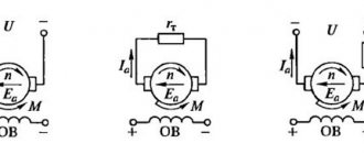
Let's consider two options for implementing a full-wave converter (rectifier): balanced and bridge. The diagram of the first is shown in the figure below.
The simplest uncontrolled balanced converter using two diodes using a transformer with a middle output
Elements used:
- Tr is a transformer that has two identical secondary windings (or one with a tap in the middle);
- DV1 and DV2 – valves (diodes);
- Cf – capacitive filter;
- Rn – load resistance.
For clarity, let us immediately present an oscillogram at control points.
Diagram of a balanced type device
- U1 – input oscillogram;
- U2 – graph in front of the capacitive filter;
- Un – diagram at the device output.
This circuit is two combined half-wave converters, that is, two separate sources account for one common load. The result of the operation of such a device is clearly demonstrated by graph U2. It shows that both half-cycles are used in the process, which gives these converters their name.
The oscillogram clearly demonstrates the advantages of such a device, namely the following facts:
- the ripple frequency at the device output doubles;
- reducing the “dips” between pulses allows the use of a smaller filter capacitance;
- A push-pull converter has greater efficiency than a half-wave converter.
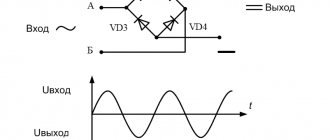
Now let's look at the bridge type, it is shown in the figure below.
Diagram: Example of using a diode bridge
The oscillogram of a bridge type device is practically no different from a balanced one, so there is no point in presenting it. The main advantage of this scheme is that there is no need to use a more complex transformer.
Video: Full-wave rectifier bridge
Converters that use a semiconductor diode bridge are widely used both in electrical engineering (for example, in welding machines, where the rated current can reach up to 500 amperes) and in radio electronics, as a source for low-current circuits.
Note that in addition to semiconductor diodes, you can also use vacuum diodes - kenotrons (an example of a circuit diagram of such a device is shown below).
Scheme: converter based on a 6Ts4P two-anode kenotron
Actually, the presented circuit is a classic implementation of a full-wave balanced converter. Today, vacuum diodes are practically not used; they have been replaced by semiconductor analogues.
1.2.4 Recommendations for performing preliminary calculations
The resistance of the load resistor is calculated by the formula
The capacity of the smoothing capacitor for a half-wave rectifier (Fig. 1.2.7) is calculated using the approximate formula
.
Here is the voltage frequency of the AC voltage source ( = 50 Hz); — pulsation coefficient (in relative units).
The capacitance of the capacitor for a full-wave rectifier is half as much:
.
In a secondary power supply with a parametric stabilizer, it is advisable to select the voltage at the rectifier output approximately twice as high as the load voltage. If a bridge rectifier is used, the resistance of the ballast resistor is found by the formula
.
Here is the voltage of the zener diode in breakdown mode, is the voltage of the open diode, is the minimum current of the zener diode. In a circuit with a parametric stabilizer, the capacitance of the smoothing capacitor is calculated using the formula
Now such power sources are used in scientific laboratories, in elementary particle detectors, in medical equipment (Chizhevsky's chandelier) and in self-defense weapons (taser). When repeating similar designs and selecting parts, you should take into account the operating voltage of both diodes and capacitors based on the voltage you want to obtain. The entire multiplier, as a rule, is filled with a special compound or epoxy resin to avoid high-voltage breakdowns between circuit elements.
Back at the beginning of the twentieth century, there was a very fundamental dispute between the luminaries of electrical engineering. Which current is more profitable to transmit to the consumer over long distances: direct or alternating? The scientific debate was won by supporters of the transmission of alternating current through high-voltage lines from the substation to the consumer. This system has been accepted all over the world and is still being used successfully.
But most electronic equipment, not only household, but also industrial, is powered by direct voltages, and this led to the creation of an entire branch of electrical engineering - the conversion (rectification) of alternating current. After the vacuum tube was forgotten, the semiconductor diode became the main element of any rectifier.
The circuit design of rectifiers is very extensive, but the simplest is the half-wave rectifier.
Half-wave rectifier.
The voltage from the secondary winding of the power transformer is supplied to one single diode. Here's the diagram.
That's why the rectifier is called half-wave. Only one half-cycle and a pulse voltage is obtained at the output. Its shape is shown in the figure.
The circuit is simple and does not require a large number of elements. This affects the quality of the rectified voltage. At low frequencies of alternating voltage (for example, as in the mains - 50 Hz), the rectified voltage turns out to be highly pulsating. And this is very bad.
An example of using a half-wave rectifier would be a simple cell phone charger. Since the charger itself is low-power, it uses a half-wave circuit, both in the input network rectifier 220V (50Hz) and in the output rectifier, where it is required to rectify high-frequency alternating voltage from the secondary winding of the pulse transformer.
The undoubted advantages of such a rectifier include a minimum of parts, low cost and simple circuit solutions. In conventional (non-switching) power supplies, full-wave rectifiers have been successfully operating for many decades.
Full-wave rectifiers.
The following figure shows a typical full-wave rectifier circuit with a midpoint.
The magnitude of the ripple of the rectified voltage is less than that of a half-wave rectifier and the size of the filter capacitor can also be used much less. You can clearly see how a full-wave circuit works in the figure.
As you can see, at the output of the rectifier there are already two times fewer voltage “dips” - those same ripples.
The rectifier circuit with a midpoint is actively used in the output rectifiers of switching power supplies for PCs. Since the secondary winding of a high-frequency transformer requires a smaller number of turns of copper wire, it is much more efficient to use this particular circuit. Diodes are used in double diodes, i.e. those that have a common body and three terminals (two diodes inside). One of the terminals is common (usually the cathode). In appearance, a dual diode is very similar to a transistor.
The bridge circuit has gained the greatest popularity in household and industrial equipment. Take a look.
It can be said without exaggeration that this is the most common scheme. In practice, you will meet her more than once. It contains four semiconductor diodes, and, as a rule, an RC filter or only an electrolytic capacitor is installed at the output to smooth out voltage ripples.
The voltage doubling rectifier is of great interest.
Voltage doubling rectifier.
The principle of the Latour-Delon-Grenacher voltage doubler is based on the alternate charge and discharge of capacitors C1 and C2 with half-waves of the input voltage of different polarity. As a result, a voltage twice the input voltage arises between the cathode of one diode and the anode of the second diode. Scheme for the studio :)
The development of the circuit was the creation of a multiplier based on semiconductor diodes.
Voltage multiplier.
Each diode and capacitor form a “link” and these links can be connected in series to obtain a voltage of several tens of kilovolts. Of course, for this the input voltage must also be large enough.
The figure shows a four-bar multiplier and at the output we get a voltage four times higher than the input ( U ). These rectifiers have become widespread where it is necessary to obtain high voltage at a fairly low current. For example, high-voltage sources in old televisions and oscilloscopes were made using this scheme to power the anode of a cathode ray tube.
Now such power sources are used in scientific laboratories, in elementary particle detectors, in medical equipment (Chizhevsky's chandelier) and in self-defense weapons (taser). When repeating similar designs and selecting parts, you should take into account the operating voltage of both diodes and capacitors based on the voltage you want to obtain. The entire multiplier, as a rule, is filled with a special compound or epoxy resin to avoid high-voltage breakdowns between circuit elements.
For the normal operation of some devices, such as the Chizhevsky chandelier, sufficiently high voltages are required. According to experts, a negative air ion emitter is effective only at a voltage of at least 60 kilovolts.
Three-phase rectifiers.
The ripple coefficient at the load is very small, which allows the use of filter capacitors of small capacity and small dimensions.
More complex is Larionov’s scheme, which is called “three half-bridges in parallel,” which is clearly visible from the figure.
The circuit already uses six diodes and a slightly different switching circuit. In general, there are quite a lot of three-phase rectifier circuits, and the most advanced, although rarely used, is the “six bridges in parallel” circuit, which is already 24 diodes! But this circuit can produce high voltage at high power.
Three-phase powerful rectifiers are used in electric locomotives, urban electric transport (trams, trolleybuses, metro), and in industrial installations for electrolysis. Also, industrial systems for purifying gas mixtures, drilling and welding equipment use three-phase rectifiers.
Now you know what types of AC rectifiers there are and can easily find them on the circuit diagram or printed circuit board of any device. And for those who want to know more, we recommend that you read the book “Semiconductor Rectifiers”.
A full-wave zero-point rectifier can be thought of as two half-wave rectifiers operating alternately to drive a common load.
Full-wave rectifier circuit with zero point.
A full-wave zero-point rectifier can be thought of as two half-wave rectifiers operating alternately to drive a common load.
In this circuit, each of the diodes conducts current only during that part of the period when the anode is at a higher potential relative to the cathode, in which case the diode is open.
During the period of input voltage u 1 or secondary voltage u 2 in one half-cycle, diode VD1 conducts current i' 2, and in the other half-cycle, diode VD2 conducts current i" 2. As a result, the time diagrams of currents and voltages take on the form shown in Figure 7.6.
full-wave circuit is significantly reduced, since the ripple coefficient in this case is equal to:
Despite the different images, the electrical connection remains the same, and yet the first option is used much more often, so we will stick to it.
In one of the recent articles, we dealt with the design and operating principle of a half-wave rectifier, so today we will continue this topic! And let’s move on, as we planned, to a more complex rectifier circuit, and at the same time the most popular. We are talking, of course, about a full-wave rectifier , the heart of which is a diode bridge .
A diode bridge is an electronic device that is specifically designed to solve the problem of current rectification. The inventor of this scheme is the German physicist Leo Graetz, so you can also find the name Graetz bridge, which is very logical
A basic diode bridge consists of 4 diodes connected as follows:
But often on circuit diagrams you can find a simplified designation:
Actually, let's look directly at the full-wave rectifier circuit :
Some variations are also possible here, for example:
Despite the different images, the electrical connection remains the same, and yet the first option is used much more often, so we will stick to it.
Resistor R_н in this example plays the role of a payload. As when analyzing a half-wave rectifier, let’s consider the case with a sinusoidal voltage at the input:
In the case of a positive half-cycle of the signal (U_ gt 0), current will flow through diodes D1 and D3. Let's look at the current path more clearly:
And on the negative half-cycle, on the contrary, diodes D1 and D3 will be closed, and the current flow will be provided by D2 and D4:
In both cases, the current through the load will flow in the same direction, from the point marked “+” in the diagram to the point “-”. And this is precisely why we use a rectifier - so that current flows through the load in only one direction! And as a result, the output signal looks like this:
The difference from the half-wave circuit is immediately obvious, when the output signal was only for one half-cycle. In this case, the current flows through the load in both positive and negative half-cycles! Therefore, the circuit is called two half-wave.
But! Just as in the case of a half-wave rectifier, we get a pulsating current at the output, and not a strictly constant one. Therefore, it is necessary to use an anti-aliasing filter, which in its simplest form can consist of a single capacitor:
The capacity should be such that the capacitor does not have time to discharge quickly. So, we add a capacitor to the rectifier circuit on the diode bridge and check the voltage across the load:
It's a completely different matter!
There are special diode assemblies , which consist of four diodes with identical characteristics, connected via a bridge circuit, placed in one housing. Accordingly, such an assembly has four pins, all exactly as in our diagram. Terminals intended for connection of alternating current (input signal) may be indicated by the symbol “
” or the letters AC, traditional for alternating current. The terminals to which the load is connected are designated “+” and “-“. But all this, of course, is individual and depends on the device used.
Several examples of diode bridges in an assembly:
And according to tradition, at the end of the article, we summarize the pros and cons of a full-wave rectifier compared to a half-wave rectifier:
- First of all, since both half-cycles of the signal are already used here, then, naturally, the efficiency of the circuit is greater.
- In addition, the pulsating voltage at the output has a frequency that is 2 times higher, and such ripples are easier to smooth out.
But, as always, there are also disadvantages:
And this is definitely where we end for today. Thank you all for your attention, any questions can be asked on our forum, in the VKontakte group or in the comments to the article!
The area under the integral curve is:
Fig.1. Half-wave rectifier circuit.
Rectifier (electric current) - converter of electrical energy; a mechanical, electrovacuum, semiconductor, or other device designed to convert an alternating input electrical current into a direct output electrical current. [12]
Most rectifiers create not constant, but pulsating unidirectional voltage and current, and filters are used to smooth out the ripples.
A device that performs the opposite function - converting constant voltage and current into alternating voltage and current - is called an inverter.
Due to the principle of reversibility of electrical machines, a rectifier and an inverter are two varieties of the same electrical machine (true only for an inverter based on an electrical machine).
These rectifiers are also used to provide power in surveillance and alarm systems. In the low power range they are used for charging starter batteries of diesel engines and gas turbines.
The principle of operation of the rectifier is obvious from the above figure. Self-starting circuit - the operational amplifier (op-amp) is powered by rectified voltage.
24.Purpose, circuit and operating principle of a full-wave rectifier with a midpoint
In the event that when rectifying alternating current it is necessary to use both
half-cycle, then we will need a completely different type of rectifier.
This circuit is called a full-wave
rectifier.
One variation of the full-wave rectifier, called a midpoint rectifier
, uses a midpoint-tapped secondary transformer and two diodes, as shown in the figure below.
Mitkevich rectifier “two quarter-bridges in parallel” on a two-anode lamp. Here the secondary winding H serves to heat the cathode of the lamp.
Full-wave rectifier with midpoint
The operating principle of this circuit is easy to understand by analyzing each half-cycle separately. First, let's look at the first half-cycle, when the source voltage is positive (+) at the top and negative (-) at the bottom. At this moment, only the upper diode conducts, and the lower one blocks the current, and, therefore, the load “sees” only the first half-cycle of the sine wave. During this part of the cycle, current flows only through the upper half of the transformer secondary winding (see figure below).
in this rectifier, the rectified half-cycles have a bell-shaped shape, that is, a shape close to the function.
The area under the integral curve is:
The relative equivalent active internal resistance is equal to , that is, twice as much as in a single-phase full-bridge, therefore there is more energy loss for heating the copper of the transformer windings (or copper consumption).
25.Purpose, circuit and operating principle of a full-wave bridge rectifier
Operating principle of a full-wave bridge rectifier A full-wave bridge rectifier consists of a transformer Tr and four diodes connected to the secondary winding of the transformer via a bridge circuit. The secondary winding of the transformer is connected to one of the diagonals of the bridge, and the load resistor Rн is connected to the other. Each pair of diodes D1, D3 and D2, D4 operates alternately.
Most rectifiers create a pulsating current rather than a direct current; filters are used to smooth out the pulsations.
How to organize bipolar power supply
By combining a balanced circuit and a bridge circuit, you can get a converter that will provide bipolar power at the output with a common (zero) point. Moreover, for one it will be negative, and for the other it will be positive. Such devices are widely used in power supplies for digital radio technology.
Diagram: example of a converter with bipolar output
Full-wave rectifier with zero terminal
A rectifying device with two diodes converts both half-waves of the signal supplied to it into a pulsed direct current. To convert the current, a transforming device is used, in which the secondary winding is divided into two halves. The central area is connected to the ground.
Principle of operation:
- With a positive half-cycle, a plus appears on one part of the transformer turns, and a minus on the second. The valve, which is connected to the positive part, conducts current. The second diode is closed. Passing through the resistor, the current hits the central point;
- With a negative half-cycle, the state of the windings changes. The second diode conducts current.
As a result, electricity is passed during both half-waves, and the efficiency reaches 90%.
How to implement voltage doubling
Below is a circuit that allows you to obtain a voltage at the output of the device that is twice as high as the original one.
Voltage doubling circuit
It is typical for such a device that two capacitors are charged in different half-cycles, and since they are located in series, then, as a result, the total voltage at “Rn” will be twice as high as at the input.
In a converter with such a multiplier, transformers with a lower secondary winding voltage can be used.
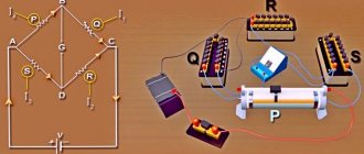
Bridge Circuit Operation
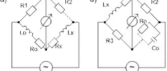
Understanding electrical measuring instruments
The device consists of four semiconductor gates combined into a bridge. In this case, the secondary winding of the transforming device is combined with the opposite arms of the diode bridge. The load resistors will be connected via other shoulders. In this case, the output characteristics are significantly higher than those of two-period ones, due to the flow of the entire wave of alternating current voltages through the device.
During the positive half-wave, the signal moves from the negative part of the secondary winding of the transforming device through the valves and load resistor to the positive part of the set of turns of the transforming device. With a negative half-wave, the process occurs in the reverse order.
Using Op Amps
As is known, the current-voltage characteristic of diodes is nonlinear; by creating a single-phase precision (high-precision) full-wave rectifier on an op-amp chip, the error can be significantly reduced. In addition, it is possible to create a converter that allows you to stabilize the current on the load. An example diagram of such a device is shown below.
Circuit: a simple op-amp stabilizer
The figure shows a simple current stabilizer. The op amp used in it is a voltage controlled source. This implementation makes it possible to ensure that the current at the output of the converter does not depend on the voltage loss across the load Rн and the diode bridge D1-D4.
If voltage stabilization is required, the converter circuit can be slightly complicated by adding a zener diode to it. It is connected in parallel to the smoothing capacitance.
Diode bridge
A full-wave rectification circuit, called a diode bridge, uses four valves to form a closed circuit. A current generator is connected on one part, and a resistor on the other.
When connecting the capacitor winding, the valves operate in pairs, smoothing out the positive and negative half-waves. Only positive remains at the output, while the ripple indicator is 0.48.
The main advantages of the diode bridge circuit are simplicity and high efficiency. The disadvantages include a decrease in voltage on the valves, which affects the efficiency of low-voltage systems.
Briefly about controlled converters
It is often necessary to control the voltage at the output of the converter without changing the input. For this purpose, the most optimal would be to use controlled valves; an example of such an implementation is shown below.
Simple thyristor converter (on controlled valves)
Full-Wave Rectifier Voltage Filtering
The output we get from the full wave rectifier is a pulsating DC voltage that increases to a maximum and then decreases to zero.
To obtain a ripple-free voltage, we need to filter the output signal. One way to do this is to connect a capacitor, known as a smoothing capacitor , across a load resistor, as shown below:
Initially the capacitor is not charged. During the first quarter of the cycle, diode D1 is forward biased, so the capacitor begins to charge. Charging continues until the voltage reaches its peak value. At this moment, the voltage across the capacitor will be equal to Vp.
After the input voltage reaches its peak, it begins to decrease. As soon as the input voltage becomes less than Vp, the voltage across the capacitor will be higher than the input voltage, which will close the diode.
When the diode is not conducting, the capacitor discharges through the load until the next peak is reached. When the next peak occurs, diode D2 briefly opens and charges the capacitor to the peak value.
Three phase rectifier
We looked at various implementations of single-phase full-wave converters, but similar devices are also used for three-phase sources. Below, as an example, a device created according to Larionov’s scheme is shown.
An example of the implementation of a Larionov circuit Oscillogram at the output of a Larionov circuit
As the graph above shows, the implementation of a bridge circuit between pairs of phases allows for minor ripples to be obtained at the output. Thanks to this, the filter capacity can be significantly reduced, or even dispensed with.
Video
Coffee capsule Nescafe Dolce Gusto Cappuccino, 3 packs of 16 capsules
1305 ₽ More details
Coffee capsules Nescafe Dolce Gusto Cappuccino, 8 servings (16 capsules)
435 ₽ More details
SSD drives
Design
Calculating even a simple full-wave converter is not an easy task. It can be significantly simplified using special software. We recommend choosing the Electronics Workbench program, which allows you to perform schematic modeling of analog and digital electrical devices.
By simulating a full-wave rectifier in this program, you can get a clear idea of the principle of its operation. Built-in formulas allow you to calculate the maximum reverse voltage for diodes, the optimal capacity of the quenching capacitor, etc.
Transformer circuit with double winding and common terminal
The principle of operation is that during the positive half-wave the same voltage is generated. At this time, the lower valve remains closed under the influence of a negative signal, while the upper valve opens. Thus, electric current flows from it.
During the negative part of the half-wave, the upper gate diode is in the closed state due to the voltage flowing to the cathode from the lower valve, which is open due to the positive signal arriving at the anode. In this case, both half-waves work.