Don't want to buy an antenna for the DVB-T2 terrestrial standard? We'll tell you how to quickly make a homemade one from scrap materials.
It is not at all necessary to buy antennas suitable for terrestrial digital television of the DVB-T2 standard, especially since the cost of the device together with a digital receiver can amount to a decent amount. Moreover, such an antenna must be suitable for the parameters of the frequency range that is used in the area where you live. Otherwise, the multiplex used in the antenna will not receive all available TV channels.
We will tell you how to find out the frequency range of your region and calculate the parameters of the desired antenna. Also, our step-by-step instructions will help you quickly make a high-quality antenna from scrap materials for receiving over-the-air channels of the new digital standard DVB-T2.
For reference:
Multiplex (from the English multiplex - mixture, mixed; also mux) - combining television channels into a single digital package for digital television broadcasting
Antenna efficiency
The antenna will work without an amplifier.
Signal reception is ensured due to the design of the receiver. The form is designed in such a way that you can set up digital TV channels on your TV.
The design is primitive, so to receive an over-the-air signal you need:
- so that the power of the incoming signal to the antenna is at a high level:
- the repeater must be located near your current location;
- there should be no obstacles on the signal path (tall buildings, hills, etc.);
- so that the signal is present at all. There are areas where the digital terrestrial television signal does not arrive at all. Then, no matter what the antenna is, it will not be possible to tune the channels on the TV receiver.
Characteristics
The most optimal sizes are considered to be from six to eight millimeters. You also need to take into account resistance, flexibility and shielding index. Of the imported ones, RG-59 and also RG-6 are quoted. In the city, you can also use the domestic brand RK-75, since the transmitters are located quite close to each other. For other conditions it is not acceptable - the degree of attenuation is too high.
If the cable runs along the electrical wiring, then it is more effective to use a ten-millimeter diameter. It has better noise immunity.
Moreover, the winding should be tight and the flexibility should be small. When studying the product passport, it is necessary to ensure that there is a value of lower attenuation, which indicates a higher quality of the product.
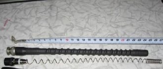
Required materials and tools
- Coaxial cable with a resistance of 75 ohms. The cable length is not that important. But it is better to choose the shortest possible cable, since with every meter the signal attenuates. As a result, the TV receives less signal and may have problems displaying channels. There may be freezes, “No signal” messages, or the appearance of squares.
- Use a utility knife or other cutting tool to strip certain parts of the cable.
- Pen or marker for marking cables. The parts that need to be stripped of cable insulation will be marked.
- RF connector with adapter (plugs) to insert the cable into the antenna connector of the TV.
- Pliers. The tool is optional, but will help make the contact more tightly at the last antenna connection.
- Wood (plywood). After manufacturing, the antenna needs to be shaped into a ring (loop). The cable is subject to change in shape due to natural reasons. Therefore, it is better to fix the loop on a wooden frame so that the shape remains unchanged even under the influence of external factors (strong wind).
Selecting a TV plug
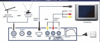
In order to have a constant high-quality connection to the TV, whether to a cable broadcast network, or to an antenna, you need to purchase a television cable and F-plugs. The task may look simple, but if done incorrectly, the image quality may be unstable and of poor quality.
When buying a television cable, you should correctly understand its structure: in its very center there is a wire made of copper or steel, which is covered with a layer of copper during manufacturing. On top there is insulation made of a material that does not conduct electric current. Next comes the shielding material, and on top of it there is an aluminum braid, which serves as the second conductive material. You should choose not only a high-quality TV and related equipment, but also peripheral tools: cable and connectors.
An expensive cable differs from a cheap one by the presence of an additional aluminum braid. Cheaper models use only copper. Also a big plus will be the presence of a dense, hermetically sealed sheath that protects the wire from adverse environmental conditions.
How to connect the antenna plug correctly so that the current flow is problem-free and the picture quality is high? This may not be the easiest task. The current flow in an electrical network and a television cable is different. The latter carries a high-frequency current, which is why sometimes even a thin layer of silver or gold is used in the coating.
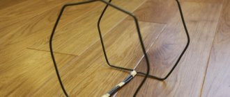
Making a “loop” with your own hands
The manufacturing process consists of several stages:
- cable marking (marks are made at exact distances so that stripping can be done later);
- short circuit of the antenna cable at the end stripping point;
- Installing an antenna plug to connect the cable to the antenna input of the TV.
How to mark the cable
- From any free end of the cable, the first mark is made after 5 cm.
- Then another 22 cm is measured and a 2 cm section is marked.
- Then a centimeter section is again marked at a distance of 22 cm from the last mark.
Marking scheme
Proper stripping
- The first 5 centimeters of the cable are completely cleared of insulation. Both the external insulation and the internal one, which protects the core, are removed. A connection (twisting) of the shielding layer with the core is made.
1
2
3 - In the second section, the outer insulating layer along with the shielding layer is removed.
It is important to be careful not to damage the internal insulation. In the future, damage to the insulation may cause the inner core to break.
- In the third section, only the top insulation is removed, the screen is not touched.
Next, the first stripped section is screwed onto the last one. Twisting is done by hand. Additionally, you can use pliers to press the contact.
Afterwards we try to give the shape of the loop as accurately as possible.
By the way, the antenna was called “loop” because of its shape.
RF Connector Installation
The cable is connected to the antenna connector of the TV receiver through an adapter. It, in turn, is screwed into the RF connector. The latter must be correctly placed on the other end of the cable.
- Remove the top layer approximately 1 cm long.
- We bend the foil layer and copper braid back onto the cable itself.
- The internal insulation is removed. You can remove it completely by the same 1 cm, but it is better to leave at least 2-3 mm to prevent the screen from shorting to the cable core.
- Screw the connector onto the cable. If it is difficult to do this with your hands, you can carefully clamp the connector with pliers and screw it on. Be careful, as modern connectors are made of brittle metals. There is a high risk of the metal cracking. You'll have to buy a new connector.
- The connector must be inserted so far that the cable core is fully visible (refer to the figure below).
- An adapter is screwed into the connector using a thread. It will be inserted into the antenna input on the television receiver.
Selecting a cable for your TV
The connection from your antenna to your TV is as important as the antenna itself. A high quality coaxial cable is used for this. First, let's understand what a coaxial cable is and what components it consists of.
First of all, this is the wire through which radio or television signals are transmitted. It is they that distributors use to transmit television networks to individual homes, which is why this service is called cable television.
Their distinct thick, round shape is due to a thick layer of internal insulation, which is designed in part to reduce the effect of magnetic fields on the signal carried by the cable, as well as to reduce the amount of signal loss that occurs when signals travel through long lengths of coaxial cable.
Structurally, a coaxial cable consists of four layers:
- The central wire, which has a perfectly round and cylindrical shape;
- A thick layer of insulation made of plastic or other inert non-conductive material;
- The outer thin layer of metal casing (braid), which also carries the signal;
- An outer layer made of thick plastic designed to protect the metal casing.
The signal carried by a coaxial cable is transmitted simultaneously through the central wire, as well as through a separate metal braid. This is done because both conductors generate a magnetic field, just like any electrically charged wire. However, when two oppositely charged magnetic fields come into contact with each other, the fields cancel each other out. This allows cables to be placed near other sensitive electronic equipment and metal objects without fear of the cables acting as magnets on each other.
Read also: Do-it-yourself cross feed on a lathe
All a coaxial cable has to do is just two things:
- Receive the signal from the antenna towards the receiver;
- Conduct the received signal from the transmitter to the antenna without loss of quality.
It is very convenient that there are no complications or misunderstandings in a coaxial cable: you just need to buy a cord with the least signal attenuation, determine the optimal length, wrap it on both sides - and that’s it, the connection is ready!
How can you determine which cable will have the least signal attenuation? Signal loss in a cable depends on three parameters:
- Cord lengths;
- Product type;
- Frequencies (RF channel).
As for the cable length, you should try to make the connection as short as possible. The longer the cable, the greater the signal loss. It is not possible to give universal figures, since the marking of the cable and the frequencies that your antenna receives play a role. RF channels in the VHF band have lower losses than channels in the UHF band. But we can give some characteristics based on the type of coaxial cable. Today there are two groups of such products:
- Thin - with a cord diameter of 5 mm. With their help, local connections are created over short distances, since the signal attenuation here occurs much faster, the delay is 5 ns/m;
- thick - with a diameter of about 10 mm. The design of such products is more rigid and expensive, so special equipment is required for their installation. The signal in such cables is practically not lost, and the delay in signal transmission is approximately 4.5 ns/m.
Each cable has its own marking, which is applied to each meter of the product. For example, the cable brand RK-75-2-3-2-A means the following:
- RK – radio frequency cable;
- 75 – wave impedance in Ohm (ratio of electric and magnetic fields);
- 2 – the value of the nominal diameter of the insulation in mm;
- 3 – insulation material (3 – foamed polyethylene);
- 2 – development number;
- A – purpose – antenna.
You may also encounter the following markings:
Net.on RG-6 white CCS 1.00 (15%) / FPE / Al-Pet-Al Foil Unbonded / Al 32x0.12 / PVC RW 100m, where:
- Net.on is a brand (manufacturer);
- RG-6 – radio frequency;
- CCS – Copper-Clad-Steel, that is, a copper alloy is applied thermomechanically to the top of the product;
- 1.00 – diameter of the central core in millimeters;
- 15% – conductivity coefficient of the central conductor;
- FPE – internal insulation material – foamed polyethylene;
- Al-Pet-Al Foil Unbonded – composition: the film is foiled with aluminum on both sides;
- Al 32x0.12 – characteristics of braided wire (32 aluminum wires, each of which has a diameter of 0.12 mm);
- PVC RW – external insulation material (PVC);
- 100 m – product length.
When choosing a coaxial cable for your antenna, listen to these recommendations:
- The characteristic impedance of the product for a high-quality picture should be 75 Ohms;
- The diameter of the cord must be at least 6 mm;
- Shielding coefficient – from 60 dB and above;
- The purchased products must be complete and must be labeled;
- The product must bend smoothly and not have deformations, cracks or breaks.
Most often, to connect cable television in an apartment, they buy an RG-6 cable. It is available with 2, 3 or 4 layers of shielding. Three or four layers provide better interference protection, are stronger and more durable, but are slightly more expensive and less flexible than double shielding.
The RG 6U cable is a product with a solid central core, which is galvanized with copper, and the shielding braid is made of aluminum foil and copper. This is an excellent cable option in terms of price and quality ratio.
RK-75 is an improved version of RG-6. It has similar characteristics, but this type comes with a better screen and can transmit a satellite TV signal.
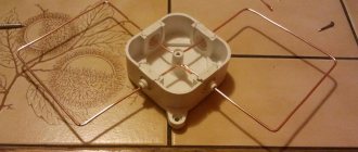
Frame manufacturing
If the antenna will be installed outside the building (on the street), then you need to build a frame. It will maintain its loop shape even when the antenna is exposed to strong winds.
You can make a frame by cutting out a ring in a similar shape to the antenna from plywood or any other material. The cable is then secured to the ring with electrical tape, tape or clamps.
You can also attach a mast - a long stick - to the frame to secure it on the street.
Loop from a pipe
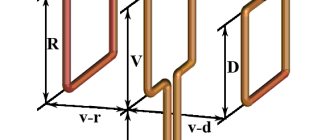
This do-it-yourself antenna for a summer residence is a little more difficult to manufacture: you need a pipe bender, but the reception radius is larger - up to 40 km. The starting materials are almost the same: metal tube, cable and rod.
The bend radius of the pipe is not important. It is necessary that the pipe has the required length, and the distance between the ends is 65-70 mm. Both “wings” should be the same length, and the ends should be symmetrical about the center.
Homemade antenna for a TV: a TV signal receiver with a reception radius of up to 40 km is made from a piece of pipe and cable (to increase the size of the picture, click on it with the left mouse button)
The length of the pipe and cable is indicated in the table. Find out what frequency the repeater closest to you is broadcasting on, select the appropriate line. Saw off a pipe of the required size (diameter is preferably 12-18 mm, the parameters of the matching loop are given for them).
| Channel number | Channel frequency | Vibrator length - from one end to the other, cm | Cable length for matching device, cm |
| 1 | 50 MHz | 276 cm | 190 cm |
| 2 | 59.25 MHz | 234 cm | 160 cm |
| 3 | 77.25 MHz | 178 cm | 125 cm |
| 4 | 85.25 MHz | 163 cm | 113 cm |
| 5 | 93.25 MHz | 151 cm | 104 cm |
| 6 | 175.25 MHz | 81 cm | 56 cm |
| 7 | 183.25 MHz | 77 cm | 53 cm |
| 8 | 191.25 MHz | 74 cm | 51 cm |
| 9 | 199.25 MHz | 71 cm | 49 cm |
| 10 | 207.25 MHz | 69 cm | 47 cm |
| 11 | 215.25 MHz | 66 cm | 45 cm |
| 12 | 223.25 MHz | 66 cm | 44 cm |
Assembly
The tube of the required length is bent, making it absolutely symmetrical relative to the center. One edge is flattened and welded/sealed. Fill with sand and seal the other side. If there is no welding, you can plug the ends, just attach the plugs to good glue or silicone.
The resulting vibrator is mounted on a mast (rod). The central conductors of the matching loop and the cable that goes to the TV are screwed to the ends of the pipe, and then soldered. The next step is to connect a piece of copper wire without insulation to the braided cables. The assembly is completed - you can start “setting up”.
If you don’t want to do it yourself, read how to choose an antenna for your dacha here.
Setting up TV channels
After the coaxial cable antenna is made, installed and connected to the TV, you can start setting up digital television.
Settings are performed differently on different brands of TVs. But the principle of searching for channels is the same everywhere. You need to go to the channel settings menu and perform an automatic or manual search.
Before setting up, be sure to go to the manual setup item and look at the signal level scale. If the signal is weak, try playing with the antenna, placing it in a different place, raising it higher, or changing the direction.
Example of a scale on a Samsung TV
For the most accurate direction of the structure to the nearest TV tower, use the terrestrial digital television map (karta.rtrs.rf). Enter your area and house number in the search bar. Click on your home and a table of repeater characteristics will appear. Look at the compass icon. When directing, be guided by it. This way you can receive the signal most accurately.
In most cases, automatic tuning of air channels will help. If the antenna shows only 10 channels out of 20, this may indicate the following:
- There is only one multiplex broadcasting in your area. This means you can only watch 10 channels.
- The signal is very weak, so only one of the channel packages (multiplexes) is caught. In this case, a more powerful antenna will help. Some options you can do yourself. But it’s better to take a closer look at factory antennas with a built-in amplifier.
After auto-search, if not all channels are shown, try searching manually. Then you need to find out the TVC (television channel) numbers or multiplex frequencies. All data is taken from the ECTV card.
Next, search for each multiplex one by one.
Building up
How to properly extend a TV cable with your own hands? Schematically, the splicing diagram requires the presence of:
- female adapter;
- plug device;
- connections of detachable parts.
It is necessary to screw a nut onto each end to subsequently connect the plug and socket. The first is screwed onto the TV plug. The second is for the TV socket.
The next stage of work is connecting them. In order for it to be securely fastened, it is best to use electrical tape, despite the fact that the appearance is not very attractive. But the feasibility of such an action is always confirmed in practice. They can then be hidden in cable channels.
If it is inconvenient to use straight plugs during installation, you can use an angular design. This ability is especially appreciated in cases where there are complex turns.
Any method must be done in such a way that the cable is easy to get to if the need for repair arises.
We amplify the signal without an amplifier
The reception efficiency (primarily this concerns the option under consideration) can be increased without additional electronics. It is enough to install a reflector or reflective screen. It will return television waves back to the antenna field, almost doubling the level. The canvas is located at a distance of 100 mm on the opposite side of the TV tower. A prerequisite is no electrical contact. Moreover, the reflector does not have to be solid. A series of metal tubes or openwork mesh is sufficient.
You can enhance the effect by using the “double biquadrate” design. The same dimensions apply, but the range remains the same. The extra length simply increases the signal strength.