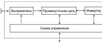
To successfully search for valuables, it is advisable to understand at least in general terms how a metal detector works and how it is designed. I could not find any meaningful material on this topic; you come across either a retelling of the Wikipedia article of the same name, or too abstruse texts and videos that are completely incomprehensible to a non-specialist. Therefore, I will try to explain as simply and clearly as possible the principle of operation of a metal detector, based on the scant available information. So let's get started.
Types of metal detectors
In principle, this point is not particularly interesting to us, because... We are only interested in ground metal detectors designed to search for coins, treasures and other valuables. But in addition to ground metal detectors, there are also military metal detectors - mine detectors, as well as inspection ones - manual (for security officers at airports and train stations) and arched (through which we pass at the same airports and train stations). As a rule, military and security metal detectors are simpler in design, because... are designed to search for any metal objects and discrimination is not important for them. Therefore, we will not dwell on them.
Arched and manual inspection metal detectors
The so-called ground can also be classified as unpaved. underwater devices characterized by a completely sealed design. As an example, we can cite any devices that allow complete immersion under water: Minelab Excalibur 2, Garrett AT GOLD, Minelab CTX 3030, Garrett Sea Hunter Mark II and others.
Minelab Excalibur 2, Garrett AT GOLD, Minelab CTX 3030, Garrett Sea Hunter Mark II
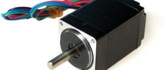
It is also worth mentioning deep metal detectors, designed to search for large metal objects at a depth of several meters. They are usually quite massive and have two coils: receiving and transmitting. Often these devices do not respond to small targets like a coin and do not discriminate. However, they are able to react not only to metal, but also to some inhomogeneities in the ground: voids, foundations and the like, which is very useful when searching for, say, treasure.
Deep metal detector
And another important point: the metal detector can be analog or digital. Digital ones are more common. They differ in their approach to signal processing. If in a digital device the signal from the coil is processed by a processor and then displayed on the screen and in the form of sound, then in an analog device the signal is immediately output to the speaker without complex processing. Accordingly, the response time of an analog device is shorter, but the functionality is noticeably weaker. In general, the issue of choosing a digital or analog metal detector deserves special attention, but that’s not the topic now.
Analog metal detector
Metal detector with electronic frequency meter
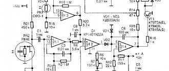
The operating principle of such a metal detector is based on an electronic frequency meter estimating the frequency of the measuring generator, when the sensor itself is still far from the target. The resulting value is “remembered” by the register. After which, in the process of searching for objects of interest, the electronic frequency meter continuously measures the frequency of the receiving generator. The reference frequency indicator is subtracted from the received data, and the result is displayed on the display screen.
Circuit diagram of a metal detector with an electronic frequency meter
Metal detectors
| [Home] | [Donate!] [Contacts] |
Metal detectors
The classic method for detecting hidden objects is to use the effect of objects made of conductive and ferromagnetic materials on the parameters of a nearby coil or system of several inductors (Fig. %img:chng_l).
Rice. %img:chng_l
It should be noted that this is not the only way. Objects made of ferromagnetic materials can also be detected by the local distortion they create in the Earth's magnetic field, which can be detected using a sensitive magnetometer. Metal detectors based on a magnetometer show very good results - large objects made of ferromagnets can be detected with their help at a depth of several meters. But they are not universal - most metals, including the most “interesting” ones - copper, silver, gold, their alloys - do not have any pronounced magnetic properties and cannot be detected in this way (cannot be detected by passive devices, but can - active, having an additional current exciter in the search objects). In this article we will consider the most universal first detection method, using a sensor - a coil.
Contents Metal detectors Operating principle Frequency-based metal detectors Induction metal detectors Transmit-receive metal detectors Pulse metal detectors
Characteristics of a metal detector Elementary theory of a metal detector Theoretical maximum detection depth See also Calculation of metal detectors using numerical analysis of eddy currents
Operating principle
It is known that a conductive object reduces the inductance of a nearby coil. The effect is somewhat similar to the effect of a short-circuited turn on a coil and is explained as follows (Fig. %img:ec1). Due to the flow of alternating current i1 through the coil L1, an alternating magnetic field ( B1 ) is created around it. Under the influence of an alternating magnetic field, eddy currents arise in nearby conducting bodies. Eddy currents, in turn, create their own magnetic field ( B2 ); the resulting field is the sum of the magnetic field of the coil and the magnetic field of eddy currents in the conducting object ( B = B1 + B2 ). As a result, the magnetic flux passing through the coil, in the presence of a conducting object nearby, turns out to be different in amplitude and phase from the magnetic flux in the absence of the object (with the same parameters of alternating current i1 through the coil). This is equivalent to changing the inductance and active resistance of the coil itself. The effect is usually extremely weak, but can be detected by precise measurements. Numerical estimates of the effect will be performed below.
Rice. %img:ec1
Objects made of ferromagnetic materials also affect the inductance of a nearby coil, increasing it. Thanks to this, they can also be detected by changes in the inductance of the sensor coil. Moreover, by the sign of the change in inductance, we can easily distinguish ferromagnetic materials from materials that are not ferromagnetic. True, if the material is both ferromagnetic and conductive (for example, iron and many of its alloys), then both effects will appear simultaneously. Which one will prevail depends on the frequency of the current in the coil, on the size and shape of the object, on the relative position of the coil and the object. In principle, even for the same object, it is possible to change the sign of the inductance deviation depending on the conditions. But at low operating frequencies for not too massive objects, one can expect the predominance of the effect of increasing inductance.
We reduced the task of searching for metal objects to the task of identifying small changes in the inductance of the sensor coil, for solving which there are several methods. Depending on the chosen solution, we will get one of the types of metal detector: metal detector - frequency meter (for example, the simplest, “on beats” or more complex - based on a digital frequency meter); induction metal detector; metal detector of the “transmit-receive” type; pulse metal detector.
Metal detectors based on frequency measurement
Probably the easiest way to detect small variations in inductance is to convert changes in inductance into changes in frequency (Figure %img:md_fm_b). To do this, the coil is included in the oscillatory circuit 1, which sets the frequency of the self-oscillator 2; deviations of the coil inductance from the initial value will lead to deviations in the generation frequency.
Rice. %img:md_fm_b
Hereinafter, it is assumed that the metal detector coil is shielded, as shown in the diagram. This is a mandatory condition, otherwise changes in the parasitic capacitance of the coil when it approaches conductive objects, including poorly conductive ones (soil, the body of the device operator himself) and even dielectrics (due to non-unit dielectric constant) will cause a response much greater than that of useful goals. The screen around the coil eliminates the influence of surrounding objects on the coil's own capacitance. The screen is made in the form of a thin-walled shell around the coil winding, always with a break so that a short-circuited turn does not form.
It can be shown that the relative change in frequency under the influence of search objects is approximately equal to half the relative change in inductance, \(\varepsilon_f \approx \varepsilon_{{}_L}/2.\) Small changes in frequency are relatively easy to detect. For example, using digital frequency measurement methods.
A purely analog implementation of a metal detector based on frequency measurements is also possible, as in “beat” metal detectors, Fig. %img:md_beat (now they are of rather historical interest). Such devices have two generators. A sensor coil is connected to one (generator 2 in the diagram) (included in the oscillatory circuit 1), the inductance of which determines the generation frequency. This oscillator also has a manual adjustment to set its initial frequency close to the frequency of the second - reference oscillator 4, which is exemplary (the adjustment function can be transferred to the reference oscillator, but then stabilization with a quartz resonator cannot be used). Signals from both generators are fed to mixer 3 (adder + detector), at the output of which we receive a signal with a difference frequency, which is amplified by amplifier 5, from where it is sent to headphones 6, and can also be fed to LED 7 to visualize low-frequency difference oscillations. By adjusting one of the generators, we achieve a signal at the mixer output with a minimum frequency. As the coil approaches the object, the frequency of the first generator shifts. The difference frequency changes by the same value in absolute value, but the relative change is large and is easy to detect even by ear.
Rice. %img:md_beat
The advantage of “beating” devices is their extreme simplicity. Such a metal detector can be assembled using literally three transistors.
The main disadvantage is low sensitivity, limited by the minimum audibly detectable frequency shift, amounting to a few hertz at best. In addition, the generators of such a metal detector, operating at close frequencies, are prone to mutual synchronization due to the presence of parasitic connections between them (through the mixer due to non-ideal isolation of the inputs, through the power supply circuits, through parasitic capacitances and mutual inductances of circuit elements). To prevent synchronization, it is necessary to increase the initial frequency detuning of the generators (the stronger the coupling between the generators, the more their frequencies must differ in order to avoid synchronization) or greatly complicate the design in order to minimize the coupling of the generators. An increase in the initial detuning reduces the already low sensitivity of the metal detector, since with an increase in the difference frequency, the value of the minimum frequency shift that can be detected “by ear” increases.
Due to their shortcomings, “beat” metal detectors are currently practically not used, except for amateur devices of the most basic level.
Rice. %img:md_fm
Much better results are shown by devices with digital frequency measurement (Fig. %img:md_fm). In the diagram: 1 - oscillatory circuit, which includes a metal detector coil and which determines the generation frequency of self-oscillator 2; 3 - frequency meter, for example implemented on microcontroller timers, the output signal of this block is the measured frequency value in digital form; 4 - devices for processing and displaying information, may include filters (for suppressing slowly changing signal components associated with spontaneous frequency drift of generators and rapidly changing components due to short-term instability of generators), devices for displaying information on a display and sound synthesis. Most of the nodes can be implemented using a single microcontroller. Therefore, devices of this type are also generally quite simple, but at the same time they do not have many of the disadvantages of “beat-based” devices.
Firstly, they have fewer problems with parasitic synchronization of generators, since generator 2 with a sensor coil (as part of oscillatory circuit 1) and the reference oscillator (clock signal generator, not indicated in the diagram) operate at very different frequencies. Secondly, a digital frequency meter has a very good resolution and without problems it is possible to detect a frequency deviation of 10-6 from the initial value, and the relative sensitivity does not depend on the frequency range, which provides freedom in choosing the operating frequency of the metal detector. In fact, the sensitivity of such a metal detector is limited not by the capabilities of the frequency meter, but by the short-term instability of the generators.
However, there are also common disadvantages for all types of devices of this type. First of all, based on the very principle of operation of such a metal detector, it is impossible to rigidly fix the operating frequency - it must be “floating” (which, for example, makes it difficult to filter the signal, which is useful for reducing the level of interference). Frequency tuning to operate in different frequency ranges is possible, but involves a more complex design and can impair the stability of the generator and the sensitivity of the metal detector. It is impossible to work simultaneously at several frequencies, which is important for the most advanced devices, as it allows you to obtain maximum information about the search objects. In addition, the value of the introduced active resistance, which carries important information about the detected object, is ignored.
Induction metal detectors
One way to detect small inductance deviations is to use compensation methods. In so-called induction metal detectors, the signal from the sensor coil is added to the reference signal in such a way that if there are no objects nearby, the total signal is zero. As the coil approaches a conductive object, the signal taken from the coil changes, while the reference signal remains the same. Consequently, the total signal turns out to be non-zero and can be amplified and measured. It is clear that small deviations of the total signal relative to zero are much easier to detect than small deviations of the signal from the coil against the background of huge deviations of the main signal compared to these.
Rice. %img:md_ind
The block diagram of an induction metal detector, which has one sensor coil, and signal compensation is carried out by electronic circuits, is shown in Fig. %img:md_ind. The signal from master oscillator 1 (a stabilized oscillator for which you can set any desired frequency) is supplied to voltage-current converter 2, to which the metal detector coil 3 is connected. Converter 2 ensures strict proportionality of the current through its load (coil) in relation to the input voltage ( generator signal). The alternating current through the coil is thus fixed, and the voltage across the coil depends on its impedance, which changes as it approaches a conductive object. If we neglect active resistance, the voltage across the coil will be proportional to its inductance. But in general, the method allows you to control changes in both the inductance and the active resistance of the coil without significantly complicating the circuit (for this you need to control not only the amplitude of the voltage on the coil, but also the phase relative to the phase of the master signal).
In addition to the converter, the signal from the generator is received by a scaling and phase shift circuit 4, due to which, with appropriate adjustment, it is possible to obtain a signal exactly equal to the signal on the coil in the absence of foreign objects nearby (“coil equivalent” in its initial state). This signal and the signal from the coil are fed to the adder (in this case, subtracting device 5), at the output of which we obtain zero voltage when there are no foreign objects near the coil. If you bring the coil closer to a metal object, the compensation will be disrupted and a signal will appear at the output of the adder. The amplitude of the received signal is small (since the relative changes in the inductance of the coil are small), so the signal is amplified by amplifier 6 to provide higher sensitivity. The amplified signal is supplied to processing and display device 7.
The diagram also shows the simplest version of the signal processing and display unit. In this case, it includes: 8 - a detector for receiving a signal proportional to the change in the inductance of the coil from the decompensation signal (a bandpass filter can be placed in front of the detector, tuned to the frequency of the generator to eliminate interference induced in the coil from the outside); 9 - filter that suppresses low-frequency components of the signal received at the output of the detector (as a rule, they are caused by slow changes in the inductance of the coil and circuit parameters, not associated with the influence of the search objects) and relatively high-frequency components (as a rule, associated with circuit noise and short-term instability of the generator) . The resulting purified signal can be displayed on indicator 10 (usually a logarithmic amplifier is also required to ensure the ability to display signals in a wide range of values), and an audio signal is also synthesized on its basis for working with the device by ear (11, 12).
Induction metal detectors have many advantages over frequency-based metal detectors. In this case, we have complete freedom in choosing the operating frequency - we can set the required fixed frequency value, we can switch between different values (the optimal frequencies are different for different tasks). It is even possible to apply a signal to the coil - the sum of several sinusoidal components with different frequencies, as a result of which the metal detector will operate simultaneously at several different frequencies, which is used in the most advanced devices, providing them with maximum capabilities.
In addition, information is available not only about changes in inductance, but also about changes in the active component of the coil resistance under the influence of a nearby object. This information turns out to be very valuable for solving problems of recognizing the type of metal, filtering signals from false targets, and compensating for the influence of soil.
Transmit-receive metal detectors
Compensation of the signal in the initial state is possible not only by electronic methods, such as those discussed above, but also by using a properly designed system of several coils. As a result, even higher sensitivity is achievable for the metal detector.
Rice. %img:dd_coil
This type includes metal detectors with the now quite popular DD-type coil. A DD coil consists of two identical, symmetrically located and rigidly fixed windings in a common body, each of which is shaped like the letter “D” (Fig. %img:dd_coil). An alternating current is passed through one winding (the “transmitting” winding), and a signal is removed from the second winding, which is amplified and processed (the “receiving” winding). The windings are partially overlapped in such a way that their mutual inductance is zero (in the overlap area and outside it, the induction vectors of the magnetic field created by the transmitting winding are directed in opposite directions, therefore, by selecting the overlap area, you can achieve zero magnetic flux through the receiving winding). When there are no foreign objects near the coil, when alternating current is passed through the “transmitting” winding, the induced emf in the “receiving” winding will not be induced* (Fig. %img:dd_f1).
* Strictly speaking, perfect compensation is not possible, and some signal will be present at the receive coil, but it will be extremely small compared to the total voltage at the transmit coil, so it will be much easier to isolate the desired signal from its background.
Rice. %img:dd_f1
When the coil approaches a conductive object, eddy currents are created in it due to the alternating magnetic field of the “transmitting” winding, creating their own alternating magnetic field. The magnetic flux through the “receiving” winding is already non-zero, an induced emf is induced in it, Fig. %img:dd_f2. In other words, in the presence of foreign objects, the mutual inductance of an initially perfectly balanced system turns out to be different from 0. The signal from the receiving coil is amplified, processed and used to indicate and signal the detection of an object.
Rice. %img:dd_f2
Transmission-reception devices must also provide electronic compensation to compensate for deviations from 0 in the initial mutual inductance of the coils caused by imperfect manufacturing, mechanical deformation during operation, or any other reasons. Electronic adjustment provides a more accurate setting of the “zero” of the device, which means higher sensitivity.
DD coils are more difficult to manufacture, but, in principle, they can provide a slightly higher sensitivity of the metal detector compared to induction metal detectors with a simple single coil.
Rice. %img:md_2c3d
Let's consider another version of a “transmit-receive” type metal detector (Fig. %img:md_2c3d). If we place two coils on a rod in such a way that their axes are mutually perpendicular, then in free space their mutual inductance will be zero: when an alternating current passes through one of the coils, its magnetic flux through the second turns out to be 0 and the induced emf is not induced (Fig. . %img:md_2c1).
Rice. %img:md_2c1
But if there is a conducting object nearby, the alternating magnetic field of the current coil will create eddy currents in the object, the magnetic field of which will induce an induced emf in another coil (Fig. %img:md_2c2).
Rice. %img:md_2c2
Metal detectors of the “transmit-receive” type with spaced coils are designed to search for large objects at great depths. They are a good alternative to single-coil devices that are not very convenient for practical use, which must be equipped with a very large diameter coil to increase the search depth. It should be borne in mind that deep metal detectors have low sensitivity to small objects; this is a common property of metal detectors, both single- and double-coil - with an increase in the maximum search depth, the minimum size of the object that the device is able to detect increases. The deep metal detector “will not see” small objects even on the surface.
Pulse metal detectors
In pulse metal detectors, short current pulses are passed through a coil, creating a pulsed magnetic field around it, under the influence of which eddy currents arise in conductive objects. When the current pulse through the coil ends and the field of the coil “turns off,” the eddy currents do not disappear immediately, but fade out over some time, creating their own magnetic field that decreases over time, which induces an induced emf in the coil. Based on the nature of the change in voltage induced on the coil, one can draw conclusions about the presence of foreign objects nearby.
Pulse metal detectors have certain advantages. Thus, they are insensitive to the influence of soil, including highly mineralized soil and metal “garbage” such as scraps of foil (and other objects with a low inductance/resistance ratio due to the rapid attenuation of eddy currents).
In general, there is more in common between pulse and induction metal detectors than might seem at first glance. Essentially, pulse metal detectors analyze the signal-response in the time domain, while induction metal detectors analyze the response in the frequency domain. Theoretically, both approaches are equivalent. In practice, good induction devices operating simultaneously at several frequencies are capable of being somewhat ahead of their pulsed competitors.
author: hammer; date: 2020-01-28
Beat metal detector
The operating principle of a beat metal detector is based on the combination of the difference in frequencies emanating from two generators. One of these generators has a stable frequency, and the system of the second includes a sensor, which is an inductor. If metal objects are not located near the metal detector, the frequency values of the generators in the device are almost the same. The presence of metal near the sensor leads to a sharp change in the frequency of the generator.
Beat metal detector circuit
Registration of frequency differences can occur in a variety of ways. The simplest way is to listen to the signal using headphones or a loudspeaker. Digital methods for measuring frequency fluctuations are also often used.
Basic principles of operation of the device
The operation of metal detectors is based on physical principles that allow them to detect objects. This explains the rather limited scope of their action. Each type of metal detector has different sensitivity, proportional to its cost. An important role is played by the ability to effectively determine various metals.
Most often, the difference between the frequencies of the reference and search generators is used, which is compared with each other. The search head coil acts as the measured parameter. Depending on the type of metal, the frequency of the search circuit increases or decreases. Then it is compared with the frequency standard in the reference oscillator. The resulting difference is displayed using a visual or audio indicator.
In another embodiment, the phase shift of the signals from the receiving and transmitting coils is analyzed in the receiving coil. If no metal objects or objects are observed nearby, then the signal in the receiving coil will have a minimum amplitude, and the phase shift will be 0 or 900. When the search head approaches the metal, the amplitude of the signal in its receiving coil begins to increase. The change in phase shift in this case is associated with the conductivity of the metal. Using this method, it is possible to distinguish between ferrous and non-ferrous metals, identify voids and differentiate from soils.
There are other principles of operation of metal detectors that are successfully used in various designs of these devices.
Metal detectors with the “transmit-receive” operating principle
The operating principle of such a metal detector is to register a signal that is reflected from a metal object. The occurrence of a reflected signal is the result of the influence of a magnetic field with an alternating flux of the device coil on the target (metal object). At the same time, the structure of the device includes at least two coils, one of which is “responsible” for transmitting the signal, and the other for receiving it.
The operation of a “transmit-receive” metal detector is based on a certain mutual arrangement of coils, which eliminates the influence of one on the other. Thus, if there are no foreign metal objects, the transmitting coil induces a zero signal to the receiving system. The appearance of metal objects near the coils leads to the appearance of a special signal.
Basic equipment MI
Almost all modifications of serial and home-made metal detectors consist of functionally similar elements. In Fig. Below is the design of a typical MI indicating the main parts and modular blocks.
Design of a typical MI
Blocking generator: operating principle
The MI includes the following elements:
- A search coil that performs the functions of a radio transmitter and receiver of reflected signals. Structurally, the search coil is a plastic case (in most MI models - round or elliptical configuration), inside of which turns of stranded wire are placed. For sealing purposes, after laying the wires, the internal cavity of the housing is filled with a compound.
Important! It is generally accepted that MI search coils cannot be repaired, since the procedure of opening a monolithic housing for repair and refilling is a rather labor-intensive process. Most often, when an MI coil fails, it is simply replaced with a new one.
- Lower rod designed for:
- adjusting the angle of inclination of the search coil in order to ensure more accurate exploration of the area;
- rigid fixation of the coil after adjusting its spatial position.
- Middle rod used to connect the upper and lower rod. The middle rod is given the function of adjusting the length of the MI when adjusting to the height of the operator.
- The upper rod on which the control unit is located. The most convenient for use are considered to be products with an S-shaped upper rod, additionally equipped with:
- an armrest used to support the operator's elbow;
- a handle that provides convenient grip and retention of the device during search operations.
- A control unit that processes the information received from the search coil and provides the operator-user with the results of processing in the form of sound signals and digital data on the display. Is used for:
- visual and acoustic control of the search process;
- control the operation of MI equipment;
- settings of equipment operating modes.
In Fig. Below are shown the control unit separately and the metal detector included with this unit.
Metal detector and control unit
Single Coil Induction Metal Detector
The sensor design of this device includes only one coil that monitors frequency changes. If a target appears close to the metal detector, a reflected signal occurs. In the coil it is “guided” by an additional electrical signal. The operator will only need to isolate this signal. The reflected signal can be registered by calculating from the electrical indicator present in the coil a signal of a similar phase, frequency, amplitude, which was observed in the absence of metal nearby.
In general, a single coil induction metal detector combines the characteristics of devices operating on a beat with devices of the “transmission-reception” principle. Thus, a single coil metal detector is characterized by high sensitivity and simplicity of design.
Basic requirements for parameters during manufacturing
Before you make a metal detector with your own hands at home, you need to take into account its operating conditions. Mineralized soil is known to be a metal detector's worst enemy. Soil mineralization due to particles in the soil that have metallic characteristics creates a magnetic response that is picked up by the metal detector. In connection with this, you will need a machine that operates at different frequencies simultaneously and has good recognition capabilities. You will need to set at least 3 frequencies, one low, one high and one somewhere in between. Then, if annoying intermittent signals start to come in continuously due to mineralization on a certain frequency, it will need to be reset and run on other frequencies, and the false signals will be greatly reduced.
Mineralization varies throughout the world, and there are many metal detectors specifically designed to solve this problem. Some of the main features that a detector needs to combat ground mineralization are ground balance and pulse induction technology.
Next, before assembling the metal detector, determine the best frequency for metal detectors. The frequency range can be anywhere between 1.5 kHz and 100 kHz. It depends:
- From conductivity - the higher, the lower the frequency should be;
- target size - the smaller, the higher the frequency should be;
- target depth - the deeper, the lower the frequency should be.
If the user is going to look for gold nuggets, then a frequency higher than 14 kHz will be required, which is capable of detecting even small gold objects such as rings, coins and earrings. Before you make your own metal detector for highly conductive metals such as silver, copper and brass, you will need to ensure low-frequency operation of the device, with a frequency of about 3 kHz.
Low conductivity targets such as zinc, cobalt, platinum, tin and stainless steel will require significant frequencies around 9-10 kHz.
Pulse metal detector
A pulse metal detector is characterized by high sensitivity and can be used to search for various objects even at great depths. The operation of such a metal detector is based on the time method of separating emission and reflection signals. This method is very often used in echo and pulsed radar.
The pulse generator generates short-term current pulses, which subsequently enter the emitting coil. Here they are already converted into magnetic induction pulses. Since the pulse generator, i.e. The emitting coil is inductive in nature; “overloads” occur at pulse fronts in the form of voltage drops. These bursts can reach amplitudes of tens or even hundreds of volts. However, it is still better not to use protective limiters, because The front of the pulse current and magnetic induction may be delayed. As a result, the process of separating a reflective type signal will become more difficult.
Pulse metal detector circuit
It should be noted that the emitting and receiving coils can be located in a completely arbitrary order. This is due to the fact that the penetration of the emitted signal and the influence of the reflected signal on the coil are spaced over certain time intervals. In addition, the same coil can perform any of the roles: both receive a signal and reflect it.
Instructions for making a simple metal detector
Prices for household metal detectors in retail chains range from 15,000 to 40,000 rubles, but you can create your own reliable pulse induction metal detector Surf PI 1.2 from a special DIY kit. In order to make a simple metal detector with your own hands, you can purchase any similar kit. There are quite a variety of offers on the Internet at a price of 4500-6000 rubles. The kit includes not only parts, but also detailed instructions for those who do not know how to assemble the finished product.
Materials and tools
Once the designer has the kit in hand, he first needs to check all the parts and sort them according to the work area.
Surf PI 1.2 kit
Surf PI 1.2 kits come with everything you need to create a fully functional PI metal detector:
- Pay.
- Capacitors.
- Resistors.
- Other electronic parts included.
Additionally purchased or manufactured:
- Portable charger with 3 batteries;
- 3-slot battery case with battery holder with wires;
- waterproof plastic box with flashlight strap;
- coil and board housings;
- coil;
- barbell.
Connection diagram
The board is assembled according to the markings of the components indicated on the silk-screen, for example, the mark “U5” means that part U5 with the designation on the part 78L05 is installed in this socket.
Board assembly
Tips for assembling a metal detector circuit with discrimination:
- Assemble the board from left to right with the power supply on the left.
- For the power supply capacitors, a test run is performed to immediately install them on the board, without soldering them in place.
- You need to pay attention to the polarity of the capacitor. The negative terminal is shorter and marked with a gray “-” stripe on the cap itself. On the Surf PI 1.2, two plugs are located in one direction, and the third is opposite the other two. There are five 100 nF polyester film (+/- 10%) and four 1 nF ones, before you start, mark them and keep them separate.
- When the user needs solder jumpers, cut wires from resistors can be used.
- Before soldering components located near the coil, power supply, volume, and threshold connectors, a dry fit is performed to ensure that there is enough space so that the components do not interfere with the connectors.
- If the board has multiple solder holes that connect components, go through them all first before attempting to solder each one individually. Sometimes solder flows too easily and clogs unused holes.
- You need to work slowly and carefully, double checking each component to make sure it installs correctly. It must be remembered that resistors are not sensitive to polarity orientation, but capacitors are vice versa.
- Once the user has completed soldering all the components on the board, it is necessary to connect the wires from the supplied plugs and terminals to the connectors, making sure to ensure correct polarity.
Making a search coil
Building a coil is the most difficult process for creating any detector since it will need to be coordinated with the metal detector circuit. The best option is to simply build an unshielded mono helical coil, which produces consistent results and allows for further changes in delay sensitivity.
Materials for making a search coil
Necessary materials:
- Wires 30 m;
- DVD spindle cover;
- Super glue;
- large flat piece of cardboard;
- double sided tape.
The tape holds the DVD spindle stationary and allows you to temporarily attach the wire to the base while winding. When winding, you will need to apply a few drops of super glue to keep the coil motionless. To connect the coil to the detector, connect the internal coil wires to "+" and the external coil wires to "-" on the circuit board.
Circuit board
Once the coil is connected to the detector, there are a few adjustments that need to be made so that you can get the best performance from the kit. You will need a multimeter and a small flat head screwdriver to adjust the offset and delay trimmers.
Setting algorithm:
- Turn on the device, the volume control knob and make sure that everything works as it should, a sound signal should appear from the volume control and threshold potentiometers.
- Set the threshold potentiometer until the standard flat tone appears.
- Next, set the bias to 0 VDC.
- Connect the positive lead of the multimeter to pin 6 of NE5534P 9 (on the board), and the negative lead to ground.
- Use a flat head screwdriver to turn the bias trimmer until the multimeter reads 0 V.
- Then the delay needs to be adjusted so that the gold/coins/metal can be detected.
- The user should now have a fully functioning Pulse Induction Metal Detector capable of detecting a variety of features on the beach and on the ground. Next you just need to attach the coil, the board and the corresponding controls.
Metal detector body manufacturing
After the homemade metal detector is assembled, you will need to attach the rod and close the electrical parts into the housing. On the Internet you can find quite a lot of offers for these metal detector elements made in the factory. But many craftsmen prefer to do them by hand. The simplest metal detector has a bar made from improvised means - all sorts of unnecessary handles in the household from electric saws, brushes, vacuum cleaners, etc. Many people make the handle from a plastic pipe, without metal inclusions.
For the case, you can use an electrical circuit breaker box suitable for the size of the board. A board, a power switch and a block for the coil and current source are installed on it. The speaker can be taken from any portable radio with an impedance of 8 ohms.
Magnetometers
Magnetometers are devices whose purpose is to change the magnetic field. At the same time, magnetometers can also be used as metal detectors. This is possible due to the fact that the Earth's magnetic field can be distorted by various materials with ferromagnetic properties, such as iron. Detection of such objects occurs by recording deviations from the initial magnetic field module for a certain area. As a result, you can observe some magnetic inhomogeneity (anomalies), which can be caused by metal objects.
Unlike the metal detectors discussed above, magnetometers cover a larger detection range of iron objects. Probably, many have heard about using a magnetometer to locate, for example, a car located at a distance of 10 meters from the operator. At the same time, the main disadvantage of magnetometers is their inability to detect objects made of non-ferrous metals. In addition, the magnetometer can respond not only to iron, but also to so-called natural magnetic anomalies. These could be, for example, mineral deposits or individual minerals, etc.
Magnetometer circuit
Metal detector in the field
Before you go into the field and search for treasures, you need to find out whether it is allowed to use a metal detector in the given area. There are many forbidden places where such activities are strictly prohibited. Information about where you can use a metal detector in Russia should be obtained in advance from special authorities:
- You can search and dig in places where the presence of old settlements and other traces of human activity older than a century has not been recorded. If any archaeological objects are found during such a search, they must be handed over to the state, since, as stated in the law “On Metal Detectors,” the state is the owner of everything that is found in the ground or under water.
- Let us allow a search with a metal detector on public beaches, due to the fact that there is no cultural layer there, and the finds, accordingly, cannot be of historical value and are not archaeological objects.
- You can search in fields where plowing with tractors occurs annually; there is also no cultural layer there.
Once all permits have been received, you can leave. First of all, you need to adjust the device to the desired height. For this purpose, there are special holes on the rod, with the help of which the metal detector takes the length that a person needs. To check whether the length is correct, you need to idle at some distance from the ground. If your hand is not tired during this procedure, then everything is in order - you can work.
Many metal detectors have a mode that regulates ground balance. When this function is enabled, the device will not respond to false signals. This interference occurs because the soil contains a lot of salts or minerals, which cause false signals.
Radars
The operating principle of any radar is based on the method of studying electromagnetic energy, its reflection and reception from various objects in the air, on the sea or on the ground. The reflected signal is received for further processing and analysis. As a result, you can accurately determine the location of the object of interest, its speed and trajectory.
Radars have a number of undeniable advantages. So, they allow you to work over fairly large distances. The signal that was reflected can be considered such that it completely obeys the laws of geometric optics, and its attenuation is proportional only to the second power of the distance. At the same time, a serious disadvantage of the radar is that by emitting electromagnetic waves, it allows you to detect your location. However, now an intensive search is being carried out for methods that help hide radar signatures, and it is quite possible that it will soon be possible to get rid of this drawback.
We also recommend that you familiarize yourself with the Tube-semiconductor UMZCH.
Advantages and disadvantages of metal detectors
There are no universal metal detectors. Which are equally good at searching for planes sunk in swamps and small nuggets of gold. What is a virtue for some - for example, finding metal coins for a coin coin - is good, is not necessary for others. For example, there is no need for a depth explorer to discover small things. He does not “see” objects smaller than, for example, a tin can.
Generally speaking, any parameter of a metal detector is a double-edged sword and it is important to find the right balance. For example, excessive sensitivity results in false positives. Increased search depth means battery consumption. Moreover, the attenuation of the wave occurs along the cube of the distance, which means, conventionally speaking, to double the depth, you need to increase the power of the emitter by 8 times.
But there are also disadvantages, the only compensation for which is the price. These, for example, include the lack of ground balance. A metal detector once set to some average soil will give false alarms on highly mineralized soils. And miss targets in low-mineralized ones.
How the device works
This electronic device is able to detect the presence of metal from a distance and indicate this to a person using a sound alert.
To detect it, it is necessary to influence it using radio waves, then receive a “response” in the form of a secondary signal.
The principle of operation of a metal detector for searching non-ferrous metal is the same for all such devices.
An expensive device differs from a cheap one only in the method of emitting radio waves and the method of responding to a secondary signal-response . Different models differ in the type of signal that notifies about a find.
The metal detector is able to clearly determine which metal is in the field of action of the coil: non-ferrous or black. This significantly saves effort and time .
itself is as follows: alternating current is supplied to the coil, which is the main search element . This creates an electromagnetic field , which spreads, penetrating into the surrounding space. This field does not care about the environment, it is valid in:
- air,
- ground,
- water,
- tree and so on.
If something metal comes into the field of action of the device, eddy currents . They, in turn, attenuate the radiation from the coil. The metal detector picks up this weakening and sends a signal.
Electrical vortices take longer to decay on non-ferrous metals, which is also detected by the device. Therefore, if you set up your metal detector correctly, you will not come across an ordinary rusty prybar, but expensive scrap metal.
Types
Stationary metal detector frames can be single-zone or multi-zone. The latter can determine the approximate location of the target. For example, if a person walks through a metal detector with a concealed weapon positioned at their ankles, both the single-zone and multi-zone versions will detect it. The difference is that the multi-area variant can identify the location of a target on an individual's body.
The multi-zone frame uses a continuous wave multiple sensor technique rather than the conventional pulse induction method. This increases screening efficiency and reduces operating costs. Multiple detection zones allow you to pinpoint the exact location of a concealed weapon. In this case, the display shows whether the weapon is on the left, right or center of the body of the person being searched, and whether it is at the ankle, knee, waist, chest or at head height. If more than one metal object is hidden, each of them will be revealed with its location indicated. During a subsequent manual search, security personnel can immediately locate the object or objects that triggered the alarm.
An important feature of horizontal multi-zone technology is its ability to effectively distinguish between miniature pistols and harmless objects. People being searched can pass through the detector without having to remove keys and coins from their pockets. Weapons made from various grades of steel, aluminum, zinc alloys and mixed alloys are detected in a single pass.
The technology is resistant to electrical interference, thereby eliminating false signals that stop the flow of people. The equipment is active at all times, meaning that weapons and contraband will not be transferred or transferred unnoticed.
The price of the single-zone frame metal detector Garrett CS 5000 is $4495, and the multi-zone Garrett PD6500i is $5495.
Consistent performance
It is important to select a detector that provides the same result throughout the monitored area. A poorly designed frame will not perform linearly. Different areas of the detection field may contain both highly sensitive spots and areas of low sensitivity, known as dead spots. In this case, the signal from the same metal object will change when moving through different sectors of the opening.