Cable line tests are carried out at the following intervals:
- annually - for power supply and distribution lines with rubber insulation, serving life support facilities of populated areas and other important consumers;
- every 3 years - for main supply lines 6–35 kV;
- every 5 years - for backup lines.
- Extraordinary - in case of emergency shutdown of electrical equipment.
Cable testing with increased voltage is carried out to assess the compliance of the resistance value, absorption coefficient and other parameters of the insulating sheath with established standards. During testing, defects are identified that can provoke an accident and failure of expensive electrical equipment.
Test methods.
1. Checking the integrity and phasing of the cable cores.
Determination of the integrity of the cores and phasing of cable lines is carried out after completion of installation, reinstallation of couplings or disconnection of cable cores during operation.
Determination of the integrity of cable cores with voltages up to 10 kV is carried out using a megaohmmeter. After switching on the CL, the correct phasing is checked.
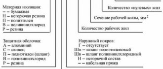
The essence of energized phasing is to determine the correspondence of the cable phase, which is energized from the switchgear at the opposite end of the cable, to the supposed phase of the same name of the switchgear buses where phasing is performed. For phasing 6 and 10 kV cable lines under voltage, 10 kV voltage indicators are used, complete with additional resistance, Figure No. 1. The integrity and coincidence of the phase designations of the connected cable cores must correspond.
Rice. No. 1 Phasing of live cable lines.
a – correspondence of cable and bus phases; b – different phases of buses and cables at the connection point of the latter; 1 – voltage indicator; 2 – resistance tube; 3 – wire; 4 – tire; 5 – end seal; 6 – cable; 7 – tire deflation connector.
Insulation resistance measurement.
Measurement of insulation resistance of high-voltage cables is carried out on a completely disconnected cable.
Before checking, it is necessary to check the reliability of the grounding of the cable funnels, armor and connect them to a portable grounding with special clamps (crocodiles). The second end of the cable remains free; the cores must be separated at a sufficient distance (approximately 150 - 200 mm).
If it is impossible to ensure the required distance between the cores and cable cores to grounded parts of the equipment, insulating caps or covers are put on the cores.
Before starting measurements, you must make sure that there is no
voltage, thoroughly clean the insulation from dust. Measurements should be made with the instrument needle in a stable position; To do this, you need to quickly but evenly rotate the generator handle (120 rpm) for 60 seconds. The insulation resistance is determined by the needle reading on the megohmmeter. To connect a megohmmeter to the device or line being tested, separate wires with a high insulation resistance (at least 100 mOhm) should be used.
A megohmmeter measures the resistance of the conductors one by one, and a portable grounding is installed on the conductors free from measurement. The circuit for measuring the insulation resistance of power cable lines is shown in Figure No. 2
Rice. No. 2 Scheme for measuring the insulation resistance of a power cable.
Measuring the insulation resistance of power and control cables with voltages up to 1000V is carried out in the same way, with measurements being made between every two wires (between phases, between phase conductors and zero, between phase conductors and a protective conductor, and between a neutral and protective conductor). When measuring, it is allowed to combine the neutral working and neutral protective conductors. For four-core cables, the insulation resistance of the neutral conductor is measured relative to grounded parts of electrical equipment.
Before the first or repeated measurements, the CL must be discharged by connecting all metal elements to each other and the ground for at least 2 minutes. The insulation resistance of cables up to 1 kV must be at least 0.5 MOhm. For power cables above 1 kV, the insulation resistance is not standardized. The measurement should be made before and after testing the cable with increased voltage.
Contents Previous § Next5.3. Standards and testing methods for new machines
5.3.1. Insulation resistance measurement
Insulation resistance characterizes its state at a given time and is not stable, since it depends on a number of factors, the main of which are the temperature and humidity of the insulation at the time of measurement.
GOST 183-74 does not define insulation resistance standards, since there are no absolute criteria for the minimum permissible insulation resistance. They can be established in standards for specific types of machines or in technical specifications with a mandatory indication of the temperature at which measurements should be carried out, and methods for recalculating instrument readings if measurements were carried out at a different winding temperature.
Measuring the insulation resistance of windings aims to establish the possibility of testing it with high voltage without an increased risk of damage to good, but high-moisture insulation.
Measurements are carried out with a megohmmeter, the rated voltage of which is selected depending on the rated voltage of the winding. For windings • with a rated voltage of up to 500 V (660) V, 500 V megohmmeters are used, for windings with voltages up to 3000 V - 1000 V megohmmeters, for windings with a rated voltage of 3000 V and more - 2500 V megohmmeters and higher.
The degree of insulation moisture is determined not only by the readings of the device at the time of reading, but also by the nature of the change in the megohmmeter reading during the measurement process, which is carried out within 1 minute. The instrument readings are recorded 15 s after the start of the measurement (J? 15) and at the end of the measurement - 60 s after the start (R60).
The ratio of these readings ka6 = ^6o/^is is called the absorption coefficient.
Its value is determined by the ratio of the polarization current to the leakage current through the dielectric - the winding insulation. With wet insulation, the absorption coefficient is close to 1. With dry insulation, R60
is 30-50% more than
R15,
and /sub 3* 1.3.
The megohmmeter also measures the insulation resistance of thermal converters embedded in machines and the wires connecting the thermal converters to the terminal board.
The resistance of this insulation is measured in relation to the frame and to the windings of the machine. It is not designed to operate at high voltages, so its resistance should be measured with a device with a rated voltage of no higher than 250 V.
In addition to the insulation resistance of the windings, when testing at the installation site of the machine, the insulation resistance of the bearings is also measured, which is installed to prevent the flow of bearing currents in machines with riser bearings.
Thus, the insulation resistance of different windings of the same machine, having different rated voltages, for example, the stator and rotor windings of a synchronous motor, must be measured with different megohmmeters with different rated voltages.
5.3.2. Measuring winding resistance at direct current
The resistance of the windings at direct current is an important machine parameter and should not differ significantly from the calculated values. However, the results of resistance measurements cannot be used to judge the correctness and quality of the work. This is primarily due to technological tolerances on the dimensions of the winding coils and tolerances on the resistance of the winding wire, which significantly affect the measurement results.
The possibility of a qualitative assessment is provided by comparing the results of measuring winding resistance with calculated (catalogue) data and with data obtained for other machines of the same type. It is often practiced to compare the results of resistance measurements of individual identical winding elements of one machine, for example, phases of a three-phase winding containing identical coils, or excitation coils of the same type. Since these elements are made from the same batch of winding wire and on the same templates, a discrepancy in the measurement results of more than 2 - 3% can serve as an indicator of a winding malfunction - incorrect connections in the circuit, the presence of closed turns in the coil and so on.
Methods for measuring resistance must ensure high accuracy (up to 0.4% during acceptance tests) and speed of measurements, which is especially important during acceptance tests.
To measure resistances greater than 1 ohm, ordinary (single) measuring bridges can be used, and for lower resistances, double bridges can be used, eliminating the influence of connecting conductors and contacts. A more universal measurement method is the voltmeter and ammeter method, which, with correctly selected instruments, circuit and measurement technique, ensures the necessary accuracy and speed of testing.
To measure the resistance of machine windings during acceptance tests during mass production, pointer or digital ohmmeters are used, which ensure fast measurements with a minimum number of necessary connections. However, this method has low accuracy, so it is not used for machines with low winding resistance.
5.3.3. Testing winding insulation for electrical strength
Testing the insulation of the windings relative to the housing and between the windings for electrical strength is carried out on all machines during acceptance and acceptance tests.
GOST 183-74 establishes that the insulation of a machine completely assembled at the manufacturer’s factory or its individual parts, as well as machines whose windings are fully or partially laid at the installation site of the machines, must withstand a test voltage of 50 Hz for 1 min.
The test voltage standards for acceptance and acceptance tests are given in Table. 5.2.
For turbogenerators, hydraulic generators and synchronous compensators, it is also mandatory to test the insulation after assembling the machine at the installation site. It is carried out with a test voltage equal to 80% of that specified in the table. 5.2 These tests are not carried out if the winding has been laid in whole or in part at the installation site of the machine and has been accordingly tested at 100% test voltage.
The insulation of each independent circuit of the machine is tested. At this time, all other windings are connected to the housing and grounded. In alternating current machines, independent circuits are all windings, the beginnings and ends of which have conclusions. In DC machines, the armature winding, the windings of additional poles connected to it and the compensation winding are usually taken as one circuit, and the various windings of the main poles are considered independent circuits.
If the winding test voltage is equal to or greater than 3000 V, it shall not be applied instantaneously. The test begins with no more than 50% of the full test voltage and increases to the full value gradually or in steps not exceeding each 5% of this value, so that the entire voltage rise time is at least 10 s. After maintaining the full test voltage for 1 minute, it must be reduced to half the value and only then turned off.
For machines with a power of up to 15 kW inclusive and a rated voltage of up to 660 V during their mass production on automated and mechanized technological equipment, electrical testing
Table 5.2. Test voltages of electrical machine windings
No.
| Electrical machine or parts thereof | Test voltage (rms value) | |
| 1 | Machines with a power of less than 1 kW (or 1 kV • A) with a rated voltage below 100 V, with the exception of those specified in paragraphs. 4 - 8 of this table | 500 IN plus 2 times rated voltage |
| 2 | Machines with a power of 1 kW (or 1 kVA) and above with a rated voltage below 100 V, with the exception of those specified in clause 4 | 1000 V plus 2 times rated voltage |
| 3 | Machines: a) with a power of up to 1000 kW (or 1000 kV-A), with the exception of those listed in paragraphs. 1.2 and 4-8 b) with a power of 1000 kW (or 1000 kV-A) and above, with the exception of those specified in paragraphs. 4 -8 per rated voltage: up to 3300 V over 3300 to 6600 V over 6600 to 17,000 V over 17000 V | 1000 V plus 2 times the rated voltage, but not less than 1500 V 1000 V plus 2 times the rated voltage 2.5 times the rated voltage 3000 V plus 2 times the rated voltage As agreed between manufacturers and the consumer |
| 4 | Excitation windings of DC machines with independent excitation | 1000 V plus 2 times the rated excitation voltage, but not less than 1500 V |
| 5 | Excitation windings of synchronous machines: a) generators, motors and compensators started by special starting motors b) machines intended for direct starting with an excitation winding closed to a resistance not exceeding 10 times the resistance of the field winding at direct current, or to its power source c) machines intended for starting with an excitation winding closed to a resistance whose value equal to 10 times the winding resistance or more, or with the field winding open, whether sectioned or not | 10 times the rated excitation voltage of the electric machine, but not less than 1500 V and not more than 3500 V 10 times the rated excitation voltage of the electric machine, but not less than 1500 V and not more than 3500 V 1000 V plus 2 times the maximum rms voltage that can be obtained under given starting conditions between the terminals of the field winding (between the terminals of any section), but not less than 1500 V (see note 3) |
| 6 | Secondary windings of asynchronous motors that are not continuously in a short-circuited state: a) for motors that allow back-switching braking b) for engines not intended for back-on braking | 1000 V plus four times the rated secondary voltage 1000 V plus two times the rated secondary voltage |
Continuation of the table. 5.2
| No. | Electrical machine or parts thereof | Test voltage (rms value) |
| 7 | Exciters (except as indicated below) Exciters for synchronous motors (including synchronized induction motors), if they are grounded or disconnected from the field windings during starting. Excitation windings of exciters with independent excitation | As for windings to which exciters are connected 1000 V plus twice the rated voltage of the exciter, but not less than 1500 V |
| 8 | Grouped electrical machines and apparatus | If a group consisting of several new, newly installed and connected together electrical machines and apparatus, of which each machine and each apparatus has been tested for electrical strength, is subjected to testing, then the test voltage should not exceed 85% of the test voltage of that machine (or apparatus) , which (which) has the lowest voltage |
Notes: 1. Test voltage for machines with different insulation levels is determined by agreement between the manufacturer and the consumer.
2. For two-phase windings having a common terminal, the rated voltage, by which the test voltage is determined, should be taken equal to 1.4 times the voltage of an individual phase.
3. The voltage obtained under starting conditions between the terminals of the field windings or between the terminals of sections can be measured at a reduced supply voltage. The voltage measured in this way should be multiplied by the ratio of the voltage obtained under starting conditions to the reduced supply voltage.
4. For the windings of one or more machines that are electrically connected, the voltage considered is the maximum voltage with respect to ground.
Testing of insulation strength can be carried out by applying a test voltage for 1 s. In this case, it should be increased by 20% compared to that indicated in the table. 5.2. Carrying out acceptance tests of such machines at most factories is automated.
5.3.4. Testing the interturn insulation of windings
GOST 183-74 establishes that the turn-to-turn insulation of electrical machine windings must be tested with a voltage exceeding the rated voltage by 30% for 3 minutes. An increase in the interturn voltage is achieved by a corresponding increase in the voltage at the winding terminals when the machine is no-load.
In asynchronous machines, the no-load current of which, when the voltage increases, is 1.3 times higher than the rated one, for example, in motors with high saturation
magnetic core steel, the test duration can be reduced to 1 min. The test can also be carried out when the stator is supplied with a high-frequency current. The current frequency can be increased by no more than 15% compared to the nominal one. Turn-to-turn insulation of the stator and rotor windings of asynchronous motors with phase-wound rotors is tested simultaneously with a stationary (locked) and open rotor.
Turn-to-turn insulation of synchronous machines (except for turbogenerators and hydrogenerators) is also tested at a voltage that is 30% higher than the nominal voltage. In machines whose voltage in generator mode at the rated excitation current exceeds the rated one by more than 30%, the test is carried out at an open circuit voltage corresponding to the rated excitation current.
Interturn insulation of hydraulic windings
generators are tested with a voltage of 50%, and turbogenerators - 30% higher than the nominal voltage for 5 minutes. If the specified increase in the voltage of the generators cannot be achieved by increasing their excitation current to the rated one, then it is allowed to simultaneously increase the rotation speed of the machines, but not more than 15% above the rated one.
The interturn insulation of the windings of inductors powered by direct current is not tested in the assembled machine. Its tests are carried out before assembly, during operational control.
The test voltages of the turn-to-turn insulation of the armature windings of DC machines do not depend on the rated voltage and are determined based on the average voltage between adjacent collector plates, which should not exceed 24 V. For electric machine exciters designed for focusing excitation, at which the voltage can exceed 130% nominal, the test is carried out at the maximum boost voltage, but the test time is reduced to 1 min.
In recent years, devices based on the principle of using high frequency or pulse voltage have become increasingly widespread for testing the electrical strength of turn-to-turn insulation. GOST allows the use of these devices for testing the interturn insulation of coil windings of machines with a rated voltage of not more than 660 V.
5.3.5. Momentary overcurrent test
Acceptance test programs for all types of machines contain a short-term overcurrent test. The multiplicity of the overload current in relation to the rated one and the test time at a given current are determined by the type of machine.
Collector machines of direct and alternating current are tested for 1 minute for a short-term overload of current, 50% higher than the rated one, and exciters - with a limiting excitation ratio of more than 1.6 - 2 times the rated excitation current of the excited machine.
Brushless AC machines with a power of 0.55 kW and above, including turbo and hydrogen generators with indirect winding cooling, are tested for
current overload 50% higher than the rated current for 2 minutes, and with direct cooling of the windings - for 1 minute.
Machines whose rated mode is intermittent or intermittent with a period of operation less than 1 minute are not tested for short-term overcurrent.
The standards and duration of short-term overcurrent tests for low-power and special-design machines are established in standards or technical specifications for specific types of machines. They may differ significantly from those given above.
5.3.6. High speed tests
Tests at increased speed are carried out for all types of machines. Their purpose is to check the mechanical strength of rotating parts. All electrical machines, except for commutator machines and a number of special-design machines, must withstand, without damage or residual deformation, an increase in rotation speed of 20% above the rated speed for 2 minutes, and motors with frequency control - 20% above the highest, motors with sequential excitation of constant and alternating current - 20% above the highest indicated on the nameplate, but not less than 50% above the rated value. The same standards apply to motors with mixed excitation, if they provide for regulation of the rotation speed within a range of no more than 35% above the nominal.
Special-purpose machines, including hydraulic generators, metallurgical and crane generators, rolling stock engines, etc., are tested at increased speed in accordance with the requirements of standards or specifications.
When conducting tests at increased speed, for the safety of personnel, the use of manual tachometers is prohibited. Frequency measurements must be remote. To prevent accidental exceeding of the specified test speed, the increase in speed must be smooth.
5.3.7. Heat test
Electrical machine standards do not evaluate the thermal state of the machine
by the temperature of its parts, and by the excess of their temperature above the temperature of the cooling medium, which for normal operating conditions is taken equal to 40°C. An exception is the assessment of heating of bearings and thrust bearings, for the normal operation of which a certain viscosity of lubricants is important, determined by their temperature, which depends relatively little on the ambient temperature.
To measure the heating of parts of electrical machines, the standards provide three methods: the resistance method, the thermometer method and the method of embedded thermal converters (thermal indicators).
Resistance method
is based on changes in the direct current resistance of the winding conductors depending on their temperature. It is used to determine the temperature of insulated windings and allows you to determine their average temperature or the average temperature of a separate part of the winding (parallel branch, if it has separate terminals or winding phases). Uneven heating of sections or individual points of the winding cannot be determined by this method.
To determine the temperature of the winding, this method measures its resistance to direct current in a practically cold state of the machine Rx
or at a known winding temperature 9X and in a heated state
RT.
The temperature in the heated state Eg is determined by the temperature coefficient of resistance a known for the winding material, referred to a certain conventional temperature 9 at which the winding resistance is equal to
R.
When testing electrical machines for winding copper, use the temperature coefficient value referred to the temperature & = = 15 ° C equal to a = 0.004 1/°C. Then the average temperature of the winding, based on measurements of its resistance in hot and cold states, can be calculated using the formula
the surface of the stator magnetic core or winding end parts, but not inside these parts.
To carry out measurements using this method, both expansion thermometers (mercury or alcohol, if the measuring points are located in an alternating magnetic field) and other types of temperature meters or thermal converters applied to accessible points on the surface of machine parts are used.
Embedded thermal converter method
provides for temperature measurement using thermoelectric converters, thermocouples or thermistors of which are placed inside parts of the machine at points where the greatest increase in temperature is expected, for example, at the bottom of the grooves for the winding or in the grooves between the sides of the coils, etc. Their lead ends are brought out to the measuring circuits .
The readings of the instruments included in the thermal converter circuits are used both for thermal testing of machines and for monitoring the thermal state of the machine during the entire period of its operation.
When conducting detailed thermal tests of electrical machines or during research tests, additional elements of thermal converters are installed in the machines, the number and installation location of which is determined in such a way as to obtain a complete picture of the temperature field of the machine.
Other methods are also used to measure the temperature of machine parts. To measure temperature in a closed volume, for example, the temperature of oil in bearings, pressure thermometers can be used, the readings of which are based on changes in pressure in the surrounding space. To non-contactly measure the temperature of the surface of rotating parts of a machine, for example the surface of a commutator, so-called “thermal imagers” can be used, the readings of which vary depending on the intensity of the infrared radiation of the heated surface.
Heat sensitive paint method
is based on the property of some paints to change their color at a certain temperature and retain the changed color after cooling. This makes it possible, using a set of several paints designed for specific temperatures, to relatively easily determine the heating limits of rotating parts that are inaccessible for observation when the machine is operating. However, this method gives
and the excess of the winding temperature over the temperature of the cooling medium
D9G = Eg - Eo,
where Eo is the temperature of the cooling medium. Thermometer method
is based on measuring the temperature of individual points of accessible surfaces of parts of an electric machine, for example the temperature of points of external
low measurement accuracy due to the limited range of heat-sensitive paints.
Methods for conducting heating tests and determining the steady-state temperature of machine parts under nominal operating conditions are defined in GOST 25000-81 (see Table 5.1).
5.3.8. Determination of efficiency
The efficiency of an electric machine is the ratio of the active power P2 supplied by the machine to the active power P1 supplied to the machine;
Efficiency is usually expressed as a percentage:
P = 100 Р2/Р„ or in fractions of a unit:
L = P2/P1. (5.1)
The electrical power supplied to the engine and the electrical power supplied to the network by the generator are measured directly using wattmeters. Measuring the mechanical power supplied by the engine and supplied to the generator is difficult and requires special devices. This complicates the determination of the efficiency of electric machines.
The input and output power of an electrical machine differ by the amount of losses in it that arise in the process of mutual conversion of electrical and mechanical energies P2 = Ru
— £Р. Based on this, the expression for efficiency can be written in another form:
for engines
ti = 1-£P/Pi; (5.2a)
for generators
L = 1-1P/(P2 + XP). (5.26)
According to the two forms of notation (5.1) and (5.2), there are two groups of methods for determining efficiency: methods of direct determination, i.e. direct and simultaneous measurement of P and P2 of the machine under test, and methods of indirect determination of efficiency, in which only losses in the machine are measured. The amount of losses £ P refers to the electrical power consumed by the engine or supplied to the network by the generator.
Methods for directly determining
efficiency.
The standards provide three methods for directly determining efficiency.
Electrical power measurement method
used to determine the efficiency of converter units consisting of an engine and one or more generators, produced as a set. Electrical active powers are measured at the motor input and at the generator (or generators) output. The difference in measured powers is equal to the total losses in the unit, the ratio of powers is the efficiency of the unit or, which is the same, the product of the efficiency of all machines included in the unit.
Braking method
used mainly to determine the efficiency of engines. Braking is carried out by a mechanical or other brake with a torque meter. The mechanical power delivered by the engine (motor shaft power) is defined as the product of torque and rotational speed. The active electrical power consumed by the engine from the network is measured with a wattmeter.
Load method
can be used for both engines and generators.
A calibrated generator is used as the load of the engine under test, supplying energy to a special load device or to the network. In the experiments, the electrical active power supplied to the engine, P{D,
and the electrical active power supplied by the calibrated generator,
P-^ are measured.
The efficiency of the tested engine t|d is determined taking into account the efficiency of the calibrated generator g|t:
Ld = P2t/(Lt^1d)-
To determine the generator efficiency, a calibrated engine is used. The efficiency of the generator being tested d)r is determined by the ratio of the powers delivered by the generator P-^
and supplied to the calibrated PiT engine, taking into account its efficiency:
Lg = P2g/(P1t^1t)-
Methods for directly determining efficiency are inferior to indirect methods both in measurement complexity and accuracy. This is due to several reasons, the main ones being:
the difficulty of creating and measuring the braking torque on the shaft of the motor being tested or the torque on the shaft of the generator being tested. When testing high-power machines, this task becomes insoluble in the conditions of a conventional enterprise test station;
the need to ensure, when carrying out measurements, the same thermal state of the machine under test as in the operating mode for which the efficiency is determined. Failure to comply with this condition leads to a large error in determining the efficiency due to changes in losses in the machine under test, which depend on temperature.
In this regard, the standards allow the use of methods for directly determining efficiency only for machines with guaranteed efficiency values of less than 85%. For machines with high efficiency values, its determination should be made by indirect methods.
Indirect methods for determining efficiency.
Of the group of methods for indirectly determining efficiency, the main one is the method of separate determination of losses. Each type of loss is determined or calculated based on data from relevant experiments conducted in certain modes.
Basic and additional losses in steel
are determined from no-load experience for a voltage corresponding to the operating mode, and for DC machines with a rated voltage of less than 100 V - taking into account the voltage drop on all elements of the series armature circuit. In this case, all resistances of the elements of the series circuit are reduced to the design temperature.
Mechanical losses
including friction losses in supports, sliding contacts and on all surfaces washed by cooled media, are also determined by the method of separating losses from idling experience.
Electrical losses in operating and field windings
are determined by the operating current in these windings and their resistances reduced to the design temperature.
Electrical losses in sliding contacts
are calculated as the product of the currents through the contacts and the transient voltage drop under the brushes, which is considered independent of the current.
Additional load losses are taken into account as a percentage of power input for motors and power output for generators at their rated load. Additional losses for compensated DC machines, synchronous machines with a power of up to 100 kV • A and asynchronous brushless machines are taken in calculations equal to 0.5% of the rated power; for uncompensated DC machines - 1%; for collector
AC machines - also 1%, unless other values are provided for them by the relevant documents. When the power differs from the rated one, the values of additional losses are recalculated in proportion to the square of the operating circuit current.
For synchronous machines with a power of more than 100 kV-A, when determining efficiency, additional losses are not calculated. They are obtained experimentally in addition to the main electrical losses in the stator winding.
For DC motors with wide speed control, the calculated additional losses are increased by multiplying by the following factors, depending on the speed for which the efficiency is calculated:
Ratio of rotation speed to nominal 1.5 2.0 3.0 4.0
Coefficient of increase in additional losses 1.4 1.7 2.5 3.2
When testing synchronous compensators, the amount of losses is determined and referred to the total power of the machine, since the concept of efficiency does not make sense for them.
Methods for determining efficiency and individual types of losses are described in more detail in GOST 25492-83 (see Table 5.1).
5.3.9. Vibration and noise measurements
USSR standards stipulate the measurement of vibration and noise of electrical machines as mandatory only in acceptance tests. However, issues of reducing vibration and noise have recently received increasing attention. Increasing requirements for the vibroacoustic characteristics of electric machines are reflected in the standards and specifications for specific types of machines of new series. Considering that these characteristics have less stability compared to other technical data of machines, as well as the strict requirements of standards and specifications for their acceptable level, many enterprises measure the noise and vibration of each machine produced. Thus, these tests for a large number of types of machines turn into acceptance testing programs.
To measure vibroacoustic characteristics, special equipment is used, which allows not only to measure the noise and vibration levels of the machines under test, but also to obtain data
to analyze the reasons for the deterioration of these characteristics.
Measurements of noise and vibration of electrical machines are carried out in accordance with GOST 11929-81 and GOST 20815-71 (see Table 5.1).
5.3.10. Characteristics and parameters of electrical machines
Test programs for different types of machines in addition to those discussed in paragraphs. 5.3.1 - 5.3.9 contain a number of points related to determining the characteristics of engines and generators, individual machine parameters, characteristic points of mechanical characteristics, etc. The requirements for machines when testing under these program points are set out in GOST 183- 74 in relation to each type of machine and in the standards and specifications for specific types of machines.
Methods for carrying out the relevant tests are defined in the test method standards (see Table 5.1).
The terms and definitions of concepts used in programs and in the description of test methods are established by GOST 17154-71.
Contents Previous § Next
Test with increased voltage of rectified current.
Testing the insulation of cable lines with increased voltage of rectified current is carried out in order to identify local concentrated defects that are not detected when measured with a megohmmeter, by bringing them to breakdown during the test. Such a test with increased voltage of rectified current is carried out from a special installation such as: AID-70, SKAT-70, etc.
The voltage from the installation is applied in turn to each phase of the cable, while grounding the other two phases and the cable sheath (similar to measuring insulation with a megohmmeter). The circuit for testing the cable with increased voltage of rectified current is shown in Figure No. 3.
Rice. No. 3 Testing the cable with increased rectified voltage.
Insulation of single-core cables without metal screen (sheath, armor),
laid in air are not tested. The insulation of single-core cables with a metal screen (sheath, armor) is tested between the core and the screen. The insulation of multi-core cables without a metal screen (sheath, armor) is tested between each core and the remaining cores connected to each other and the ground.
The insulation of multi-core cables with a common metal screen (sheath, armor) is tested between each core and the remaining cores connected to each other and the screen (sheath, armor). For all of the above types of tests, metal screens (shells, armor) must be grounded. Plastic sheaths (hoses) of cables laid in the ground are tested between screens (sheaths) disconnected from the ground and the ground. Plastic sheaths (hoses) of cables laid in air are not tested. The test voltage value is taken in accordance with table No. 2
Test voltage kV, for power cables.
Table No. 2
| Type of test | Test voltage (kV) for cable lines | ||
| Paper insulated cables | |||
| Up to 1kV | 6kV | 10kV | |
| P | 6 | 36 | 60 |
| TO | 2,5 | 36 | 60 |
| M | — | 36 | 60 |
| Type of test | Plastic insulated cables | ||
| Up to 1kV* | 6kV | 10kV | |
| P | 3,5 | 36 | 60 |
| TO | — | 36 | 60 |
| M | — | 36 | 60 |
| Type of test | Rubber insulated cables | ||
| Up to 3kV | 6kV | 10kV | |
| P | 6 | 12 | 20 |
| TO | 6 | 12 | 20 |
| M | 6** | 12** | 20** |
* - high voltage testing of single-core cables with plastic insulation without armor (screens) laid in the air is not carried out.
** - after repairs not related to cable reinstallation, the insulation is checked with a megohmmeter for a voltage of 2500V, and testing with increased rectified voltage is not performed.
For cables for voltages up to 10 kV with paper and plastic insulation, the duration of application of the full test voltage during acceptance tests is 10 minutes, in operation 5 minutes. For cables with rubber insulation for voltage 6-10 kV, the duration of application of the full test voltage is 5 minutes.
Permissible leakage currents depending on the test voltage and permissible values of the asymmetry coefficient when measuring leakage current are given in Table No. 3. The absolute value of the leakage current is not a rejection indicator. Cable lines with satisfactory insulation must have stable leakage current values. During testing, the leakage current should decrease. If there is no decrease in the leakage current, or if it increases or becomes unstable, the test is carried out until the defect is identified, but not more than 15 minutes.
Insulation breakdown test: methodology
Nevertheless, high-voltage breakdown testing of insulation is still the most effective and most commonly used method, which is carried out according to a certain methodology.
The testing site must be securely fenced. After the test circuit is assembled, it is checked to ensure that it is connected correctly. The increase in voltage, as well as the time required for this increase, are strictly regulated by standards and GOSTs. Deviation from the norms specified therein is prohibited. Upon completion of the resistance test, the high-voltage installation is turned off, its voltage indicator is transferred to the zero position, and the equipment on which the test work was carried out is grounded to release the residual voltage for a period of 3 to 5 minutes. The test is considered passed only when no insulation breakdown is detected.
Example of a technical report
Back
Forward
Below you can use the online calculator to calculate the cost of electrical laboratory services.
Permissible leakage currents and asymmetry coefficient values for power cables.
Table No. 3
| Cable voltage (kV) | Test voltage (kV) | Permissible values of leakage currents (mA) | Acceptable values of coefficient. asymmetry |
| 6 | 36 | 0,2 | 8 |
| 10 | 45 | 0,3 | 8 |
| 50 | 0,5 | 8 | |
| 60 | 0,5 | 8 |
It is allowed to the technical manager of the enterprise during operation (M), based on local conditions, as an exception, to reduce the test voltage level for cable lines with a voltage of 6-10 kV to 0.4 Un.
Frequency of testing during operation.
Cables with voltage 2-35kV:
a) once a year - for cable lines during the first 2 years after commissioning, and thereafter:
- Once every 2 years - for cable lines for which during the first 2 years there were no emergency breakdowns or breakdowns during preventive tests, 1 time per year for cable lines on the routes of which construction and repair work was carried out and on which emergency breakdowns systematically occur isolation;
- 1 time every 3 years - for cable lines in closed areas (substations, factories, etc.); during major repairs of equipment for cable lines connected to units, 6-10 kV cable jumpers between busbars and transformers in TP and RP ;
b) It is permissible not to carry out the test:
- For cable lines up to 100 meters long, which are outputs from switchgear and transformer substations to overhead lines and consisting of two parallel cables;
- For cable lines with a service life of more than 15 years, on which the specific number of failures due to electrical breakdown is 30 or more failures per 100 kilometers per year;
- For cable lines subject to reconstruction or decommissioning in the next 5 years;
c) It is allowed by order of the technical manager of the enterprise to establish
other values of test frequency and test voltages:
- For supply cable lines for voltage 6-10 kV with a service life of more than 15 years with a number of connecting couplings of more than 10 per 1 kilometer of length;
- For supply cable lines with a voltage of 6-10 kV with a service life of more than 15 years, on which only KVV and KVB types of terminations and locally manufactured couplings are installed, with a test voltage value of at least 4 Un and a frequency of at least 1 time in 5 years.
- For cable lines with a voltage of 20-35 kV, during the first 15 years the test voltage should be 5 Un, and then 4 Un.
6.3.8 Cables for voltage 3-10 kV with rubber insulation:
- in stationary installations – once a year;
- in seasonal settings - before the onset of the season;
- after a major overhaul of the unit to which the cable is connected.
Electrical Insulation Testing
To operate safely, all electrical installations and equipment must have an insulation resistance that meets certain specifications. Whether in connection cables, isolation and protection equipment, or electric motors and generators, electrical conductors are insulated using materials with high electrical resistance that limit, as much as possible, the electrical current outside the conductors.
Due to impacts on equipment, the quality of these insulating materials varies over time. Such changes reduce the electrical resistance of insulating materials, which increases leakage current, which in turn leads to serious consequences, both in terms of safety (for people and property) and in terms of costs of production shutdowns.
Regular insulation testing carried out on plants and equipment, in addition to measurements taken on new and refurbished equipment during commissioning, helps avoid such incidents through preventive maintenance. These tests make it possible to detect aging and premature deterioration of insulation properties before they reach levels that could lead to the incidents described above.
At this point, it is useful to clarify the difference between two types of measurements that are often confused - dielectric strength testing and insulation resistance testing.
The dielectric strength test, also called the flashover test, determines the ability of an insulation to withstand a medium-duration voltage surge without sparking. In fact, such a voltage surge can be caused by lightning or induction as a result of a faulty power line. The main purpose of this test is to ensure compliance with building codes regarding creepage distances and clearances. This test is often performed using AC voltage, but the test also uses DC voltage. This type of measurement requires the use of a high voltage tester. The result is a voltage value, usually expressed in kilovolts (kV). Electrical strength testing can be devastating if it fails, depending on the testing levels and the energy capabilities of the instrument. Therefore, this method is used for routine testing on new or refurbished equipment.
Under normal test conditions, insulation resistance measurement is a non-destructive test. This measurement is performed using a lower DC voltage than the dielectric strength test and gives a result expressed in kOhms, MOhms, GOhms or TOhms. The resistance value indicates the quality of the insulation between two conductors. Since this test is non-destructive, it is particularly suitable for monitoring the aging of the insulation of operating electrical equipment or installations. An insulation tester, also called a megger, is used for this measurement.
Insulation and reasons for its failure
Since measuring insulation using a megger is part of a broader preventive maintenance policy, it is important to understand the reasons why insulation performance may deteriorate. Only this will allow you to take the right steps to eliminate them.
The causes of insulation failure can be divided into five groups. However, it must be borne in mind that in the absence of any corrective measures, various causes will overlap each other, leading to insulation breakdown and equipment damage.
Electrical loads
Basically, electrical loads are associated with the deviation of the operating voltage from the nominal value, and both overvoltage and undervoltage have an impact on the insulation.
Mechanical loads
Frequent sequential starts and stops of equipment can cause mechanical stress. This also includes problems with balancing rotating machines and any direct stress on cables and installations in general.
Chemical influences
The presence of chemicals, oils, aggressive fumes and dust generally negatively affects the performance of insulating materials.
Stresses associated with temperature fluctuations
In combination with the mechanical stresses caused by successive starts and stops of equipment, the properties of insulating materials are also affected by the stresses generated by expansion and contraction. Working at extreme temperatures also causes aging of materials.
Environmental pollution
Mold and foreign particles in warm, humid environments also contribute to the deterioration of the insulation properties of installations and equipment.
The table below shows the relative frequency of various causes of motor failure.
External pollution
In addition to sudden insulation failures due to extreme events such as floods, factors that reduce the insulation effectiveness of an operating installation combine, sometimes reinforcing each other. Ultimately, in the long term, without constant monitoring, this will lead to situations that become critical from the point of view of human safety and normal operation. Regular testing of the insulation of installations or electrical machines is therefore a useful way to monitor the condition of the insulation, allowing necessary action to be taken before damage occurs.
Measuring current distribution in single-core cables
On the power cable, currents flowing both in the conductors and in the metal sheaths and armor are measured. Measurements are made using current clamps.
Depending on the sheath material, armor and position of the cable in space, the currents in them can reach 100% relative to the core current and greatly affect the heating of the cables. Simultaneously with measuring currents at loads close to the rated load, the temperature of the outer covers of the cables must be measured, from which the temperature of the core can be calculated. This temperature should be measured at the hottest point of the cable line and should not exceed the permissible temperature for a given measurement location. If the current distribution is uneven by more than 10%, when individual cables limit the throughput of the entire group of cables, measures must be taken to equalize the currents across phases.
Principle of insulation testing and factors affecting it
Insulation resistance measurement is based on Ohm's law. By applying a known DC voltage at a level lower than the dielectric test voltage and then measuring the current value, it is very easy to determine the resistance value. In principle, the value of the insulation resistance is very large, but not infinite, therefore, when measuring a small flowing current, the megohmmeter indicates the value of the insulation resistance in kOhm, MOhm, GOhm and even in TOhm (on some models). This resistance characterizes the quality of the insulation between two conductors and can indicate the risk of leakage current.
The value of the insulation resistance, and therefore the amount of current that flows when DC voltage is applied to the circuit under test, is influenced by a number of factors. Such factors include, for example, temperature or humidity, which can significantly affect the measurement results. First, let's analyze the nature of the currents flowing during an insulation measurement, using the hypothesis that these factors do not affect the measurement being made.
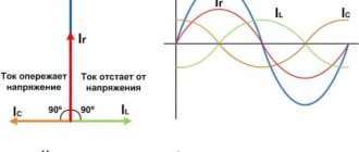
The total current flowing in the insulating material is the sum of three components
Capacitance: To charge the capacitance of the insulation under test, a capacitance charging current is required. This is a transient current that starts at a relatively high value and drops exponentially to a value close to zero as the circuit under test becomes electrically charged. After a few seconds or tenths of a second, this current becomes insignificant compared to the measured current.
Absorption: Absorption current corresponding to the additional energy required to reorient the molecules of an insulating material under the influence of an applied electric field. This current drops much more slowly than the capacitance charging current; sometimes it takes several minutes to reach a value close to zero.
Leakage Current: Leakage current or conduction current. This current characterizes the quality of the insulation and does not change over time.
The graph below shows these three currents as a function of time. The time scale is arbitrary and may vary depending on the insulation being tested.
To ensure proper test results on very large motors or very long cables, minimizing capacitive and absorption currents can take 30 to 40 minutes.
When a constant voltage is applied to a circuit, the total current flowing in the insulator under test varies as a function of time. This implies a significant change in insulation resistance.
Before looking in detail at the various measurement methods, it would be useful to take another look at the factors that influence insulation resistance measurement.
Effect of temperature
Temperature causes a quasi-exponential change in the insulation resistance value. In the context of a preventive maintenance program, measurements should be made under uniform temperature conditions or, if this is not possible, should be corrected relative to a reference temperature. For example, a 10°C increase in temperature reduces the insulation resistance by approximately half, while a 10°C decrease in temperature doubles the insulation resistance value.
The level of humidity affects the insulation according to the degree of contamination of its surface. Never measure insulation resistance when the temperature is below the dew point.
Correction of insulation resistance depending on temperature (source IEEE-43-2000)