There may be tens or even hundreds of kilometers between electricity generators and consumers. To minimize losses during transportation, a special technology is used, the essence of which is to increase the voltage, transmit it through power lines and lower it to the level of the consumer network. The last stage of transformation is carried out at substations equipped with power transformers (hereinafter referred to as ST). In this publication we will tell you what these devices are, their main design elements and features.
What is a power transformer and its purpose
This is a device that converts the amplitude of alternating voltage, leaving its frequency unchanged. The operation of such a device is based on the principle of electromagnetic induction. We will not be distracted by its description; all detailed information can be found on the pages of our website.
The main scope of application of ST is related to the transmission and distribution of electricity, this is presented in a simplified manner in the figure below.
Electricity transmission scheme
As can be seen from the figure, several CTs can be installed in the circuit between the generator and the consumer. The first increases the voltage to 110 kV (the higher it is, the lower the losses during long-distance transmission) and supplies it to the power line. At the output of the line, a second CT is installed at the regional substation, from where transmission is carried out via an underground cable to the transformer point, from where the end consumers are powered.
Transformer point
Scope of application
Such devices are often installed on electronic equipment units and perform different functions. In recent years, several new enterprises have mastered the technology for their production. The adaptability of the device to work with different consumers has increased, since it has become possible to produce according to the specified technical requirements of the customer. Nothing like this had happened before.
Equipment designers used standard diagrams and components from reference books. The choice of products was large, but did not cover the full list of needs. Therefore, many developers installed units with excess power reserves. Today, many enterprises produce components with characteristics that suit the customer.
Accepted classifications
Considering the considerable weight and size of the CT, in order to simplify a number of works related to maintenance, transportation and planning, these devices are usually divided into dimensional groups. Below is a table showing the correspondence.
CT Dimensions Table:
| Dimensional group | Minimum power (kV*A) | Maximum power (kV*A) | UMAX (kV) |
| I | 10,0 | 100,0 | 35,0 |
| II | 160,0 | 630,0 | |
| III | 1000,0 | 6300,0 | |
| IV-1 | 10000,0 | 40000,0 | |
| IV-2 | 6300,0 | 63000,0 | 110,0 |
| V-1 | 100000,0 | 250000,0 | |
| V-2 | 10000,0 | 250000,0 | 220,0-330,0 |
| VI-1 | 250000.0 or more | from 330.0 and more | |
| VI-2 | no power or voltage restrictions | ||
Power transformer of the 5th size group TRDTsN-63000/220, weight about 130 tons
In addition to the overall distribution, ST is also classified according to the following indicators:
- number of phases (as a rule, substations are equipped with three-phase converters);
- number of windings (two or three);
- functional purpose (decreasing or increasing amplitude);
- execution (installation indoors or outdoors);
- heat removal system (air or oil).
Classification of transformers by circuit parameters
Among the many features of transformers, one can highlight parameters that characterize their use and purpose in the electrical circuit or the circuit of the transformer itself. Therefore, we will highlight several factors characterizing transformers: circuit purpose and transformer circuit.
1. Classification of transformers according to circuit purpose allows us to determine the functions that it performs in a specific circuit, and accordingly three groups can be distinguished:
— power transformers are designed to supply alternating current to various parts and components of equipment, therefore power transformers are sometimes called TP power transformers. This group is the most common and accounts for up to 70% of all transformers. They are widely used to power a wide variety of loads: electric motors, household appliances, various amplifiers, rectifiers, lighting and heating devices.
Power transformer TP-60.
— matching transformers are used to match the input and output impedances of various components of an electronic circuit and are widely used in radio receiving, radio transmitting and amplification equipment. They can be divided into several types depending on their location in the circuit: input, intermediate and output.
Matching transformer RCF TD507.
— pulse transformers are used to transmit voltage and current pulses between individual sections of an electrical circuit. A special feature of these transformers is that they allow pulses of varying durations to pass through them - from microseconds to nanoseconds. The pulse shape is most often rectangular, but any other is possible: triangular, sawtooth, bell-shaped and others.
Pulse transformer.
2. In addition to their circuit purpose, transformers are classified according to the transformer circuit and allow us to distinguish the following types:
- a single-winding transformer called an autotransformer . It is characterized by the fact that there is a magnetic and electrical connection between the primary (input) and secondary (output) windings. The primary and secondary windings are determined by taps from the common winding.
Autotransformer designation.
— a two-winding transformer , unlike a single-winding one, has two electrically unconnected windings. This type of transformer is basic and, in theoretical analysis, is basic and the electrical parameters of the primary winding are connected by unambiguous relationships with the electrical parameters of the secondary winding.
Designation of a two-winding transformer.
- multi-winding transformers have several electrically unconnected secondary windings, the number of which reaches ten, but most often four or five. In this type of transformer, the primary winding current is determined by many relationships with the secondary winding current. This type of transformer is the most common.
Designation of a multi-winding transformer (two secondary windings).
Design features
Despite the variety of types of CT, their design invariably includes the following mandatory elements:
- outputs of high and low voltage coils (HV and LV), they are usually called power inputs;
- heat removal system;
- devices that allow you to regulate the operating voltage;
- additional equipment for monitoring the operation and maintenance of the device.
The figure below shows a typical CT design with an oil heat removal system.
Oil Cooled Power Transformer Design
Designations:
- A – expansion tank, serves to level the oil level when its volume changes due to temperature fluctuations.
- B – power input for HV.
- C - input for NN.
- D – operating voltage switch.
- E – radiator, consists of pipes through which oil circulates.
- F – housing, also plays the role of an oil tank.
- G and H – HV and LV coils.
- I – magnetic conductive core.
Now we will consider in detail the purpose of the main structural elements.
Purpose of power inputs
This design element is necessary to connect power and load to the CT. Their location can be either internal (closed terminal blocks) or external. Please note that the first arrangement option is used only in STs with an air heat removal system.
It is necessary to have insulation between the input and the housing; it can be oil barrier, SF6, capacitor-through, or made of materials that do not conduct electricity (porcelain, polymers, etc.).
Rice. 4. Porcelain insulators on the power transformer inputs
Types and technical characteristics
Power electrical devices of rod and armor type are manufactured. The latter is the most affordable and weighs less. Most transformers are manufactured according to this principle. Rod-type products with a paired coil are also often used. They heat up less, and copper is saved during manufacturing due to shortened turns. The current density in such windings increases significantly. Rod devices with one coil consume more materials, but are much easier to manufacture.
Heat removal system
During the conversion of electricity, part of the losses is released in the form of heat, so a heat removal system is invariably present in any PT. Powerful devices are equipped for this purpose with a special dual-circuit system, in which the oil is cooled in the following ways:
- By means of radiators (see E in Fig. 4), which provide heat removal to the secondary or external environment.
- Tank housing with a corrugated surface (used in low-power devices).
- Installation of ventilation equipment. This solution allows you to increase productivity by a quarter.
Fans of the forced cooling system ST - Additional water cooling systems. This is one of the simplest and most effective ways to remove heat.
- The use of special pumps that circulate oil in the heat removal system.
Operating voltage control devices
In some cases, it becomes necessary to increase or decrease the CT load voltage; for this purpose, most designs provide a special switch. Essentially, it changes the transformation ratio by switching to more or less turns in the coils.
As a rule, such manipulations are performed when the load is removed, but there are devices that allow you to change the CT without disconnecting consumers.
Types of additional equipment
To ensure stable operation and maintenance of CTs, their design may include the following devices, called attachments or additional equipment:
- The gas pressure switch is a protective system. If the CT goes into abnormal operation mode, then as a result of large heat release, oil decomposition occurs. This process is accompanied by the release of gas. When it forms quickly, a protection is triggered, disconnecting the device from power and load. If the gas formation process is slow, an alert is activated.
- Thermal indicators show the heating of the oil in various components of the heat removal system.
Oil temperature indicator - Desiccants. They are used in non-sealed oil heat removal systems and prevent the formation of water condensation.
- Oil regeneration systems.
- Pressure sensors, if it exceeds a certain threshold, the reset device is automatically turned on to normalize.
- Oil fill level sensor in the heat removal system.
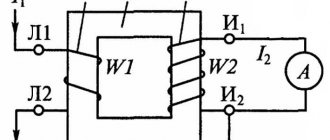
Transformer operation testing technology
The quality of the device is checked using a multimeter. Turn-to-turn short circuit is a common fault. It is also necessary to monitor changes in the external characteristics and smell of the product. The varnish coating serves as an insulating material during the walk, after damage to which the temperature in the problem area rises due to the persistence of resistance. Serviceable products do not have blackening, drips or swelling.
The paper should not be charred and there should be no burning smell. The winding resistance can be determined from a reference book if the type of device is known. The data obtained after measurement using a multimeter is compared with the information in the reference book. Coils are considered faulty if the difference between the indicators exceeds 50%. If the resistance of the windings is unknown, you need to use the number of turns, cross-section and material from which the wire is made when making calculations.
Accepted markings
The alphanumeric designations of ST are made in accordance with the figure below.
Power transformer marking
Designations:
- The type of device is indicated. Options “A”, “L”, “E” or no symbol are possible, which corresponds to an autotransformer, linear or furnace device. The absence of a symbol indicates a regular ST.
- “O” or “T” corresponds to a single-phase or three-phase device.
- Heat removal option used (for oil systems), possible options:
- M – compulsory systems are not used.
- D – forced airflow is performed.
- DC – forced airflow with non-directional circulation is performed.
- NC – water-oil cooling with directed circulation.
- C – water-oil cooling with non-directional circulation.
- Indication of power in kV*A.
- Permissible HV level (kV).
- Execution option (external or internal placement, special climatic conditions, etc.)
Design of coils of low-power transformers
The coils of low-power transformers with windings of small-diameter wires are usually made in the form of a frame on which the windings are wound. The coil frames are usually made of insulating material or by stamping from plastic (Figure 7), or glued from electrical cardboard, textolite, getinax and other materials (Figure 8).
| Figure 7. Transformer coil frame stamped from plastic | Figure 8. Prefabricated transformer coil frame |
Service Features
PTs are important links in power transmission schemes; the operation of the entire system depends on them. To ensure the reliability and uninterrupted operation of these devices, regular maintenance is required by trained specialists with the appropriate level of clearance.
If the equipment is used where the presence of full-time personnel on duty is provided, then their responsibilities include conducting regular inspections, during which readings are taken from instruments characterizing the current state of the equipment. The regulation requires monitoring:
- Oil level readings in heat sink systems.
- Condition of desiccant.
- Operation of the oil regeneration system.
- The condition of the external body of the device and its main components.
If deviations from the norm, leaks, damage or other signs indicating abnormal operation of the monitored devices are detected, personnel must take the measures prescribed by the instructions.
For autonomous equipment, the operation of which does not require the presence of on-duty personnel, technical inspection is required monthly. As for transformer points, for them this norm has been reduced to six months.
If a lack of oil is detected in the heat removal system, it should be topped up, and if it does not meet the standards, a complete replacement should be made. You can determine the need for an oil change by its color.
Evidence of abnormal equipment operation may be an increase in temperature in the substation room. If direct or indirect evidence of abnormal functioning of the equipment is detected, it is prescribed to conduct an unscheduled inspection to check the general condition of the elements of the protective equipment.
According to the operating rules, it is necessary to take an oil sample once a year for laboratory analysis. The same action is prescribed in case of major repairs.
In addition, during maintenance it is necessary to periodically adjust the operating voltage. The need for this is due to the fact that over time, brass and copper contacts become covered with an oxide film, which leads to an increase in contact resistance. To prevent this, once every six months the load and power are removed from the CT, after which the voltage regulator is switched in all positions. It is recommended to repeat the procedure several times before returning to the original position.
Impregnation of coils with insulating varnish
After winding, the coils must be impregnated with insulating varnish. Impregnation with varnish increases the electrical strength of the winding insulation, increases its mechanical strength, increases the heat resistance and thermal conductivity of the insulation, and also protects the winding from moisture. Asphalt oil varnishes No. 447 and 458, glypthal varnish No. 321 can be used as impregnating varnishes.
Before impregnation, the coils must be dried for 2 - 3 hours at a temperature of about 100°C. The coils are impregnated with varnish at a temperature of 60–70°C for 3–5 minutes, and the varnish is dried at a temperature of 110–115°C for 3–8 hours.
Transformer core fastening
In low-power power transformers, two main methods are used to fasten the assembled core package.
1. Fastening with studs. In this case, the transformer core package is compressed using pins and brackets made of strip steel 1-2 mm thick (Fig. 5).
In armored transformers, a part stamped from sheet steel is sometimes used to secure the core, which also serves as the transformer casing (Fig. 6).
2. Fastening by pressing the core into the holder. In this case, the assembled transformer core package is crimped with a special clip.
DESIGN AND DEVICE
The transformer consists of a core and several windings. Alternating current passing through the turns of the primary winding creates a magnetic flux in the core, which, in turn, induces an emf in all other windings.
The basis of any power transformer is a core made of ferromagnetic material with several windings. For the core magnetic circuit, special thin-sheet transformer iron with soft magnetic properties is used.
The iron sheets in the core are assembled in such a way that the rods on which the windings are placed have a shape that approaches a circle in cross-section.
This makes it easier to wind the wire and improves the use of the magnetic circuit area. Individual core sheets are laid in such a way that the joints between individual plates are overlapped by entire sheets. This avoids unnecessary losses and increases the efficiency of the transformer.
Transformer windings are made in most cases from insulated copper wires of round or rectangular cross-section. Typically the low voltage winding is wound first because the cost of insulating the winding from the core is reduced.
During manufacturing, voids are provided between the individual layers of windings, as well as between the windings themselves, for coolant circulation.
Oil is used as a coolant in powerful transformers, which removes heat from the windings and transfers it to the environment through radiator tubes.
The oil cooling system is equipped with devices to compensate for the thermal expansion of the oil and remove moisture from it. There are safety devices that open the electrical circuit when the pressure rises sharply and pressure relief valves.
Special winding and insulation technologies have made it possible to produce power transformers that do not require bulky and fire-hazardous oil-based equipment. Such products are called “dry”.
Selecting the required number of transformers
Typically, one or two transformers are selected at a substation. In this case, single-transformer substations choose:
- for powering electrical receivers that can only be powered from one non-redundant source (electrical receivers of category III);
- for powering electrical receivers of any category through closed networks connected to two or more substations (or through open networks interconnected by backup lines).
Two transformers are installed at substations that supply power receivers of category I or II and do not have secondary voltage connections with other substations. So that both transformers can reliably back up each other, they are powered from independent sources via lines independent of each other. Due to the fact that the mutual redundancy of transformers must be equivalent, they are selected with the same power. The main step-down substations (MSS) of enterprises, as a rule, are constructed with two transformers. The need for more transformers is rare.
Single-transformer substations are recommended to be used when there are electrical receivers in the workshop that allow interruption of power supply during the delivery of the “warehouse” reserve, or when redundancy is carried out via low voltage lines from neighboring transformer substations, i.e. they are acceptable for consumers of categories III and II, as well as when available in the network 380-660 V in a small number (up to 20%) of category I consumers. Two-transformer substations are recommended for use in the following cases:
- with a predominance of category I consumers and the presence of consumers of a special group (the latter requires a third source);
- for concentrated workshop load and separate facilities for general plant purposes (compressor and pump substations);
- for workshops with high specific load density (above 0.5-0.7 kVA/m2).
Power transformer operating area
Depending on the specific application, the requirements for a power transformer vary significantly. So, with a variable load, the transformer must be resistant to voltage changes. When implementing uninterruptible power supply, load losses in the power transformer must be kept to a minimum. When a transformer powers high-power machines, it must be able to handle brief overloads reliably. In certain industries, power transformers are required to have high performance characteristics: stable voltage levels, minimal losses, increased reliability.