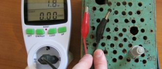
To fix the frequency, a frequency meter is used; this is a special electrical measuring device used to fix the frequency of a periodic process or the frequencies of the harmonic components of the signal spectrum.
One of the main parameters of periodic and pulsating currents is frequency, which determines the number of periodic oscillations per full cycle and is the main characteristic of the SI system of units. The need for an accurate determination of frequency arises in various fields of scientific and practical activity; its determination is of particular importance in electrical engineering, radio electronics, telecommunications, etc.
Frequency meter
Currently, it is possible to measure frequency using a variety of instruments:
- this is also a multimeter
- and a generator with built-in frequency counters
- and oscilloscope
A specialized device that performs time-frequency measurements is a frequency meter.
Classification of frequency meters
Frequency meters are divided depending on the following parameters:
By measurement method:
- frequency counters for direct evaluation (for example, analogue)
- comparison frequency meters (heterodyne, resonant, electronic counting)
According to the physical meaning of the measured quantity, frequency meters are designed to:
- for measuring sinusoidal oscillations (analog)
- measurements of frequencies of harmonic components (resonant, heterodyne, vibration)
- for measuring discrete events (capacitor, electronic counting)
According to their design, they are divided into:
- panel
- portable
- stationary
By area of application:
- electrical measuring (analog dial, resonant frequency meters, and also partially capacitor and electronic counting frequency meters)
- radio measuring (heterodyne, resonant, capacitor, electronic counting frequency meters)
Making money on radio components in Moscow: is it profitable?
The answer to the question posed above and which has long been of interest to citizens involved in this matter, namely: is it profitable to collect and sell radio components in Moscow for purchase, will be definitely positive. This is undoubtedly a truly very profitable business in terms of all possible parameters that concern citizens. After all, prices for even one kilogram of radio components made from precious metals can rise and ultimately reach incredible heights that are even difficult to believe, and collecting a given amount of radio components at the moment, that is, in our days, is quite doable and not the most difficult, according to its essence, a task even for a beginner in this line of work or those who do not like to spend too much effort and a lot of personal time.
What is measured with what, what frequency meters, for what?
With the help of resonant frequency meters, coupled with converters of mechanical vibrations into electrical ones, the frequency of mechanical vibrations is usually measured.
Using electromechanical, electrodynamic, electronic, electromagnetic, magnetoelectric frequency meters, the frequency of electrical oscillations is measured.
Electronic frequency meters (resonant, heterodyne, digital, etc.) are used to measure the frequency of electromagnetic oscillations in the radio frequency and microwave ranges.
The operation of a resonant frequency meter is based on a comparison of the frequency measured with the natural frequency of an electrical circuit (or microwave resonator), which is tuned to resonance with the measured frequency. In heterodyne frequency meters, the measured value is compared with the known frequency (or its harmonics) of the local oscillator (model oscillator). The principle of operation of digital frequency meters is to count the number of periods of measured oscillations over a certain period of time.
By adding appropriate attachments to the electronic frequency meter, it is possible to measure almost any electrical quantity (voltage, current, resistance, capacitance, inductance, etc.).
Regulatory and technical documentation
GOST 8.567-99 GSI. Time and frequency measurements. Terms and definitions GOST 7590-93 Analog indicating electrical measuring devices of direct action and auxiliary parts for them. Part 4. Special requirements for frequency meters GOST 7590-78 Analog indicating electrical instruments for measuring frequency. General technical conditions GOST 22335-85 Electronic frequency counters. Technical requirements, test methods GOST 22261-94 Instruments for measuring electrical and magnetic quantities. General technical conditions GOST 8.422-81 GSI. Frequency meters. Methods and means of verification GOST 12692-67 Resonant frequency meters. Methods and means of verification OST 11-272.000-80 Resonant frequency meters. Main parameters of MI 1835-88 Electronic frequency counters. Verification method
Add a link to a discussion of the article on the forum
RadioKot >Competitions >Congratulate Kot as a human being 2022! >
| Article tags: | Add a tag |
Frequency meter "Fregat"
Author: mig958 Published 09/05/2017 Created using KotoEd. Participant of the Competition “Congratulate the Cat as a Human 2022!”
| You are the smartest and most skillful, One of the best among us! On my birthday I wish - That everything in life would be simple - Cool! |
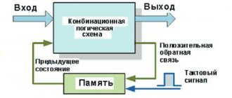
A frequency meter is one of the main equipment of a radio amateur. It’s not for nothing that so many articles are devoted to this popular device. It would seem that there are a huge variety of amateur radio frequency counter circuits to suit every taste. However, almost all of them use the direct counting method, although there is a fairly simple, but much better reverse counting method. A pleasant exception is the FC-510 frequency meter. There is another device that uses almost this method, this is a Simple Frequency Calibrator / Frequency Meter / Reference Clock. But due to the small range of the measured frequency and inconvenient measurement time, it is of little use as a frequency meter. By the way, I assembled it and am very pleased with it. Both the FC-510 and the calibrator use a countdown method. The main advantage of the method is that its relative measurement error does not depend on the value of the input frequency. In general, the author of FC-510 has an excellent document on frequency measurement methods, although it is not finished, but for beginner radio amateurs I have never seen a better presentation of this issue. This frequency meter has only one drawback: it is a bit complicated for a beginner, and even for a mid-level radio amateur. Unfortunately, nothing like this, but it’s simpler, and I didn’t find anything else on the net. An announcement about a competition that caught my eye prompted me to ask the question: why not create something similar but simpler, and the timing of the competition would not allow this process to stretch out, as usual, into infinity. Since I had been thinking about this topic for a very long time, I did not think about the circuit for a long time, nor did I think about the choice of a microprocessor. The block diagram is presented in Figure 1.
Figure 1. Structural diagram
The microprocessor generates a control signal for input D of the trigger (gate), but the counting of pulses itself begins and ends upon the arrival of the edge of the measured signal. By the way, the name Frigate was born from the consonance with the words free gate - free gate, which is the essence of the method. Well, then count the input and reference frequencies and calculate the result. The circuit parameters determine the capabilities of the crystal oscillator (VCTCXO), microprocessor and ease of use of the device.
Main characteristics of the frequency meter:
- Measured frequency range: 1Hz – 100MHz (1GHz with prescaler by 64);
- Amplitude of the measured signal: 0.1 – 10V;
- Reference frequency: 20MHz;
- Measurement time: 5 sec;
- Number of significant figures: 8;
- Measurement error * no more than 10-7;
- Up to 2 MHz measurement by the reverse counting method, above by the direct counting method;
- Current consumption: 50 (80 with backlight) mA;
- Modular design with remote signal conditioners.
* When the reference frequency error is less than 2*10-8.
Scheme and operation:
| The operation of the frequency meter is extremely simple - there are no controls. |
| The schematic diagram of the measuring part is shown in Figure 2. |
Figure 2. Schematic diagram of the measurement module.
The input signal from the shaper goes to the Schmidt trigger DD1. In principle, you can do without it, it only helps to get rid of interference. Next is the gate circuit: the microprocessor generates an exact interval of 5 seconds, which comes to input D of DD2.1 and the first edge of the input frequency switches it, allowing counting of input pulses using DD3.1 with the TMR1 timer, and counting of the reference frequency using DD3.2 timer TMR0. The DD2.2 trigger divides the input frequency by 2, allowing you to raise the measured frequency to 100 MHz (PIC timers are known to operate up to frequencies of 50-60 MHz). At the end of 5 sec. The first edge of the input frequency will switch the flip-flop and end the counting. The microprocessor monitors the formation of the gate to be able to measure from 1Hz (waiting for the end of the period can last up to 1.5 seconds), as well as to exclude emergency situations. If the gate is formed correctly, the pulses from the prescalers are then counted; DD3.3 and DD3.4 are used for this. Since the measurement time is quite long, it is shown on the measurement waiting scale. Next are calculations and display. There is a 5-bit input signal level meter. The voltage from the input driver rectifier is approximately 1-1.5 V. supplied to input RA0. Resistor R5 adjusts the sensitivity. Input RA2 determines the presence of a prescaler (0 prescaler is enabled).
The measured frequency range is divided into 3 parts (remote modules):
- 1Hz – 1MHz:
- 1kHz – 100MHz:
- 70MHz – 1GHz.
Main module: 1kHz – 100MHz. It is assembled according to a long-established scheme and has confirmed its high characteristics: real bandwidth with increased pass capacitors in the range of 0.1-10V. from 100Hz to 150MHz. Scheme in Figure 3.
Figure 3. Schematic diagram of a 1 kHz – 100 MHz driver.
I did not prototype the following modules, due to the lack of microcircuits in my stores. I ordered them on Ali Express. But since they were also not developed by me and are widely used, I think there should not be any special problems. However, the circuit design of remote modules, their frequency breakdown and design (external or internal) can be very diverse. When measuring TTL level signals, you can do without them altogether.
Figure 4. Schematic diagram of a 70 MHz – 1 GHz driver.
Figure 5. Schematic diagram of the 0Hz – 1MHz driver.
I don’t provide the power supply diagram (Transformer, 4 diodes and electrolyte, you can add 7809 or 7812 or...).
Construction and details:
Since I like SMD components (I got rid of the rest a long time ago), the design turned out to be quite compact. I understand perfectly well that repeating one to one is unlikely. Therefore, my design is just one example of a possible solution. Due to its low energy consumption (in the absence of a thermostat), it is even possible to make it in the form of battery-powered tweezers. There are no special design requirements. The only recommendations: due to the high sensitivity to interference, the paths along which the signal passes should be of minimal length and do not use switching stabilizers and converters to power it.
As for the details: You can replace PIC16F876A with 877,886,887 in any package: DIP, SOIC, TQFP. The main element, even more significant than the processor, is the quartz oscillator; it ultimately determines the measurement error. Unfortunately, it is impossible to use a different frequency without deteriorating the parameters of accuracy, error or measurement time. The generator can be of the VCTXCO type (temperature compensated with voltage adjustment) or TXCO (temperature compensated with mechanical adjustment). The generator output must be TTL or CMOS. If there is a sine, you will need a Schmidt trigger, since the signal goes not only to the MK but also to the logic. It is also possible to use a homemade thermostated generator with ordinary quartz, assembled using logic or a transistor (you will need a Schmidt trigger at the output). If you really want to, you can use a quartz oscillator at a different frequency (with some worsening of the error), for example at 10 MHz. In this case, of course, it will be necessary to make corrections to the program. Instead of 74AC74 and 74AC00, you can use other series, for example F, ACT, VHC, with a corresponding change in the maximum frequency. It is also possible to use the K1554, K1594, K1531 series. Instead of 74LVC1G14, it is possible to use any Schmidt triggers of the corresponding series, again look at the frequency. Any power transformer for 2-5 W. with rectified voltage 7 - 12V.
Setting:
Setting the crystal oscillator frequency can be done in two ways:
- By measuring a known exact frequency and adjusting the generator using R4, achieve an indication of the same frequency on the indicator.
- Measuring the frequency of the reference oscillator with a frequency meter that has the required error, and correspondingly adjusting the frequency of the reference oscillator to a frequency of exactly 20 MHz.
Since the development was carried out in a short time, naturally, not all issues were carefully thought out, especially since this is my first experience in programming in C for PIC, I will be grateful for constructive criticism, pointing out errors and inaccuracies, other shortcomings, as well as suggestions for improving the device.
In conclusion, there is a video of the layout working after finishing debugging the program. Well, a few photos of the finished device. I apologize for the quality.
P prompted me to develop:
[1] Interpolating frequency meter FC-510
[2] Typhoon frequency meter
[3] Simple frequency calibrator/frequency meter/reference clock
[4] Simple RF/Microwave Frequency Counter
Files:
Source. C project in MPLAB X v4 compiler XC8 v1.33 Firmware for 876 and 886 Printed circuit boards in Sprint-Layout 6 Proteus v8.6 files. Used at the initial stage of development of Pin-circuit diagrams in SPlan
All questions in the Forum.
| What do you think of this article? | Did this device work for you? | |
| 109 | 4 | 4 |
| 0 | 0 |