Projects of all electrical networks are created on the basis of special technical documentation, which displays the design and operational capacities, parameters and characteristics of the electrical network design of the room or building as a whole. All this documentation is regulated “Rules for technical operation of consumer electrical installations”. The rules are developed on the basis of current legislative acts, state standards and other regulatory and technical documents. The technical operation rules take into account proposals from electrical repair organizations and research institutes. The fundamental document in design documents is the power supply diagram.
Single-line power supply diagram: what is it and why is it needed?
Electrical circuit diagram
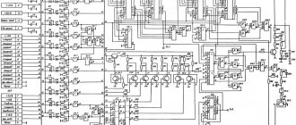
A complete picture of how an electrical product or object functions is provided by a circuit diagram. It includes the entire list of elements that make up the object. This diagram is the basis for the development of all subsequent documents and drawings necessary for the construction of a facility or equipment. The schematic diagram reflects drawings that show the complete electromagnetic and electrical connections of the elements, as well as the characteristics of all components of the object. The schematic diagram is drawn up in two ways: combined and spaced.
With the spaced method, circuits are used that contain many contactors, relays and various contacts. To create such schemes, elements are assigned values sequentially. But the individual circuits are arranged in parallel. All parts that are included in the elements and devices or individual elements on the diagram are drawn separately from each other so that the diagram looks more clear.
With the combined method, the power supply diagram shows all parts of elements or devices close to each other.
On the free fields of diagrams that are made in a spaced manner, it is permissible to place graphic symbols of devices made in a combined way.
If the object contains elements that are partially used, then these elements should be depicted in full on the diagram, and it should be indicated which parts are used in their entirety and which are not. Those that are fully used should be shown longer on the diagram, and parts of unused elements are shown shorter.
What is meant by single line diagram
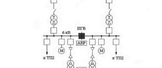
A single-line diagram differs from a schematic diagram in that on a single-line diagram all electrical connections of the object are made in a simplified form and are indicated by one line, regardless of the number of phases. This simplification method is used not only to display power lines, but also to designate different types of cables, the number of wires in which may be more than three.
Creation of electrical circuit diagrams.
For those who know at least a little how to work with Microsoft Word, it will not be at all difficult to create an electrical circuit.
You just need to select the required element in the library, click on it and it will immediately appear in the document. Now all that remains is to arrange the elements entered in this way as you need on the sheet and connect the connection points of the diagram with lines and the diagram is ready! Don't forget to use standard program tools. An example of creating a diagram in Microsoft Word can be seen in Figure 6.
Figure 6. An example of creating a diagram in Microsoft Word.
Key points for designing a single-line power supply diagram
What should a single-line power supply diagram include?
To put the facility into operation, the following steps are required:
- make a request for technical specifications to the power grid organization;
- develop a single-line diagram;
- approve the finished scheme in the organization that issued the technical specifications.
The stages of approval of the as-built scheme are exactly the same as for the design one.
In order to easily go through all the stages of preparing a single-line diagram, it must contain the following information:
- main and backup connection points to the power grid;
- type of input distribution device;
- electricity metering devices;
- methods of laying wires and cables, indicating the brand and length;
- automatic shutdown devices and their technical parameters;
- load on the electrical network indicating power and current;
- lighting circuits.
Design rules, GOST requirements
When drawing up single-line diagrams, it is necessary to comply with the requirements of GOST ESKD (Unified System of Design Documentation), which strictly prescribes the algorithm for creating electrical diagrams:
- GOST 2.702-2011 – provisions for the development of electrical circuits;
- GOST 2.709-89 – wires, contact connections and sections of circuits;
- GOST 2.755-87 – switching devices and contact connections;
- GOST 2.721-74 – designations for general use;
- GOST 2.710-81 – alphanumeric characters.
A thick line in the diagrams highlights all electrical elements and power circuits.
All electrical circuits must be marked. Labels must be assigned sequentially from source to consumer. The circuits are designated with Arabic numerals and capital Latin letters. The numbers indicate the sequence of the circuit, and the letters indicate the phases of the alternating current.
Sections of the circuit with separated contacts (relay windings, resistors, etc.) must be marked taking into account polarity. Positive polarity of circuit sections is indicated by odd numbers, polarity with negative values by even numbers.
Sections of the circuit that pass through different contact connections must have the same symbols. The markings on the diagram are described to the left or above the image of the circuit.
The diagram must indicate the complete characteristics of the input and output electrical circuits. Characteristics mean voltage, resistance, frequency, inductance, current, etc.
How to choose a cable for the network
For a single-phase connection you will need wires with three cores, for a three-phase connection - respectively, with five
When developing a project, it is very important to choose a cable of a suitable cross-section (guided by the PUE). This indicator can be found in special tables, depending on the current strength
The required diameter of the conductor is preliminarily calculated. This is done using the formula d=k×I+0.005. Here k is a constant coefficient for the metal of the conductor. For example, for copper it is 0.034. The letter I denotes the current strength.
View gallery
They sell wires using cross-section rather than diameter as a measurement system. Therefore, it will be necessary to define it further. There is a formula for this: S=0.785×d2.
A preliminary calculation can be made based on the fact that per square millimeter of copper wire there can be 10 A, aluminum - 7 A. In practice, a 2.5 mm2 wire is usually used for sockets, and 1.5 mm2 for lighting.
View gallery
Why do you need an electrical project?
Most often, an electrical project is required when purchasing a new apartment or when building a private house, when internal power supply has not yet been organized and connection to electrical networks is required to begin installation of electrical wiring. An electrical project will also be required during a major overhaul of the apartment, with a major change in the internal wiring.
If you do not have enough power that you initially allocated, you have installed energy-intensive consumers and automatic protective equipment is constantly triggered due to overload, in this case it is also necessary to do an electrical project in order to go through the procedure to increase the allocated power for your facility.
Permitted power (Allocated power) is the power officially certified by the supplier and regulatory authorities that your facility can consume.
In all these cases, the development of the electrical project must be carried out by an official design organization that has all the necessary licenses and permits for the development of electrical supply projects. If the company developing the project does not have the necessary license for this type of activity, it will not be possible to approve such an electrical project.
In addition to the cases listed earlier, when the development of an electrical supply project is mandatory and must be carried out in a strictly established manner, to connect an object to the electrical grid or to increase the allocated power, there are many situations when an electrical project will still be useful to you.
So, for example, during any major renovation of an apartment or house that is already connected to the electrical grid, and the amount of permitted power suits you, in addition to remodeling and changing the interior, a corresponding replacement of electrical wiring and electrical equipment is usually carried out, changing its quantity and location.
In this case, the electrical project will also be extremely useful, because all indicators will be calculated, all loads will be correctly distributed, materials and equipment will be selected. In addition, the electrical supply project will help you more accurately calculate the required amount of work and the amount of materials, will help electricians and electricians not make mistakes during electrical installation, and will make your apartment or house truly electrically safe.
Terms of reference for developing a power supply plan
Before ordering an electrical installation plan for a facility, you need to very carefully consider all the requirements for it and draw up a competent technical specification.
Terms of reference for the development of an electrical project are usually drawn up after the project for the internal design of the facility has been developed and approved.
Example of a home electrical project
Back
Forward
If a serious organization was involved in developing a project for the construction of an object or its reconstruction, then it usually develops the requirements for the power supply plan for the object. You can draw up technical specifications for developing a power supply plan for the facility yourself.
Development of a power supply plan
Only design organizations that have been licensed in the prescribed manner have the right to develop a power supply plan. Organizations and persons who have not passed licensing are prohibited from engaging in this activity. A power supply plan developed by a private individual or organization without a license will not be approved by Rostechnadzor.
Calculation and design of power supply in Moscow from EnergySystems
Regardless of what kind of construction project you own (a workshop of an industrial enterprise, an administrative building, a cottage or an apartment building) and what exactly you are doing with it (building or operating), in order to connect it to the general power grid it is necessary to calculate and design the power supply.
To do this, you need to hire a specialist or seek help from a specialized company, where they will carry out engineering, research, computational, graphic and planning work for you. All of the listed types of work are performed in a certain sequence, and without them it is simply impossible to install the electrical network at the proper level in compliance with all safety standards and regulations.
Basic and additional documents
As mentioned above, the main diagrams of an electrical project include three drawings:
- single line circuit diagram;
- layout of sockets;
- and lighting scheme.
In most cases, this is a sufficient amount of the graphic part of the project. Supplemented with a specification, an explanatory note and a number of calculation tables, it can be submitted for approval.
But in some cases, the project is supplemented with a description of additional systems, which include:
- potential equalization system;
- lightning protection complex;
- external wiring (for cottages and detached buildings);
- backup power supply systems;
- emergency lighting schemes.
Such drawings are filed in a general package of documents, and the explanatory note is supplemented with relevant information.
Please note that if the project provides for transitions to backup or emergency power systems, then both operating modes (operational and emergency) must be displayed on the single-line diagram.
Organizational provisions
Theoretically, any technical design documentation should be developed in accordance with the algorithms set out in the ESKD and go through all stages of detailing:
- development of project documentation (technical proposal, preliminary design, technical design);
- development of design documentation (for a prototype or for serial and mass production).
But in practice, each industry has established its own design format, determined by its specifics, and secured by additional legislative acts.
In most cases, the priority of development is determined by the composition of the final documentation and established calculation algorithms, but in some situations the organizational scheme according to which the design plan is developed is also important.
Industry specificity is especially evident in the field of electrical engineering design, where the volume of design documentation varies in the range from 2-3 sheets to several volumes consisting of diagrams and explanatory notes.
The need to detail the stages of power supply design in organizational terms arose during the development of reference books with coefficients for calculating the cost of work (SBCP).
According to this classification, there are five categories of complexity of electrical projects, each of which has its own composition of project documentation.
The first and second categories allow three combinations of work packages:
- working draft only;
- preliminary and detailed designs;
- feasibility study and detailed design.
The third category of complexity includes projects consisting of two packages: technical design and working documentation.
The development of power supply systems for large administrative or industrial facilities is classified as the fifth category of complexity. In this case, all three stages of design are involved: preliminary design, technical design and working documentation.
Separately, we note that dividing the process of developing an electrical project into several stages is necessary, first of all, to create the possibility of intermediate analysis (both technical and economic).
Electrical projects for private houses and apartments are classified in the third category of complexity, in which the preliminary design stage is reduced to the preparation of technical specifications, and the working draft is the as-built documentation.
