Powerful electrical installations can operate with a voltage of several hundred kilovolts, while the current in them can reach more than ten kiloamperes. Naturally, it is not possible to use conventional instruments to measure quantities of this order. Even if they could be created, they would be quite bulky and expensive.
In addition, when directly connected to a high-voltage alternating current network, the risk of electric shock when servicing the devices increases. The use of measuring current transformers (hereinafter referred to as ICTs) made it possible to get rid of these problems, thanks to which it was possible to expand the capabilities of measuring devices and provide galvanic isolation.
Purpose and device of ITT
The functions of this type of transformer are to reduce the primary current to an acceptable level, which makes it possible to connect unified measuring devices (for example, ammeters or electronic electricity meters), protective systems, etc. In addition, the current transformer provides galvanic isolation between high and low voltage, thereby ensuring the safety of operating personnel. This brief description allows you to understand why these devices are needed. A simplified design of the ITT is presented below.
Design of measuring current transformer
Designations:
- Primary winding with a certain number of turns (W1).
- A closed core made from electrical steel.
- Secondary winding (W2 - number of turns).
As can be seen from the figure, coil 1 with terminals L1 and L2 is connected in series to the circuit where current I1 is measured. Devices that allow you to set the value of current I2, relay protection, automation system, etc. are connected to coil 2.
The main area of application of CT is metering electricity consumption and organizing protection systems for various electrical installations.
In a measuring current transformer, it is necessary to have insulation between the coils, the turns of wire in them and the magnetic core. In addition, according to PUE standards and safety requirements, it is necessary to ground the secondary circuits, which provides protection in the event of a short circuit between the coils.
You can get more detailed information about the principle of operation of CTs and their classification on our website.
How to choose a current transformer for a meter: 10 criteria according to GOST
Long-term and reliable operation of the CT is possible if its design complies with:
- purpose. (We focus only on measuring products);
- the current voltage of the electrical wiring, which can vary from 220 volts to high-voltage values;
- type of insulation;
- acceptable installation method (in closed distribution devices or outdoors);
- the magnitudes of effective currents taken into account by the transformation ratio;
- accuracy class;
- a number of other requirements.
In addition, it will be necessary to clarify the design of the primary winding, which can be manufactured:
- rod or tire;
- with the possibility of installing one turn or several.
To operate different measurement, protection or automation circuits, several secondary windings with different characteristics can be made inside the CT housing. All of them will have to be taken into account, and the unnecessary ones will have to be reliably bypassed.
GOST 7746-2001 Table 5 defines the values of 10 main parameters that ensure reliable operation of CTs as measuring devices for electric meters.
More detailed information is provided within this GOST.
List of main parameters
The technical characteristics of the current transformer are described by the following parameters:
- The rated voltage, as a rule, is indicated in kilovolts in the passport for the device. This value can be from 0.66 to 1150 kV. You can get complete information about the voltage scale in the reference literature.
- The rated current of the primary coil (I1) is also indicated in the passport. Depending on the design, this parameter can be in the range from 1.0 to 40000.0 A.
- The current on the secondary coil (I2), its value can be 1.0 A (for ITT with I1 no more than 4000.0 A) or 5.0 A. Devices with I2 equal to 2.0 A or 2.50 can be manufactured to order A.
- Transformation ratio (CT), it shows the ratio of the current between the primary and secondary coils, which can be represented as the formula: CT = I1/I2. The coefficient determined by this formula is usually called real. But for calculations, the nominal CT is also used, in this case the formula will look like: INOM1/INOM2, that is, in this case we operate not with actual, but with nominal values of the current on the first and second coils.
Below, as an example, is the datasheet of the TT-B model.
List of main parameters of the measuring current transformer TT-V
Purpose of current transformers in simple words
The main task
A current transformer (the abbreviated generally accepted designation CT) is designed to operate in electrical circuits as a simple converter capable of proportionally reducing high currents with high accuracy to nominal secondary values without changing the signal frequency.
A large primary alternating current is supplied to its input, and a reduced, converted load value flows through the output circuit.
This process can be easily represented by combined graphs of sinusoids of both currents with their display on a simple vector diagram of a unit circle.
The sine wave of the primary current I1 passing through the power buses is shown in a graph with a high amplitude, which can exceed, for example, 100 or 200 amperes. Let us assume that it is distant from the origin of coordinates by some angle α.
Its shape and magnitude will be converted in the CT into a secondary quantity I2 with a significantly lower amplitude, for example, 1 or 5 amperes.
Graphs of sinusoidal harmonics are easily simplified by vector expressions constructed on the plane of the unit circle. They make it easier to understand ongoing processes and make it easier to analyze them.
A vector diagram is simply drawn and clearly shows the proportions of the magnitudes of each component and their direction.
Now let’s make a simple conclusion: at any moment ti, the sinusoid I2 repeats the shape of the I1 signal and differs from it strictly by a certain amount, called the transformation coefficient Ktt.
Ktt = I1 / I2
This is how it is written on the body nameplate: by expressing the ratio of the primary current, shown in the first place, to the secondary, for example, 200/5.
In principle, the same technology and markings are used here as a conventional voltage transformer, where volts are shown instead of amperes.
Practical use
Current transformers are created as measuring instruments with certain metrological characteristics. They operate in measurement circuits and protective device circuits.
They are assessed by accuracy classes according to two parameters:
- Deviation of the real amplitude of the secondary current from the calculated value calculated from the transformation ratio.
- Time displacement of the angle of the secondary sinusoid ẟ relative to the primary signal.
For information: as a result of CT transformation, the frequency of the secondary signal does not change, it remains the same. Errors are formed only in the angle ẟ and amplitude, but they are not significant for measurements carried out in household electrical wiring.
Next, we’ll look at the design and operating principles.
Types of instrument transformer designs
Depending on the design, these devices are divided into the following types:
- Reel-to-reel, an example of such a TT is presented below.
Coil ITT
Designations:
- A – Secondary terminal block.
- B – Protective housing.
- C – Contacts of the primary winding.
- D – Winding (loop or figure eight).
- Rod-type , they are also called single-turn. Depending on the design they can be:
- Built-in, they are installed on the bushing insulators of power transformers, as shown in Figure 4.
Figure 4. Example of installing a built-in CT
Designations:
- A – built-in TT.
- B – insulator of the power input of the substation transformer.
- C – location of the CT installation (shown in section) on the insulator. That is, in this case, the high-voltage input plays the role of the primary winding.
- Tire, this is the most common design. Its structural principle is reminiscent of the previous type, the only difference being that in this design, a conductive busbar or core is used as the primary winding, which is inserted into the ICT window.
Busbar CTs manufactured by Schneider Electric
- Detachable. The peculiarity of this design is that the CT magnetic circuit can be divided into two parts, which are tightened together with special pins.
This design option greatly simplifies installation/dismantling.
Design Features
What are these transformers made of? What is the difference between a current transformer and a voltage transformer? The answers to these questions can be found in the description of the design features. Current transformers, their purpose and principle of operation, imply the constancy of certain conditions:
- every CT must have more than one winding on its magnetic core;
- windings that are secondary are certainly connected to the load (Rн);
- resistance Rн should not contain deviations from the TT stated in the documents;
- The primary winding is made as a busbar passing through the core or in the form of a coil.
What is a diode - operating principle and device
The absence of a load on the secondary winding does not ensure the occurrence of magnetic flux F2 in the core, which has a compensating property. This leads to an increase in the temperature of the core and its melting. Heating occurs because F1 becomes too high.
Resistance deviation Rн affects the measurement error and worsens it. If the resistance in the secondary winding is exceeded, the voltage U2 increases and the CT insulation may fail. A breakdown will occur and the device will fail.
Information. Voltage transformers (VTs) differ from CTs in their method of application and connection diagram. They are connected in parallel and are designed to increase or decrease the voltage, decoupling the power circuit from the control and monitoring circuit. The main operating regulations of the fuel pump are close to the idle mode (idle). This is due to the fact that parallel-connected elements of the control circuit consume low current, and their Rн is large.
Classic TT device
Explanation of markings
The designation of domestic models is interpreted as follows:
- The first letter in the model name indicates the type of transformer, in our case it will be the letter “T”, indicating that it belongs to a TT.
- The second letter indicates a design feature, for example, the letter “Ш” indicates that this device is a bus device. If the letter “O” is indicated, then this is a reference CT.
- The third letter encrypts the isolation performance.
- The numbers indicate the voltage class (in kV).
- Letter to indicate climatic version according to GOST 15150 69
- CT, indicating the rated current of the primary and secondary windings.
Let us give an example of deciphering the markings of a current transformer.
Label on the TT indicating its brand
As you can see, the figure shows the marking TLSh 10UZ 5000/5A, this indicates that we have a current transformer (the first letter T) with cast insulation (L) and a busbar structure (Sh). This device can be used in a network with voltage up to 10 kV. As for the design, the letter “U” indicates that the device was created for use in a temperate climate zone. KT 1000/5 A, indicates the value of the rated current on the first and second windings.
Possible faults
Errors in the installation and connection of current transformers, as well as incorrectly selected equipment, cause CT malfunction.
Important! Troubleshooting should begin if the secondary current of the CT is not combined with the primary. A current that is too low and does not correspond to the stated ratio indicates damage to the device.
Evidence of a transformer malfunction is:
- crackling and increased noise during operation;
- the appearance of sparks from the winding on the housing or on the terminals;
- smoke or smell of burning insulation;
- excessive heating of device parts.
A faulty device may produce distorted measurement results, which will cause false activation of protective equipment and incorrect metering of electricity. Periodically, at substations, element-by-element (phase-by-phase) verification is carried out with the measurement of currents under load. The calculated values obtained from the measurement data must coincide with the measured values at the CT output. The permissible error is no more than 10%.
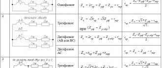
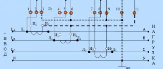
Connection diagrams
The windings of three-phase CTs can be connected in delta or star (see Fig. 8). The first option is used in cases where it is necessary to obtain a higher current strength in the circuit of the second winding or it is necessary to phase shift the current in the secondary coil relative to the primary one. The second connection method is used if it is necessary to monitor the current strength in each phase.
Figure 8. Connection diagram of a three-winding CT with star and delta
If there is an isolated neutral, a circuit can be used to measure the current difference between the two phases (see A in Fig. 9) or a partial star connection (B).
Figure 9. Connection diagram of a CT for a difference of two phases (A) and a partial star (B)
When it is necessary to power the ground fault protection, a circuit is used that allows the currents of all phases to be summed (see A in Fig. 10). If a current relay is connected to the output of such a circuit, it will not respond to a short circuit between phases, but will definitely work if a ground fault occurs.
Fig. 10. Connections: A – for the sum of currents of all phases, B and C – serial and parallel connection of two-winding CTs
In conclusion, we give two more examples of connecting the secondary windings of a CT to take readings from one phase:
The secondary coils are connected in series (B in Fig. 10), making it possible to measure the total power.
The secondary windings are connected in parallel, which makes it possible to reduce the CT, since the current in these coils is summed, while in the line this indicator remains unchanged.
How the device works
When it became clear what transformation is, it’s time to take a closer look at the operating principle of the current transformer.
Connecting the current transformer
Two windings are placed on a closed core (magnetic circuit) assembled from plates. The first coil is connected in series to the load power circuit. The secondary coil is connected to the meters with its terminals. The core is assembled from cold-rolled silicon steel plates.
For your information. Electricity metering is done in exactly this way. Current transformers are included in single-phase and three-phase circuits, which allow readings to be taken for each phase, feeding data to the meter.
When alternating electricity passes through the turns of the first (main) winding, an alternating magnetic flux F1 is formed around it. Flow F1, penetrating all windings of the transformer, induces EMF (E) in them. In this case, E1 and E2 appear. When any load is connected to the secondary winding circuit, electricity will begin to flow through it.
Operating principle of TT
Choice
When choosing a current transformer, first of all, it is necessary to take into account the rated voltage of the device is not lower than in the network where it will be installed. For example, for a three-phase network with a voltage of 380 V, you can use a CT with a voltage class of 0.66 kV; accordingly, for installations over 1000 V, such devices cannot be installed.
In addition, INOM CT must be equal to or exceed the maximum current of the installation where the device will be operated.
Let us briefly outline other rules that allow you not to make a mistake when choosing a TT:
- The cross-section of the cable that will connect the CT to the secondary load circuit should not lead to losses in excess of the permissible norm (for example, for accuracy class 0.5, losses should not exceed 0.25%).
- For custody transfer metering systems, devices with a high accuracy class and a low error threshold must be used.
- It is allowed to install current transformers with an increased CT, provided that at maximum load the current will be up to 40% of the rated one.
You can view the norms and rules by which measuring current transformers (including high-voltage ones) are calculated in the PUE (clause 1.5.1.). An example of the calculation is shown in the picture below.
Example of current transformer calculation
As for choosing a manufacturer, we recommend using branded products whose advantages have been proven over time, for example ABB, Schneider Electric b, etc. In this case, you can be sure that the technical data indicated in the passport and the test methodology complied with the standards.
How current transformers work: brief information for beginners
The design of the TT is explained in the picture below.
Inside a housing made of non-flammable dielectric material, for example, plastic that does not support combustion, there are:
- primary winding, made of a busbar with holes for bolted mounting to the power circuit;
- magnetic circuit assembled from laminated plates of electrical iron;
- a secondary winding wound with turns of copper wire over an insulated magnetic circuit. The outside of the copper is coated with a layer of varnish with high dielectric properties;
- terminal pins for connecting installation wires of the secondary circuit.
The number of turns of the secondary winding determines the value of the transformation ratio, and its cross-section is selected according to the load in nominal and emergency modes.
For individual measuring CTs, instead of the primary winding, a through hole is immediately created in the housing, through which the power bus of the distribution cabinet or a powerful wire is passed. That's what they call them: tires.
Among such designs, there are models with a detachable core, which allows you to quickly put on and remove CTs and perform measurements without performing additional preparatory work. Conventional electrical clamps work on this principle.
I show them here because they can be used to carry out the same measurements as CTs permanently installed for connection to electricity meters. Using them, a control measurement of the primary and secondary load passing through the measurement circuits is carried out.
How a current transformer works in the electrical circuit of a meter: a sequential explanation with demonstration with visual pictures
Power current I1 flows through the primary winding from the power supply organization to consumers. It overcomes the electrical resistance of the connected busbars.
A rotating field is formed around the conductor with a magnetic flux fe1 located perpendicular to the movement of the vector I1.
It penetrates the iron of the magnetic circuit and is captured by it. Magnetic flux F1 is induced inside the core.
This orientation scheme ensures minimal energy losses spent on transformations of electromagnetic fields.
Magnetic flux F1, crossing the turns of the secondary winding located perpendicular to it, creates an electromotive force E2 in them. Under its influence, an electric current I2 arises in a secondary coil closed to the measuring device according to Ohm’s law.
I2 overcomes the impedance of the secondary winding and the load connected to it. It can be the current coil of an ammeter, an electromagnetic relay or an electric meter.
A sinusoid flows through the winding of the measuring device, reduced strictly by the value of the CT transformation ratio. Its value is set during the design of devices, and is measured during adjustments and checks of the operation of the electrical circuit.
What 2 dangers exist when operating current transformers: it is important to know them
What happens when the insulation breaks down or is damaged?
The CT core is made of electrical steel with good conductivity. It is covered with a dielectric layer that separates the primary and secondary electrical circuits, but connects them with magnetic flux.
This layer can be accidentally damaged for various reasons. Then the high potential of the primary circuit flows to the secondary circuit.
Hazardous potential can not only damage less protected measuring equipment, but also cause serious damage to human health and cause electrical injuries.
To prevent this phenomenon, all CT secondary circuits must be grounded.
It is designed to safely remove random potential from operating equipment to the grounding circuit of the building and beyond.
Operation of CT secondary circuits without their grounding is prohibited by electrical installation safety rules.
Why is the operating mode dangerous when the secondary circuit is open?
The PUE places increased demands on the installation and strength of CT secondary circuits. They must be made with copper wire with a cross-section of at least 2.5 mm square.
When current I1 passes through the primary winding, energy flows in the secondary circuit with a very high voltage potential. In operating mode, it is always short-circuited, and if it is opened, a high-voltage voltage of several kilovolts immediately appears at the break.
It is dangerous both for low-voltage equipment and for people nearby. Therefore, CTs, even those put into reserve, are prohibited from being left with open terminals . They should always have a reliable shunt short circuit.
The operation of CT secondary circuits without their grounding, as well as the presence of breaks and unreliable connections in them, are considered gross violations of current safety rules.
CTs are widely used not only in the 0.4 kilovolt network, but also in all high-voltage circuits. They not only perform the task of accurately measuring current loads, but also ensure reliable operation of protection systems and emergency automation in the event of emergency conditions.
Typically, for all circuits above 1000 volts, CTs are made as combined devices consisting of one power primary winding and two or more secondary windings:
- one is created to perform the most accurate measurements and is connected to ammeters, wattmeters, meters, recorders and other measuring instruments;
- others are used for reliable operation in the event of emergency conditions and are used in relay protection or automation circuits (accuracy class P).
Current transformers of high-voltage equipment, in accordance with the current voltage of the electrical installation, can be located in special closed cells or mounted on open switchgears.
Service
It is necessary to pay attention that if the mode and operating conditions are observed, the ratings are correctly selected and regular maintenance, the CT will serve for 30 years or more. To do this you need:
- Pay attention to various types of faults; note that most of them can be detected by visual inspection.
- Monitor the load in the primary circuits and prevent overload above the established norm.
- It is necessary to monitor the condition of the primary circuit contacts (if any) and there should be no external signs of damage.
- Equally important is monitoring the condition of the external insulation; in almost half of the cases, its resistance is impaired due to the accumulation of dirt or moisture, which short-circuits the contacts to the ground.
- For oil transformers, check the oil level, its cleanliness, presence of leaks, etc. Maintenance of such installations is practically not very different from other power plants, for example, NDE capacitive transformers; the difference lies in small technical details.
- CT verification must be carried out in accordance with current standards (GOST 8.217 2003).
- If a malfunction is detected, the device is replaced. The damaged CT is sent for repair, which is carried out by specialized services.
Design requirements
When choosing a design, they start from what the transformer is needed for. Why install a busbar or feed-through CT if the voltage with which it will have to work lies in the range from 1 to 3 kV?
The requirements include the following items:
- the selected device must be suitable for the operating conditions and installation location;
- for outdoor use, the transformer terminals must contain protective covers;
- winding terminals must be marked;
- availability of gripping points for lifting heavy vehicles (more than 50 kg);
- grounding sign at the point where the grounding conductor is connected.
All winding contact terminals are made in accordance with the requirements of GOST 10434-82 (for indoor installation) and GOST 21242-75 (for outdoor installation).
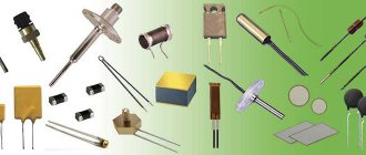
Sensors and microcontrollers. Part 3. We measure current and voltage
We are moving on to the final part of the sensor review cycle, in which we will look at DC and AC current and voltage sensors. For all other sensors that were not included in the main series, we will make additional reviews when they are suddenly needed in future articles. This article opens a new series of materials about measuring power quality parameters, which will include issues of connecting current and voltage sensors to a microcontroller, consideration of algorithms for the operation of power quality analyzers, the meaning of certain power quality indicators and what they mean. In addition, we will touch upon the topic of concern to many about the accuracy of digitization and data processing, mentioned in the comments to the first article.
Content
Part 1. Mat.
Part. It considers a sensor that is not tied to any specific measured parameter.
The static and dynamic characteristics of the sensor are considered. Part 2. Climate control sensors.
It discusses the features of working with temperature, humidity, pressure and gas composition sensors
Part 3. Sensors of electrical quantities.
In this part I will look at current and voltage sensors
ATTENTION: Do not insert knitting needles into the socket. Do not get into the 220V network without the necessary skills!
There is direct current, there is alternating current. Everything happens at once, which sometimes brings a lot of problems. But more on that later. First, let's understand the terminology.
Figure 1: voltage in alternating current circuits
When measuring alternating current, we have 4 different values that will guide us when taking measurements.
All the formulas and terms below apply to the current meter. 1. The instantaneous voltage value
is the potential difference between two points.
Measured at a specific point in time. This value is the basis for all other calculations. In fact, our task will be to read a sequential set of instantaneous voltage values at regular intervals in order to subsequently obtain some other data with their help. u = u(t)
(1) You will get approximately the following graph:
Figure 2: Measuring a series of instantaneous voltage values
When choosing the sampling frequency of sensors, we are guided by the Kotelnikov-Shannon theorem, when in order to restore a signal with frequency f it is necessary to read with a frequency greater than 2f.
I note the need for strict inequality, i.e. if we need to digitize a signal with a frequency of 50 Hz, then reading must be done with a frequency of at least 101 Hz. But, of course, the more the better. If we recall GOST for power quality indicators, then in the Harmonics section we will find that harmonics up to 40, i.e. up to 2 kHz, are interesting for our measurement. And electricity meter chips read at a frequency of 4096 times per second. The power of two was chosen to allow the use of fast Fourier transform algorithms. Having this large set of data collected per unit of time, for example, 1s, we move on to the following: 2. The amplitude value of the voltage
- which is defined as the maximum absolute value from our sample: (2) where [u(t)] is an array with data.
For harmonic vibrations, this value is used in the following formula: (3) 3. Average voltage value,
i.e. Arithmetic mean, i.e. constant component of alternating voltage.
(4) Where is the sampling period of the analog signal. I intentionally write the sum instead of the integral. In a commercial AC network, the average value should be zero. If this condition is not met, there may be certain problems, since the direct current biases the transformers, introducing them into saturation, or heats up the supply line. The latter, by the way, can be useful for solving the problem of frozen ice on wires - the wire is heated and the ice falls off. In low-current analog circuits, the DC component is very present and can be very useful. And if she bothers us, we will quickly get rid of her, but more on that later. 4. RMS voltage
. - also known as effective voltage - on a linear resistive load it does the same work as a DC voltage of the same level. It is determined by the following formula: (5) When measuring the voltage in an outlet, as a rule, we are interested in precisely this actual voltage, which is 230/380V. The amplitude and effective values of the sinusoidal voltage are related to each other through. When designing a measuring system, we will be primarily interested in the amplitude value of voltage and current. During measurements we will be guided by one of the following schemes:
Figure 3: Connecting measuring instruments
A puzzle for the mind - both connection schemes are correct, but under what circumstances is it important to choose the right one? Answers in the comments.
Voltage sensors
First of all, let's measure the voltage. All of the following applies to voltages no less than the supply voltage of the ADC of our controller. Thus, we need to measure a voltage with an amplitude greater than the ADC can chew. Therefore, the voltage level must be lowered - i.e. weaken the signal. For low voltages (for example, like the thermoEMF of a thermocouple from the previous article), the inverse problem is needed - signal amplification. This is a more complex task and we will definitely return to it in future articles. Let's set the condition for calculating our sensors: Measured voltage: alternating, 0-1000V, frequency 50/60Hz. For a three-phase voltage of 380V, the amplitude is almost 600V, but there are networks for 660V. So let it be. In fact, I took this calculation from my piece of hardware and I’m too lazy to redo it. Output voltage ± 1.65V - half of supply +3.3V
Voltage divider
The simplest way would be a voltage divider.
Figure 4: Voltage divider
The voltage on our measuring device will be determined as the input voltage multiplied by the divider factor: (6) When choosing the resistance of the resistors, it is necessary to determine the following requirements: 1. The current through the resistor circuit must be 1-2 orders of magnitude greater than current of our measuring device so that this current does not affect the readings. The meter has a finite resistance value and it turns out that another resistor is connected to resistor R2. The greater the internal resistance, the closer the total resistance is to resistance R2. The resistance of the internal circuits of the ATmega ADC is, for example, 100 MOhm. 2. The power released on our divider should not be too large 3. The applied input voltage should be less than the breakdown voltage of the resistor. Let the current through our doer be 1mA. Then, the total resistance of the resistors will be equal to: (7) Let's determine the required transmission coefficient of our divider: (8) Based on a number of values of resistors E24, choose the closest value that gives about 1 MOhm: R1 = 990 kOhm (three resistors of 330 kOhm each) then resistor R2 = K · R1 = 1.63 kOhm From the E24 series, select the second resistor R2 = 1.6 kOhm. Let's check the coefficient: (9) The error is with the previously calculated 2.3%, which suits us perfectly. In fact, you can accurately select resistors from the E192 series, but in my case this is not necessary - a voltage of 1000V at the input is an abnormal mode, and the system will still be calibrated later. The measuring circuit will look like this:
Figure 5: Voltage Meter Circuit
When designing a voltage divider for large operating voltages, it is necessary to take into account the maximum permissible voltages for the resistors used. For example, the rated operating voltage for SMD resistors is 15 V (0201); 50 V (0402, 0603); 150 V (0805); 200 V (1206, 2010, 2512), And the maximum permissible is 50 V (0201); 100 V (0402, 0603); 200 V (0805); 400 V (1206, 2010, 2512). That is why I use three series-connected resistors of size 1206 - they fit into 555 volts of operating and 1000V of maximum permissible. Of course, all these resistors must be high-precision, since the accuracy of the measurement depends on their resistance and the thermal stability of this resistance. A low-pass filter is assembled on the basis of the R4-C1 chain so that we are not afraid of any interference. By the way, we can quickly see what this filter does:
Figure 6: Frequency response of the filter
As can be seen from the LFC graph, for the operating frequency range from 0 to 2000 Hz, the filter practically does not spoil the amplitude and phase of the signal.
But interference at frequencies of about 100 kHz and higher, emanating from RF converters, is reliably suppressed. So everything is great. Advantages:
- wide range of voltages and frequencies, determined by resistor values;
- high accuracy, again determined by the accuracy and thermal stability of the resistors;
- measures DC and AC voltage.
Flaws:
- there is no galvanic isolation - when interacting with an industrial network, it is necessary to provide protection for the user from electrical circuits, or use galvanic isolation;
- low efficiency - all the divider current goes into heat;
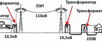
Voltage transformer
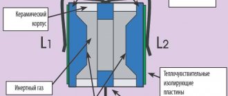
Figure 7: Voltage transformer
For cases where it is necessary to measure very high voltages, 6/10 kV and above, a voltage transformer is used. In fact, it is a conventional transformer, the main operating mode of which is no-load mode.
The accuracy class of such a transformer depends on the working area of the magnetization characteristic. After all, we need to pass through it not just a signal with a certain amplitude, but also not spoil its shape. This is precisely the problem - most voltage transformers practically do not allow harmonics to pass through. It's all about the metal core and magnetization reversal losses. Moreover, the thinner the core plates. the better its frequency characteristics. The usual transformer accuracy class is 0.5, 1, 3. Advantages:
- a huge range of operating voltages - up to hundreds of kilovolts and above;
- much needed galvanic isolation.
Flaws:
- operates on a specific frequency band;
- works only with alternating voltage;
The last drawback is slightly far-fetched, since if necessary, you can use a DC measuring transformer. Yes, DC transformers "exist", but the correct name for the device is a magnetic amplifier. The accuracy and linearity of such devices leaves much to be desired - the work occurs in the area where the core is saturated with magnetization. It looks like this:
Figure 8: Measuring direct current using a magnetic amplifier
You can read about this miracle of technology here: analogiu.ru/6/6-2-2.html If the topic is interesting, I’ll post a review of these old regulators.
Electronic isolated sensor
The electronic isolated sensor does not have the disadvantages of both circuits. In fact, it is a complete device. Inside which there is a voltage divider, and operational amplifiers, and a galvanic isolation unit and an isolated power supply circuit for all this disgrace:
Figure 9: Block diagram of an electronic isolated sensor
I only came across industrial sensors with a voltage output of 0-10V or a current of 0-10mA. Unlike previous sensors, it produces a unipolar signal. In principle, such a scheme can be developed independently, using, for example. an isolated analog amplifier like the HCPL-7850. The main disadvantage of the scheme is that it is very complicated and very expensive. And as Comrade rightly notes in the comments. progchip666
It is extremely difficult to transmit an analog signal with an accuracy of even one percent over a galvanically isolated interface, so often in this case it is necessary to convert it into digital and distill it in this form. Unfortunately, power must also be supplied to the amplifier shown in the diagram. Of course from a galvanically isolated source.
Advantages:
- galvanic isolation;
- high accuracy;
- wide range of voltages and frequencies;
- measures DC and AC voltage.
Flaws:
- expensive;
- complex circuitry.
Additional links
current and voltage sensors ABB www.power-e.ru/2006_03_56.php current and voltage sensors LEM www.sensorica.ru/pdf/LEM.pdf Electricity meters STMP32 www.compel.ru/lib/ne/2015/4/2 -dlya-odnofaznyih-i-mnogofaznyih-schetchikov-novyie-izmeritelnyie-mikroshemyi-ot-st ru.wikipedia.org/wiki/Electrical_voltage
Current sensors
Measuring shunt
The simplest and most accurate way to measure current. As you know, when current flows through an active resistance, a voltage drop occurs across it, proportional to the measured current. Great, we take a resistor and place it in the open circuit of the measured circuit:
Figure 10: Current sensor - current shunt
The voltage drop across the shunt is proportional to the current passed through: (10) Accordingly, depending on the required voltage at the sensor output, we select the required shunt resistance. But! A voltage drop across the shunt will lead to power losses generated as heat; therefore, at high currents, we are forced to be content with low voltage values from the sensor in order to limit losses. These commercially produced ShSM type shunts provide a standard output voltage of 75 mV at rated current:
Figure 11: Current shunt type ShSM
Most measuring heads for shunts are calibrated for a voltage of 75 mV. Pay attention to the second pair of screws - they are designed specifically for connection to a measuring device to improve measurement accuracy by separating the currents of the power and measuring circuits... To measure current using such shunts, you need to use operational amplifiers. At the same time, the average gain is 20-40, which is within the capabilities of widely used operational amplifiers. In principle, in non-critical DC circuits you can use an amplification stage based on a single transistor. The linearity of such a circuit will be poor, but for threshold protection circuits it is a simple and reliable option. We get the following diagram:
Figure 12: Using an op-amp as an amplifier It should be taken into account that when measuring alternating current, the output signal will be bipolar and the operational amplifier must be powered from a bipolar power source. Just in case, let's see how our scheme works:
Figure 13: Simulation of a current sensor amplifier
We apply 75 mV to the input, multiply by 20, and at the output we have a signal with an amplitude of 1.5 V for a current of 10 A.
In the next article we will figure out why a bipolar signal can be inconvenient. Advantages
:
- high accuracy;
- wide range of voltages and frequencies;
- measures direct and alternating current.
Flaws:
- there is no galvanic isolation;
- low efficiency.
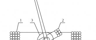
Instrument current transformer
A measuring current transformer is a transformer, the primary winding of which is connected to a current source, and the secondary winding is connected to measuring instruments or protective automatic devices. Current transformers are used to measure currents in high-current circuits, often at high potential. For example, we wanted to measure the current in a 10 kV network. Or, we want to get a simple and relatively cheap way of galvanic isolation of the measured current circuit of our 220V device. The main problem with current transformers is that they can only measure alternating voltage. The current transformer is always loaded. If the secondary winding of the current transformer is open-circuited, then a potential of a couple of thousand kilovolts will arise on it, which will injure personnel and disable the device by breaking through its insulation. Transformers come with a built-in primary winding. For example, these: Figure 14: Current transformer of the CS2106L series from Coilcraft
Or these elephants, which have a semblance of a primary winding in the form of a huge bus, or even a window for passing wires through it
Figure 15: Multi-Amp Industrial Current Transformer
The main disadvantage of a current transformer is that it only operates at a specific frequency of 50, 60 or 400Hz due to the metal core. Of course, a current transformer is capable of transmitting a signal of a higher frequency, but with much less accuracy. In this case, you should pay attention to the thickness of the sheet of the core used - the thinner the iron in the current transformer, the higher the maximum permissible operating frequency. By the way, there are current transformers made of ferrite, which are used to measure systems with a frequency of 50-60 kHz or more. For example, the CS1 series from Coilcraft is designed to operate in the range of 20-50 kHz and can be used in switching power supplies. But if we remove it, we get an air transformer, or so-called. Rogowski coil:
Figure 16: Rogowski coil connection diagram
Unlike other sensors that require interaction with the measured circuit, the Rogowski coil can be installed on top of the wires of the measured circuit like a belt. Some measuring instruments are equipped with the following sensors:
Figure 17: Rogowski coil sensor
The range of measured currents is from tens to thousands of amperes, but they suffer from low accuracy.
Advantages:
- galvanic isolation;
- work with high currents of thousands of Amperes;
Flaws:
- measures only alternating current in a certain frequency range (except for the Rogowski coil);
- changes the phase of the signal and requires compensation
Hall effect current sensors
Sensors of this type use the effect of a potential difference occurring when a current-carrying conductor is placed in a magnetic field. Figure 18: Hall effect
When creating a sensor, we take a magnetic circuit, pass the wire of the circuit being measured through it and place a Hall sensor in the section of the magnetic circuit, obtaining an open-type current sensor:
Figure 19: Open type Hall effect current sensor
The advantage of such a sensor is its simplicity. The disadvantage is the presence of core magnetization, therefore increasing the nonlinearity of the readings. Let's add a winding to the core and pass through it a current proportional to the measured current:
Figure 20: Compensation type Hall effect current sensor
With zero core bias we increase the linearity of the sensor and its accuracy class. However, in its design, such a sensor is close to current transformers, and accordingly its cost increases significantly. Like transformers, there are types of sensors that allow you to pass a power wire through them:
Figure 22: Hall effect current sensor
There are sensors with a split core - but their cost is simply off the charts. Sensors with an integrated power circuit based on the Hall effect with galvanic isolation of 2.1 kV and 3 kV are produced by Allegro. Due to their small size, they do not provide high accuracy, but they are compact and easy to use.
Figure 23: Allegro ACS754 current sensor
- ACS712 sensor – measurement of direct and alternating current up to 30A with an accuracy of ± 1.5%
- ACS713 sensor – optimized for DC current measurement up to 30A. Has twice the sensitivity of its universal counterpart.
- ACS754 sensor – measurement of direct and alternating current up to 200A with an accuracy of ± 1.5%
- ACS755 sensor – optimized for DC current measurement.
- Sensor ACS756 is a sensor for measuring direct and alternating current up to 100A with a supply voltage of 3-5V.
Figure 24: Sensor output voltage versus current Advantages
:
- wide range of measured currents with frequencies up to 50-100 kHz and higher;
- measures direct and alternating current.
- galvanic isolation
Flaws
:
- Expensive
Additional links:
DC instrument transformers analogiu.ru/6/6-2-2.html Rogowski coils www.russianelectronics.ru/leader-r/review/2193/doc/54046 Hall effect on Wikipedia: ru.wikipedia.org/wiki/Hall_Effect Hall sensors robocraft.ru/blog/electronics/594.html Danilov A. Modern industrial current sensors www.soel.ru/cms/f/?/311512.pdf Design of circuits based on the analog amplifier HCPL-7851 www.kit-e. ru/assets/files/pdf/2010_04_26.pdf
Conclusion
I set myself the task of making a review of the sensors most commonly used by the community when developing various devices. Most of the sensors were not included in the cycle only for the reason that they will not be needed in the near future for my materials, but some of them are in the plans. I will definitely make a separate material with acceleration and angular velocity sensors, a compass and examples, so stay tuned for new articles!