If for an ordinary person the perception of information occurs by reading words and letters, then for mechanics and installers they are replaced by alphabetic, digital or graphic symbols. The difficulty is that while the electrician completes his training, gets a job, and learns something in practice, new SNiPs and GOSTs appear, according to which adjustments are made. Therefore, you should not try to learn all the documentation at once. It is enough to gain basic knowledge and add relevant data as you work.
Introduction
For circuit designers, instrumentation mechanics, electricians, the ability to read an electrical diagram is a key quality and indicator of qualification. Without special knowledge, it is impossible to immediately understand the intricacies of designing devices, circuits and methods of connecting electrical units.
Symbols can be considered a special cryptographic code that explains the operation and principle of operation of a particular scheme. In Japan, the USA and Europe, icons differ significantly from domestic markings, which must be taken into account.
Functional shortcuts for the Fn key
On Samsung laptops
- Fn + F1 – Opens the system settings service.
- Fn + F2 – Decrease display brightness.
- Fn + F3 – Increases display brightness.
- Fn + F4 – Switches the desktop to the second monitor.
- Fn + F5 – Disable the touchpad (touchpad).
- Fn + F6 – Mute sound.
- Fn + F7 – Decrease sound volume.
- Fn + F8 – Increase sound volume.
- Fn + F11 – Activates the fan at full power.
- Fn + F12 – Activate the Wi-Fi wireless network adapter.
On Lenovo laptops
- Fn + F1 – Mute sound.
- Fn + F2 – Decrease sound volume.
- Fn + F3 – Increases sound volume.
- Fn + F4 – Healing the DVD drive.
- Fn + F6 – Turns off the display power.
- Fn + F7 – Activate the Wi-Fi wireless network adapter.
- Fn + F8 – Mute the microphone.
- Fn + F9 – Turn off the camera.
- Fn + F10 – Switches the desktop to the second monitor.
- Fn + F11 – Decrease display brightness.
- Fn + F12 – Increases display brightness.
On HP laptops
- Fn + F1 – Call up the support directory.
- Fn + F2 – Decrease display brightness.
- Fn + F3 – Increases display brightness.
- Fn + F4 – Disable the touchpad (touchpad).
- Fn + F6 – Rewind in video, music.
- Fn + F7 – Stop video and music playback.
- Fn + F8 – Fast forward in video, music.
- Fn + F9 – Decrease sound volume.
- Fn + F10 – Increase sound volume.
- Fn + F11 – Mute sound.
- Fn + F12 – Activate the Wi-Fi wireless network adapter.
On ASUS laptops
- Fn + F1 – Enter sleep mode.
- Fn + F2 – Activate the Wi-Fi wireless network adapter.
- Fn + F3 – Decrease the brightness of the keyboard backlight.
- Fn + F4 – Increases the brightness of the keyboard backlight.
- Fn + F5 – Decrease display brightness.
- Fn + F6 – Increases display brightness.
- Fn + F7 – Turn off the display power.
- Fn + F8 – Switches the desktop to the second monitor.
- Fn + F9 – Disable the touchpad (touchpad).
- Fn + F10 – Mute sound.
- Fn + F11 – Decrease sound volume.
- Fn + F12 – Increase sound volume.
On Acer laptops
- Fn + F3 – Activate the Wi-Fi wireless network adapter.
- Fn + F4 – Enter sleep mode.
- Fn + F5 – Switches the desktop to the second monitor.
- Fn + F6 – Turns off the display power.
- Fn + F7 – Disable the touchpad (touchpad).
- Fn + F8 – Mute sound.
- Fn + F12 – Activate the Scroll Lock key.
Types and types of electrical circuits
Before you begin to study the existing symbols of electrical equipment and its connections, you need to understand the typology of circuits. On the territory of our country, standardization has been introduced according to GOST 2.701-2008 dated July 1, 2009, according to “ESKD. Scheme. Types and types. General requirements".
Based on this standard, all schemes are divided into 8 types:
- United.
- Located.
- Are common.
- Connections.
- Installation connections.
- Completely principled.
- Functional.
- Structural.
Among the existing 10 species indicated in this document, the following are distinguished:
- Combined.
- Divisions.
- Energy.
- Optical.
- Vacuum.
- Kinematic.
- Gas.
- Pneumatic.
- Hydraulic.
- Electrical.
For electricians, it is of greatest interest among all the above types and types of circuits, as well as the most popular and often used in work - an electrical circuit.
The latest GOST, which came out, has been supplemented with many new designations, current today with code 2.702-2011 dated January 1, 2012. The document is called “ESKD. Rules for the execution of electrical circuits” refers to other GOSTs, including the one mentioned above.
The text of the standard sets out clear requirements in detail for electrical circuits of all types. Therefore, when performing installation work with electrical circuits, this document should be used as a guide. The definition of the concept of an electrical circuit, according to GOST 2.702-2011, is as follows:
“An electrical diagram should be understood as a document containing symbols of parts of a product and/or individual parts with a description of the relationship between them and the principles of operation from electrical energy.”
Once defined, the document contains rules for the implementation on paper and in software environments of contact connection designations, wire markings, letter designations and graphic representations of electrical elements.
It should be noted that most often only three types of electrical circuits are used in home practice:
- Mounting - for the device, a printed circuit board is shown with the arrangement of elements with a clear indication of the location, rating, principle of fastening and connection to other parts. Electrical wiring diagrams for residential premises indicate the number, location, rating, connection method and other precise instructions for the installation of wires, switches, lamps, sockets, etc.
- Fundamental - they indicate in detail the connections, contacts and characteristics of each element for networks or devices. There are complete and linear circuit diagrams. In the first case, control, control of elements and the power circuit itself are depicted; in a linear diagram, they are limited only to the circuit with the remaining elements depicted on separate sheets.
- Functional - here, without detailing the physical dimensions and other parameters, the main components of the device or circuit are indicated. Any part can be depicted as a block with a letter designation, supplemented by connections with other elements of the device.
Operating principle
Such a device is a switching device, thanks to which the electric current is controlled and distributed along the circuits to which it is connected.
On the one hand, at the push-button station there are power contacts, which perform switching on, switching, normal and emergency shutdown of the equipment.
On the other hand, an electromagnetic coil is installed, due to which these contacts are switched on and off:
- In the first part, these power contacts, as a rule, are movable and are located on a dielectric traverse. If these elements do not have such a characteristic as mobility, then they are placed directly on the body, which must also be dielectric. With their help, power lines are connected. In a calm state, such contacts are open, and no electric current flows through them. There is no load on them in this state. They are held in this state thanks to a special spring;
- The second part is equipped with an electromagnetic coil. Until a sufficient amount of voltage is applied to it, it is also at rest. When the voltage increases, an electromagnetic field appears on the coil circuit, creating an electromotive force. Due to it, a movable core or armature with power contacts attached to it approaches the coil. As a result, the circuits connected through them are closed and a workload is formed.
- When the voltage is removed from the coil, the electromotive force disappears, and the armature cannot be held in the active position; under the action of the spring, it has to return to its original position. As a result of this, the power contact circuits open and the installation stops working.
Graphic symbols in electrical diagrams
The documentation, which specifies the rules and methods for graphically designating circuit elements, is represented by three GOSTs:
- 2.755-87 – graphic symbols of contact and switching connections.
- 2.721-74 – graphic symbols of parts and assemblies for general use.
- 2.709-89 – graphic symbols in electrical diagrams of sections of circuits, equipment, contact connections of wires, electrical elements.
In the standard with code 2.755-87, it is used for diagrams of single-line electrical panels, conventional graphic images (CGI) of thermal relays, contactors, switches, circuit breakers, and other switching equipment. There is no designation in the standards for automatic devices and RCDs.
On the pages of GOST 2.702-2011, it is allowed to depict these elements in any order, with explanations, decoding of the UGO and the circuit diagram of the difavtomat and RCD itself. GOST 2.721-74 contains UGOs used for secondary electrical circuits.
IMPORTANT: To designate switching equipment there is:
4 basic UGO images
| UGO | Name |
| Closing | |
| Breaking | |
| Switching | |
| Switching with neutral position |
9 functional signs of UGO
| UGO | Name |
| Arc suppression | |
| No self-return | |
| With self-return | |
| Limit or travel switch | |
| With automatic operation | |
| Switch-disconnector | |
| Disconnector | |
| Switch | |
| Contactor |
IMPORTANT: Designations 1 – 3 and 6 – 9 are applied to the fixed contacts, 4 and 5 are placed on the moving contacts.
Switches
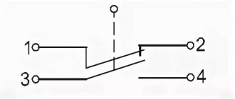
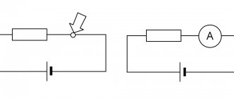
Switches are used to connect and disconnect electrical circuits. These products have two operating positions: “on” and “off”. The connection and disconnection of the circuit (closing and opening) is carried out by a movable contact, which is either permanently connected to one of the fixed contacts, and is connected to the other when the switch handle is set to the “on” position, or is made in the form of a jumper connecting the fixed contacts in the same position .
However, regardless of the design of the switching unit, the closing contact is depicted in the diagrams in the same way - in the form of an inclined line in a break in the electrical communication line (Fig. 1 on the left).
Unlike the make contact, which is always shown in the open position, the break contact is shown in the closed position. GOST 2.755-74 establishes three equal symbols for such a contact (Fig. 1 on the right), however, within the same circuit it is recommended to use one of them. N
The standard does not establish the direction of movement of the movable contact (both breaking and closing) from the initial position to the final position (except for the cases that will be discussed below).
Complex switches , designed for simultaneous switching of several electrical circuits, may contain several make or break contacts or combinations thereof.
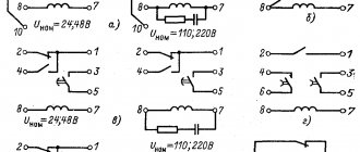
With a combined image of such a switch (i.e., in one place in the diagram), the lines indicating the moving contacts are drawn parallel to one another and connected by a mechanical connection symbol - two solid lines. The symbols of two such switches are shown in Fig. 2. The first of them (Fig. 2,a) contains two normally open contacts.
Rice. 2. Complex switches.
They can turn on (close) two electrical circuits, for example, both power supply wires of a device or one wire in the power supply circuits of two devices at once. Using the second switch (Fig. 2.6), you can, for example, turn on the power to the measuring device and at the same time open the sensitive dial current meter.
If for some reason the contact groups of a complex switch have to be depicted in different parts of the circuit, each of the symbols of the moving contacts is provided with a segment of a dashed line of mechanical connection, and the belonging to one product is indicated in the positional designation (Fig. 2, c, contact groups SA1.1 , SA1.2 and SA1.3 belong to switch SA1).
Basic UGO for single-line diagrams of electrical panels
| UGO | Name |
| Thermal relay | |
| Contactor contact | |
| Switch - load switch | |
| Automatic - circuit breaker | |
| Fuse | |
| Differential circuit breaker | |
| RCD | |
| Voltage transformer | |
| Current transformer | |
| Switch (load switch) with fuse | |
| Motor protection circuit breaker (with built-in thermal relay) | |
| A frequency converter | |
| Electricity meter | |
| Normally closed contact with reset button or other push-button switch, with reset and opening by means of a special actuator of the control element | |
| Normally closed contact with push-button switch, with reset and opening by retracting the control button | |
| Normally closed contact with push-button switch, reset and open by pressing the control button again | |
| Normally closed contact with push-button switch, with automatic reset and opening of the control element | |
| Delayed closing contact that initiates upon return and operation | |
| Delayed closing contact which only operates on return | |
| Delayed closing contact which is only initiated when triggered | |
| Delayed closing contact which is actuated by return and tripping | |
| Delayed closing contact which only operates on return | |
| Delayed closing contact that only switches when triggered | |
| Timing relay coil | |
| Photo relay coil | |
| Pulse relay coil | |
| General designation of a relay coil or contactor coil | |
| Indication lamp (light), lighting | |
| Motor drive | |
| Terminal (separable connection) | |
| Varistor, surge arrester (surge suppressor) | |
| Arrester | |
Socket (plug connection):
| |
| A heating element |
Laptop keyboard. Key assignment
Special or control keys
First of all, we will talk about the purpose of special (control) keys.
- Esc – Pressing this key cancels the action in the program. If you press the Esc key in the game, you will exit to the desktop.
- Ctrl – Is functional only when combined with other keys.
- Alt – Functional only when combined with other keys.
- Fn Lock – Present only on laptop and netbook keyboards. When Fn Lock is activated, the F1-F12 keys are activated.
- Windows (Win) – Key to open the main Start menu.
- Print Screen – Function of taking a screenshot of the visible part of the screen.
- Pause Break – Allows you to stop the current operation in the program. Pause the game.
- Scroll Lock – When activated, the mouse can work like a ball joystick. This way, you can scroll the page without scrolling the mouse wheel.
Number keys
- Num Lock – Key to activate the right layout of numbers and symbols.
Alphanumeric keys
- Caps Lock – Activates the caps function.
- Shift – Temporarily activates the capitalization function.
- Tab – In text editors, a new row or column is created.
- Backspace – Key for deleting characters, numbers, and also for canceling an action.
- Enter – Key to confirm actions.
Keys for moving
- Insert (Ins) – The key performs the function of replacing text when typing.
- Delete – Function key that allows you to delete text and files.
- Home – When typing, pressing the key can move the cursor to the beginning of the text.
- End – When typing, pressing the key can move the cursor to the end of the text.
- PgUp – Key for scrolling up a page in a browser and text editor.
- PgDn – Key for scrolling down a page in a browser and text editor.
Now that we have described each key, we need to tell you how the keys work in combination with others.
Functional shortcuts for the Alt key
- Alt + F4 – Close a program or game window.
- Alt + Prtsc Sysrq – Create a snapshot of the active window.
- Alt + Backspace – Cancel the previous action/operation.
- Alt + Tab – Switch between windows.
- Alt + Shift – Switch keyboard layout language.
Functional combinations for the Ctrl key
- Ctrl + End – Scrolls the page down.
- Ctrl + Home – Scroll the page up.
- Ctrl + Alt and Del – Launch the Task Manager application.
- Ctrl + Arrows down, up, left, right – Arbitrarily move the cursor when typing.
- Ctrl + Esc – Launch the Start window.
- Ctrl + O – Open a document in text editors (Word, Excel, etc.).
- Ctrl + W – Closing a document in text editors (Word, Excel, etc.).
- Ctrl + S – Saving documents in text editors (Word, Excel, etc.).
- Ctrl + P – Activate the function of printing documents in text editors (Word, Excel, etc.).
- Ctrl + A – Select all files and documents. In text editors – full text selection.
- Ctrl + C – Copy selected files and documents. In text editors – copying selected text.
- Ctrl + V – Pastes the copied text/file to the final location.
- Ctrl + Z – Cancel the previous action/operation.
- Ctrl + Shift – Switch keyboard layout language.
Functional shortcuts for the Shift key
- Shift + Down, Up, Left, Right Arrows – Select a character or letter.
- Shift + Del – Delete a file or document from the system.
Functional shortcuts for the Win key
- Win + D – Minimize all open windows.
- Win + R – Launch the Run utility.
- Win + E – Launch the Explorer application.
- Win + F – Launch a search in the browser, text editors.
- Win + Tab – Switch between program and application windows.
Letter designations in electrical diagrams
The standards for the letter designation of elements on electrical circuits are described in the GOST 2.710-81 standard with the text title “ESKD. Alphanumeric designations in electrical circuits." The mark for automatic devices and RCDs is not indicated here, which is prescribed in clause 2.2.12 of this standard as a designation with multi-letter codes. The following letter codings are accepted for the main elements of electrical panels:
| Name | Designation |
| Automatic switch in the power circuit | QF |
| Automatic switch in the control circuit | SF |
| Automatic switch with differential protection or difavtomat | QFD |
| Switch or load switch | QS |
| RCD (residual current device) | QSD |
| Contactor | K.M. |
| Thermal relay | F, KK |
| Timing relay | KT |
| Voltage relay | KV |
| Impulse relay | KI |
| Photo relay | KL |
| Surge arrester, arrester | F.V. |
| fuse | F.U. |
| Voltage transformer | TV |
| Current transformer | T.A. |
| A frequency converter | UZ |
| Ammeter | PA |
| Wattmeter | PW |
| Frequency meter | PF |
| Voltmeter | PV |
| Active energy meter | P.I. |
| Reactive energy meter | PK |
| Heating element | E.K. |
| Photocell | B.L. |
| Lighting lamp | EL |
| Light bulb or light indicating device | H.L. |
| Plug or socket connector | XS |
| Switch or circuit breaker in control circuits | S.A. |
| Push-button switch in control circuits | S.B. |
| Terminals | XT |
Designation of measuring electrical instruments to characterize circuit parameters
| A heating element |
| UGO | Name |
| PF | Frequency meter |
| PW | Wattmeter |
| PV | Voltmeter |
| PA | Ammeter |
GOST 2.271-74 accepts the following designations in electrical panels for buses and wires:
Representation of electrical equipment on plans
Despite the fact that GOST 2.702-2011 and GOST 2.701-2008 take into account this type of electrical circuit as a “layout diagram” for the design of structures and buildings, one must be guided by the standards of GOST 21.210-2014, which indicate “SPDS.
Images on the plans of conventional graphic wiring and electrical equipment.” The document establishes UGO on plans for laying electrical networks of electrical equipment (lamps, switches, sockets, electrical panels, transformers), cable lines, busbars, tires.
The use of these symbols is used to draw up drawings of electric lighting, power electrical equipment, power supply and other plans. The use of these designations is also used in basic single-line diagrams of electrical panels.
Conventional graphic images of electrical equipment, electrical devices and electrical receivers
The contours of all depicted devices, depending on the information richness and complexity of the configuration, are taken in accordance with GOST 2.302 on the scale of the drawing according to the actual dimensions.
Conventional graphic designations of wiring lines and conductors
Conventional graphic images of tires and busbars
IMPORTANT: The design position of the busbar must exactly coincide on the diagram with the place of its attachment.
Conventional graphic images of boxes, cabinets, panels and consoles
Conventional graphic symbols of switches, switches
On the pages of documentation GOST 21.210-2014 there is no separate designation for push-button switches, dimmers (dimmers). In some schemes, according to clause 4.7. the normative act uses arbitrary designations.
Conventional graphic symbols of plug sockets
Conventional graphic symbols of lamps and spotlights
The updated version of GOST contains images of lamps with fluorescent and LED lamps.
Conventional graphic symbols of monitoring and control devices
Load control with one button without fixing
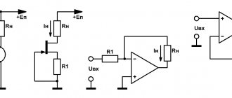
Sometimes there is a need to control a particular load with just one button. There are two types of buttons, with and without latching. If you use non-latching buttons, for example to turn on an LED, then when pressed the LED will light up and when released it will go out.
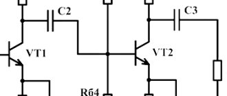
The above circuit is incredibly simple and consists of three transistors, two of which are of reverse conductivity. It works according to the following principle: when pressed for the first time, the LED will light up, and when pressed again, it will go out.
There are many areas of application for such a simple electronic button, from simple flashlights to powerful switching systems.
Main types of symbols according to GOST
Electrical diagrams belong to technical drawings and are one of their varieties. They display all the components of certain circuits, indicated by special symbols. They are divided into several main groups, including various types of consumers, current sources, control elements and conductors.
Their graphic representations are applied to the drawing, using lines of different thicknesses and ordinary geometric shapes. They can be square and rectangular, in the form of a circle or arc, triangle, simple line and dotted line, etc. All these symbols include not only graphics, but also symbols consisting of letters and numbers. Applied all together, they interact with each other according to the established system and are able to display any hardware and equipment, connecting lines with mechanics, electrical networks, all kinds of windings, switching means and other similar components.
The composition of the schematic diagrams can be supplemented by specially developed UGOs that explain the specifics of the action of certain components. As a living example, we can take the different types of contacts used for making, breaking and switching. The general symbolism provided by GOST corresponds to only one direction of operation of these devices - closing and opening a given circuit. All additional functionality is indicated by symbols on the moving contact part. Using this symbolism, the required element can be easily identified on any diagram - relays, buttons, contactors, starters, etc.
Some types of parts and components may appear in more than one appearance. This applies to transformer windings, switching contacts and other components that are used in these conditions. In the event that the standard list does not contain the required designation, it is compiled independently, based on the operating principle of the given element. As a basis, icons are used that are used to display similar equipment.
A huge number of graphic UGO icons and their combinations represent a detailed element base, indispensable when making all kinds of electrical drawings and diagrams. Images are drawn according to established standards, observing line width, dimensions and other parameters. All types of schemes are divided into several components. According to their purpose, they are single-line, installation and principle type.