The inrush current of a transformer is a short-term magnetizing current of a transformer, exceeding the rated load current, which occurs when the transformer (autotransformer) is switched on or when it is restored. At the same time, the inrush of the magnetizing current may differ from time to time on the same transformer, since the vector and magnitude of the voltage supplied to the transformer winding when the switching device is turned on matters.
The concept of magnetizing current
The sudden increase, that is, the inrush of the magnetizing current (BCT), is explained by the saturation of the core by magnetic induction. Transformers are dynamically resistant to surges due to the manufacture of windings taking into account large currents, as a rule, arising from short circuits. On average, the magnetizing current exceeds the rated value of the device by 6-8 times.
Rice. 1. Conditions for the appearance of BTN
In short circuit mode, the voltage of the power unit is characterized by an extreme decrease to zero, and after disconnecting the damage zone, it is established at the terminals of the device in an abrupt manner.
The restoration of the magnetic flux occurs unevenly and not immediately, which causes the occurrence of a transient process, during which two fluxes are formed - a steady FU and a free FSV. To determine the total value, the formula is used:
FTO = FU + FSV
At the reference point, which characterizes the initial moment of time at t = 0, the FTO is also equal to zero, so the equality FSV = – FU seems fair. The signs of the polarity of magnetic fluxes coincide in the second half-cycle, and, accordingly, the resulting value reaches a peak maximum (FTmax).
Rice. 2. Magnetic fluxes in the core under load
Schematically, there is a lag of FU from UT by 90 degrees, which indicates the dependence of FSV and FTmax on the voltage phase. These values reach their highest values when turned on - at the moment UT passes through zero. If we do not take into account gradual attenuation, FTmax ≈ 2FU. But the peak flux value can be higher when there is residual magnetization Fost in the core thickness, which coincides in sign with FSV.
Then:
FTmax = (2FU + Fost)> 2FU
The core is saturated at flux values close to 2FU, causing a sharp surge in In. The magnetizing current is generated only in the winding of the circuit to which voltage is applied when turned on. It is converted through a protective device and enters the relay, causing it to operate subject to the inequality Iam > Is.z..
Installation, connection, dangerous factors
If the insulation of the windings breaks down, the possibility of electric shock arises, but the risk is prevented by grounding the output (indicated on the housing) of the secondary.
The currents at the terminals of the secondary coil I1 and I2 are polar; they must be permanently connected to the load. Energy flowing through the primary circuit with significant potential (S=UI). In the other, a transformation occurs, and when it breaks, the tension drops there. The potential of open ends when energy flows is high, which poses a significant danger.
For the reasons described above, all secondary CT circuits are assembled especially carefully and reliably; shunt short circuits are always installed on them and cores taken out of operation.
How is the TT connected?
There are several schemes for protective products. Let's consider connecting a CT to three-phase voltage.
Full star:
- the most common, protection of single- and multi-phase systems against short circuit;
- three CTs are connected into a star.
If the current is below the settings on relays KA1–KA3, then this is a normal situation, the protection is not activated. The current at K0 is the sum of all 3 phases. As the values in one of them increase, the current in the CT also increases. The relay will operate in case of short circuit and when the load is exceeded.
Partial star:
- protection against phase-to-phase faults to create circuits with a neutral grounded;
- for low power receivers with other protection options.
Delta and star circuit - for differential protection.
A circuit without de-energizing during a ground fault is used, but rarely for the same reason. For protection against short circuits between phases and surges in one of them.
TTIs are connected by simple serial connection of the primary turns of the product.
Installation
Installation of current transformers:
- Inspection of the device, checking the insulation (must be above 1 kOhm per 1 V);
- Switch off the power supply;
- Make sure there is no power, fix the grounding.
- Marking, installation of fasteners. It is prohibited to place the transformer close to the power plant (minimum gap - 10 cm).
- Signs and fences are put up.
- The primary turns are connected in series, but with a load on the secondary ones. If it is not possible to connect the meter, then its contacts are closed so that there is no high power on it, which will damage it.
The CT does not allow idle operation; its mode is close to short circuit: the secondary turns are necessarily closed when the device is connected to the measured current. Otherwise, overheating occurs, damaging the insulation. Before disconnecting the meters, first short-circuit the coils. Some models have terminals and jumpers for this purpose.
Calculation
The current transformer can be calculated using online calculators and selected according to its nominal value (for example, for 10 kV). But these are too simplified tools. Calculus and parameters to choose from is an extremely broad topic, so let's cover the basics.
Accuracy is extremely important, so careful calculations by specialists will be required. You need to know many specific nuances, for example:
- for different connection schemes and types of short circuit, there are different formulas for determining resistance;
- check the primary current for thermal and electrodynamic resistance;
- There are some nuances for CTs, for relay protection and for accounting purposes and measurements.
Rules for choosing a current transformer in general terms:
- the rated operating voltage of the CT must exceed or be compared with the rated power plant (standard values 0.66, 3, 6, 10, 15, 20, 24, 27, 35, 110, 150, 220, 330, 750 kV). If the equipment being serviced has 10 kV, then the product must be designed for this indicator;
- the primary current of the CT is greater than the rated current of the power plant, but taking into account the overload capacity;
- CTs are assessed by the rated power of the secondary load, which must exceed its calculated value. (Snom>=Sload);
- evaluate the dimensions and location for installation, rated loads (there is a table), time to failure, service life, accuracy class.
Check after calculation
Rules:
- After calculation, the CT is checked by loading at max. and min. values of loads flowing through it;
- according to clause 1.5. 17 PUE at max. connected load, the current in the secondary coil is at least 40% of the meter rating, at min. — not less than 5%;
- Max. the load should be from 40%, and min. - from 5%, and in any case it should not exceed 100%, otherwise the transformer will be overloaded;
- if the calculated values of max./min. loads are less than 40% and 5%, respectively, then you need to select a product with a lower rating, and if this cannot be done according to the parameters of max. load, it is necessary to provide for the installation of two meters - for max. and min. loads.
Why does the surge occur when turned on?
A short-term jump is characterized by an inrush of the magnetizing current of the transformer (BTC). Its values on the same device may differ in value for different switching ons. The reason for the formation of BTN in power devices is a sudden change in the magnetizing voltage level. In addition to the load transferred to the winding, the surge can be caused by other reasons:
- external short circuit (SC);
- restoration of voltage in the circuit;
- short circuit transformation;
- non-synchronous connection of the generator.
The magnetizing current introduces an imbalance at the transformer terminals. The device protection perceives the BTN as a differential current. But in order for it to correctly fulfill its purpose, the system must function effectively and be configured taking into account the BTN by including auxiliary devices such as intermediate transformers in the circuit.
To prevent surges from affecting the operational life of the unit, it is undesirable to allow the transformer to turn off as a result of surges.
When the winding is turned on at full load, due to asynchronous power distribution and transient wave processes, a high overvoltage occurs, which can cause an internal short circuit.
Important! Overvoltages due to BTN are safe only if the differential protection of the system is properly organized.
Correctness of loss measurement
Loss measurements are carried out only if it is mandatory to use an installation that has high power ratings. At this time, it is allowed to use a lower voltage for calculations, which is connected to the primary circuit through a measuring device such as a wattmeter. This type of measurement is called the direct method.
If we take into account the provided indicators of such measuring equipment as a voltmeter or ammeter, it will be necessary to additionally multiply their powers one by one. This method is also called indirect
When obtaining results using this method, it should be taken into account that the result may contain some errors. The reason for the distortion is that it is not possible to fully take into account the power factor
When this mode operates, an angle of ninety degrees is formed between them.
How the process works
When a load is applied, the magnetization of the device due to switching on is considered as a negative phenomenon that can provoke a BTN of maximum amplitude. When turned off, the magnetizing current is reduced to zero, and the magnetic induction is adjusted depending on the degree of magnetization of the steel core, as a result of which residual induction remains in the magnetic circuit.
If after a while the current-converting device is switched on again under a voltage subject to the sinusoidal law of change, the magnetic induction changes with a displacement of the residual value up to 90% of the nominal value. The result is a high magnetization amplitude and a change in the shape of the curve.
Rice. 3. Classic type BNT curve
The magnetizing current level decays within tenths of a second, but complete “smoothing” of the curve occurs within a few seconds, and under certain conditions – after a few minutes. The duration of attenuation of the aperiodic component of the BTN oscillogram is due to the high amplitude of the current at the initial (zero) moment of time and the content of various harmonics. The peak value depends on the load voltage and its parameters, as well as on the value and polarity of the residual magnetic flux in the core.
The peak current can be 10-15 times higher than the rated value for high-power units, and 20-25 times higher for devices with power (<50 kVA). The decay period ranges from a few milliseconds to seconds.
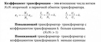
The importance of transformation ratio, accuracy class, error
Transformation coefficient (CT) - determines the proportionality of the transformation, is set during the design of the transformer, and must be checked upon release. In the diagram this is K1, determined by the ratio l1/l2 (two vectors).
The efficiency coefficients of the assembled products reflect the accuracy class. In actual operation, current values are not constant, so the coefficient is designated nominal. Example: 1000/5 - at 1 kA of operating current (primary), a load of 5 A is applied in the secondary circuit. It is based on the described values that the operating duration of this transformer current is calculated.
The CT error affects its accuracy class and is determined by the cross-section, the level of permeability of the magnetic circuit material, and the magnitude of the magnetic path.
An increase in load resistance in the secondary circuit, exceeding the capabilities of the CT (in this case increased voltage is generated there), provokes an insulation breakdown - the transformer fails and burns out
Therefore, it is important to select this parameter correctly. The maximum resistance is in the reference materials
Methods of blocking on the secondary winding
There are several ways to eliminate false positives on BTN. The effectiveness of the method of slowing down protection (disadvantage - loss of performance), braking, blocking, which did not give good results, was experimentally tested. The most rational methods of detuning from magnetizing currents are:
- Use of fast-saturating transformers.
- Adjustment of differential cutoff.
The methods have proven their effectiveness in practice, are distinguished by high reliability, simplicity and preservation of the most important protection parameter - speed.
Transformer no-load mode
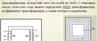
Idle circuit (XX) is the connection of a device when the rated alternating voltage is supplied to the primary winding, and the circuits of all secondary windings are open (no loads are connected).
In a voltage converter, the division of windings (coils) into primary and secondary is conditional. Any of them becomes primary when the original alternating voltage is applied to it. Others, in which EMF is induced, become, accordingly, secondary.
The idle test is carried out according to the scheme shown in the figure.
Consequently, any transformer, depending on the connection method, can be either a step-down or step-up transformer (except for an isolation transformer - with a transformation ratio equal to unity).
Since the secondary coil circuit is disconnected, there is no current in it (I2 = 0). I1 flows in the primary, forming the flux of the magnetic induction vector F1 in the magnetic circuit. The latter changes according to a sinusoidal law, but due to the magnetization reversal of the steel, it lags in phase from I1 by angle B (loss angle).
The following terminology applies:
- I1: transformer current XX;
- F1: working magnetic flux.
Under the influence of F1, an EMF arises in all coils:
- in primary – self-induction (E1);
- in secondary ones – mutual induction (E2).
The dependence of EMF on various parameters is determined by the formulas:
E1 = 4.44 * f * W1 * Ф1max *10 -8,
E2 = 4.44 * f * W2 * Ф1max * 10 -8, where
W1 and W2 - number of turns in the windings;
Ф1max is the magnitude of the magnetic flux at the maximum point.
Consequently, the numerical value of the EMF is directly dependent on the number of turns of the coil. From the ratio of the EMF in the primary and secondary windings, the main parameter of the device is determined - the transformation ratio (K): K = E1 / E2 = W1 / W2.
Compared to the primary coil, the secondary coil contains:
- in a step-up transformer – more (K is less than one);
- in the downward direction it is less (K is greater than one).
In addition to the working (main) magnetic flux Fr1 is formed in the installation. These are power lines that branch off from the working magnetic flux F1 in the core and close through the air around the turns of the coils. Like F1, Fr1 is variable, which means that, according to the law of electromagnetic induction, it induces self-inductive emf Ep1 in the primary winding.
E1 and Ep1 are always directed opposite the voltage U1 applied to the primary winding. By the nature of their effect on current, they are similar to a resistor, which is why they are designated by the term “inductive reactance” (X).
Capacitive and inductive reactance
Consequently, creating I1, the voltage U1 overcomes the active resistance R1 of the primary coil and both self-induction emfs. Mathematically it looks like this: U1 = I1 * R1 + (-E1) + (-Ep1).
The recording is made in vector form, therefore, the symbols “-” are placed before the designations of the self-induction EMF: they indicate the opposite direction of these vectors relative to the voltage U1. The no-load current I1 is not strictly sinusoidal.
It is distorted because it contains the so-called third harmonic component (THC), caused by eddy currents, hysteresis and magnetic saturation of the magnetic circuit. But with a certain degree of approximation, suitable for practical calculations, it can be replaced by an equivalent sinusoidal current with an equivalent effective value.
Loss table
Active power consumption is the losses of the XX transformer. Part of it is spent on heating the winding wire (I1 2 * R1). It is insignificant, since the resistance R1 of the wire is negligible and the current XX is also small - 3-10% of the nominal.
The main share is spent on eddy currents in the magnetic circuit and its magnetization reversal. These phenomena lead to heating of the magnetic circuit. F1, which causes the bulk of no-load losses, does not depend on the load current. Consequently, losses exist constantly and in any mode of operation of the device, including active (load).
Loss table XX:
| Rated power, kVA | Rated voltage HV/LV, kV | No-load losses, W |
| 250 | 10/0,4 | 730 |
| 315 | 10/0,4 | 360 |
| 400 | 10/0,4 | 1000 |
| 500 | 10/0,4 | 1150 |
| 630 | 10/0,4 | 1400 |
| 800 | 10/0,4 | 1800 |
| 1000 | 10/0,4 | 1950 |
| 1250 | 10/0,4 | 2300 |
| 1600 | 10/0,4 | 2750 |
| 2000 | 10/0,4 | 3200 |
| 2500 | 10/0,4 | 4200 |
Over time, losses increase due to the following changes in the magnetic circuit:
- the structure of steel changes;
- the insulation resistance between the plates drops;
- The insulation of the ties is broken, which leads to a short circuit between the plates.
Checking work
To check the device, turn it on in XX mode and perform the following measurements:
- a voltmeter measures the voltage supplied to the primary coil (U1);
- another voltmeter - voltage U2 at the terminals of the secondary winding. A device with a resistance that is quite high is used so that the current in the secondary winding remains zero;
- an ammeter is included in the primary winding circuit to determine the no-load current
- This also includes a wattmeter that measures power consumption.
After taking readings from the instruments, calculations are made:
- determine the transformation ratio: K = U1 / U2;
- XX losses are calculated using special formulas.
Using the data from the XX experiment in combination with the data from the short-circuited mode experiment, the efficiency of the device is determined.
How to remove background microphone noise on a laptop when power saving mode is activated
When saving mode is activated, the sound card does not have enough power. Therefore, interference appears. What to do? Press “Win+R”, enter the command “control”:
Further:
Click the "Create Schema" link.
Select High Performance mode.
Purpose of short circuit experience
The no-load open circuit test is performed to determine the core losses without current load.
The essence of the test is that the high voltage winding remains open while the output winding is connected to the consumer's normal network. The necessary measuring instruments are also connected there - a wattmeter, an ammeter and a voltmeter. As a result of this connection, the external voltage that is applied to the device slowly increases from zero to its nominal value.
The readings of all devices are recorded at the moment when the testing voltage reaches the required value in the output circuit. The physical essence of the measurement results is as follows:
- The ammeter shows the value of no-load current, the value of which is very small and hence the voltage drop can be neglected.
- The input power is indicated by a wattmeter. But the other side of the transformer is open, therefore, there is no output power, and the indicator on the wattmeter consists only of the values of power losses due to the degree of saturation of the core material and losses in the wires.
- A high-resistance voltmeter is connected through the external winding of the device. The high voltage winding is treated as an open circuit since the current through the voltmeter is negligible.
- The test results are highly accurate due to the low no-load current values and the absence of losses in the elements of the electrical circuit. Therefore, the wattmeter readings are guaranteed to determine the total losses in the core.
Pros and cons of such heating
Perhaps only user reviews can fully reveal all the advantages and disadvantages of this type of skirting board, but I will still try to list the main aspects that require attention. Among the undeniable advantages of the warm baseboard system is its unusual design, since it includes both a functional and an aesthetic side. If desired, the planks can be painted in any color, which removes any restrictions in creating interior solutions.
Continuing the topic of advantages, I would like to say that this heating method ensures uniform heating of the room, which minimizes the possibility of dampness and mold development. Also, dust does not actively rise into the air and drafts do not arise, and all this is due to the “thermal cushion”. This is especially true for apartments and houses where small children live. And one more plus, for which everyone loves Mr Tektum warm plinths so much, is the ease of installation, since even a person who has never held a construction tool in their hands can handle the design.
As with everything, the underfloor heating system also has its drawbacks. Unfortunately, the simplicity of the installation process does not always mean high operational efficiency. That is why it is still worth seeking advice from a specialist who will explain how to avoid disturbances in uniform heat transfer. The topic of the appearance of such a plinth comes up quite often, since construction stores offer various decorative overlays for it. It is better not to use them, as they affect the heat transfer process.
Next, I want to tell you about the disadvantages of specific types of heating systems. For example, a warm water baseboard can only be used in a clearly established temperature regime, as part of a central heating main. If the temperature drops, it will cause equipment failure and destruction. But an electric warm baseboard requires too much electricity, and in our time this entails serious financial costs. That is why not everyone can afford this type of device.
Methodology for calculating voltage, losses and short-circuit resistance
Calculations are carried out in the following sequence:
- Both components of the no-load current are determined:
Iμ = IsinΦ and Iw = IcosΦ.
- The values of reactive X and active R resistances in equivalent circuits that relate to the low-voltage winding are set:
X = V1 / Iμ and R = V1 / Iw.
Here V1 is the voltmeter reading on the low voltage winding.
- The final power value is calculated:
W1 = 2IμR and W2 = 2IwХ
W = (W21 + W22)0.5
This is explained by the fact that the voltage applied to produce the full load current, although small compared to the rated one, is still present on the windings.
- The value of equivalent resistance Zeq of the transformer is determined:
Zeq2 = R2 + X2.
The data obtained corresponds to those relating to the high voltage side of the transformer. Thus, as a result of the short-circuit test, the losses in the conductors a, as well as its approximate equivalent and reactance, are determined.
As a result of analyzing the information obtained, it is possible to determine the dependence of losses on the no-load current and voltage on the secondary winding.