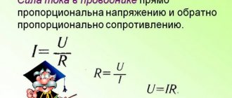
Today it is difficult to imagine life without light in the house, which creates an electric current in the lamp . Let's see how this happens?
Today there are several types of lighting devices (let's call lamps that way). The very first group of lamps worked without electricity. It was either a chemical reaction or fire. Then people learned about electricity and after much experimentation the incandescent lamp appeared. Structurally, the lamp consists of three required parts: a base, a bulb and a light source. In an incandescent lamp, a spiral of refractory metal acts as a light source. Remember, just recently we talked about the Joule-Lenz law, Ohm’s law and about the power of electric current? So, the light bulb very clearly demonstrates all these laws. The resistance of the incandescent light bulb spiral is selected in such a way that the current flowing through the spiral heats it up enough for the spiral to glow, but not be destroyed by exposure to high temperature. And the flask around the spiral is needed so that oxygen at high temperatures does not react with the spiral, causing severe oxidation and destruction. The flask is filled either with an inert gas, which in no way can react with the metal of the spiral, or, conversely, a vacuum is created in the flask.
In general, where there is high temperature, there are always large losses, low efficiency, short operating time and a bunch of other disadvantages, so people began to look for an alternative. Over time, various groups of lighting devices have appeared, which can be combined into two large groups: gas-discharge and LED.
Gas discharges use the ability of electric current to create an ion flow, glow discharge, plasma, etc. Depending on the design of such a lamp, the gas used and the design, they cause one or another effect of the electric current. And the work of the current ultimately leads to the glow of gas vapor.
LEDs have a slightly different operating principle. During the recombination process of a semiconductor junction, energy is released. Depending on the types of pn junction combination, this energy may be in the visible range. I'll tell you a little secret. A combination has not yet been found that would produce white LEDs, so white is obtained either using an ultraviolet LED with a phosphor coating, or a combination of red, blue and green.
This is how electric current works in a lamp in a nutshell. Of course, you can write a separate article for each type of lighting fixture. It's amazing how differently we can make the current illuminate our houses and streets at night.
Formula for voltage and power of a light bulb
This is the main formula of the article, the conclusion of which will be given below. The formula looks like this:
For any incandescent lamp there is a parameter that is stable over a wide range of electrical modes. This parameter is the ratio of the cube of voltage to the square of power.
The method of using the formula is simple.
We take a light bulb, read on the bulb or base the parameters for which it is designed - voltage and power, calculate the constant, then insert any arbitrary voltage into the formula and calculate the power that will be released by the light bulb.
Knowing the power, it is easy to calculate the current.
Knowing the current, it is easy to calculate the resistance of the filament.
So we will consider issues related to the correct use of the formula, as well as those restrictions that are inevitable due to the fact that there are simply no “absolute” formulas.
However, first a little “theory”...
Manufacturers
Many foreign and domestic companies produce incandescent lamps. Moreover, all products have their own markings. All lamps are marked with letters and numbers. There are four elements in total in the labeling. The first characterizes the physical and design features of the source. There is a vacuum lamp, gas-filled argon monospiral, argon double-spiral, double-spiral krypton, frosted and in a milk or opal flask. The second letter element indicates the functional purpose.
Note! There are automobile, railway, switchboard, searchlight and aircraft sources. The third element indicates the nominal type of voltage in volts, and the fourth element indicates the modification.
Popular brands
Basic "theoretical" premises
The formula was obtained under the assumption that in the metal (of which the filament consists) current and resistance have a single physical essence.
In a simplified form, it can be argued something like this.
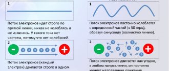
According to modern views, current represents the ordered movement of charge carriers. For a metal, these will be electrons.
It was assumed that the electrical resistance of the metal is determined by the CHAOTIC movement of the same electrons.
As the temperature of the filament increases, the chaotic movement of electrons increases, which ultimately leads to an increase in electrical resistance.
Again. Current and resistance in a filament are the same thing. The only difference is that current is an ordered movement under the influence of an electric field, and resistance is a chaotic movement of electrons.
Principle of operation
The source works by emitting wave radiation due to electronic molecular excitation and atoms, as well as due to thermal vibration of the filament molecular nucleus. As the temperature of the filament increases, the translational, vibrational and rotational energy of charged particles increases. As a result, the flux of radiation with average photon energy increases. The radiative wavelength moves into the short-wave infrared and long-wave visible regions. In the future, the body temperature will increase, providing energy that is sufficient to excite molecules and atoms and produce short-wave visible radiation. Therefore, the main factor that determines density with radiation wavelength is temperature.
You might be interested in this Features of the DNAT 250 lamp
Operating principle of incandescent lamps
A little “algebraic scholasticism”
Now that the “theory” is over (smiled), I will give algebraic calculations to derive the “main” formula.
The canonical notation of Ohm's law looks like this:
I * R = U
To harmonize the quantitative values, it is necessary to enter the appropriate proportionality coefficients, for the current component - Kt and for the resistive component - Kr:
The most general considerations lead to the idea that these coefficients should be mutually inverse quantities, which means:
In this case, multiplying the right and left sides in pairs (in the system of equations), we return to the original notation of Ohm’s law:
I * R = U
Final derivation of the formula
Let's take a closer look at the system of equations:
Let's square the first equation and multiply them in pairs.
On the left side we see the expression for power, and also remembering that the product of the coefficients is equal to one, we will finally rewrite it:
From here we get the expression for the current coefficient:
And for the resistive coefficient (they are reciprocal):
where Pnom and Unom are the rated power and voltage marked on the base or bulb of the lamp.
It remains to substitute these coefficient values into the “SPLIT” formula of Ohm’s Law, and we will obtain the final expressions for current and resistance.
Multiplying the last relation by Ux, we get:
In order not to bother yourself with these squares, cubes and roots, it is enough to remember the simple relationship that follows from the last relationship. By squaring the last ratio, we get a clear and understandable formula:
For any light bulb with a tungsten filament, the ratio of the cube of the voltage to the square of the power is a CONSTANT value.
The obtained relationships showed excellent agreement with practical results (measurements) in a wide range of voltage parameters and for very different types of incandescent lamps, ranging from indoor, automobile and ending with lamps for flashlights...
Lesson “Measuring power and current work in an electric lamp”
MUNICIPAL BUDGETARY EDUCATIONAL INSTITUTION
TOGLIATTI CITY DISTRICT
“School No. 43 named after Hero of the Soviet Union D.N. Golosova"
Methodological development of a physics lesson in 8th grade
Laboratory work “Measurement of power and current work in an electric lamp”
Physics teacher:
Ilyina Irina Nikolaevna
Tolyatti, 2022
Lesson type:
Technologies used:
Target:
Formed UUD:
lesson of developmental control and reflection
health, group, development of research skills
consolidate and deepen students’ theoretical and practical skills on the topic “Measurement of power and current work in an electric lamp”
subject:
learn to use the acquired skills of an experimenter in practice;
meta-subject:
draw up a plan and sequence of actions;
formulate conclusions that are adequate to the results obtained; personal:
independence in acquiring practical skills; careful handling of school equipment.
Lesson equipment ( set for laboratory
work ):
- power supply;
- low-voltage lamp on a stand;
- voltmeter;
- ammeter;
- key;
- connecting wires;
- stopwatch (or watch with a second hand);
“Electricity – how much does it cost?...”
During the classes:
I. _ Organizing time.
(The teacher and students greet each other, absentees are identified. The teacher gives safety instructions when working with electrical devices).
Safety instructions for laboratory
work
“Measuring power and current work in an electric lamp”
1.
Be attentive and disciplined, strictly follow the teacher’s instructions.
2 . Do not start work without the teacher's permission.
3.
Place instruments, materials, and equipment at your workplace in such a way as to prevent them from falling or tipping over.
4.
When conducting experiments, do not allow extreme loads on the measuring instruments.
5.
Monitor the serviceability of all fastenings in devices and fixtures.
6.
When assembling experimental setups, use wires with lugs with strong insulation without visible damage.
7.
When assembling the electrical circuit, avoid crossing wires.
8.
Connect the current source to the electrical circuit last.
9.
Do not touch live circuit elements that lack insulation.
10.
When finished, turn off the power source, and then disassemble the electrical circuit.
II. Performing laboratory work.
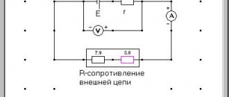
The teacher tells (and demonstrates) the procedure for performing laboratory work:
- assemble a circuit from a power source, a lamp, an ammeter and a key, connecting everything in series;
- connect a voltmeter in parallel with the lamp, close the switch and measure the voltage (U)
on the lamp;
- measure the current with an ammeter (I)
in a chain;
- draw a diagram of the assembled circuit in a notebook and write down instrument readings;
- calculate the current power in the lamp using the formula P=U
xI
; _ - calculate the work done by the current in the lamp using the formula A=U
x
I
x
t by
measuring the burning time
(t)
of the lamp in the circuit;
- record the results of measurements and calculations of physical quantities in the table:
Conductor
Voltage
U , V
Current
I , A
Time
t , sec
Current power P, W
Current work A, J
Bulb
- do conclusion
(write what you learned while doing the work).
Laboratory assistant
provides students with equipment (1 set per group).
Students
perform the practical part of the work (assemble an electrical circuit), measure voltage, current and time, calculate the power and work of the current in the lamp, and draw up the results.
Creative task No. 1
(5 min.)
(
for groups that completed the main task of laboratory work earlier than others
):
Take two identical light bulbs and connect them to the circuit once in series, and another time in parallel. Calculate the current power (P1 and P2) consumed by the light bulbs in both cases and explain the differences in the results obtained.
P 1
= U 1 x І 1 P 2 = U 2 x І 2
Output.
With a parallel connection, the power consumption is greater than with a serial connection (P 2 > P 1 ), because with a parallel connection, the circuit resistance decreases (R 2 < R 1 ), therefore, according to Ohm’s law for a section of the circuit (I = U / R), the current increases (I 2 > I 1 ) at a constant voltage at the poles of the current source.
III. Phys. pause.
Teacher:
“Now let’s do a warm-up to get some rest.”
Exercise 1 (for eyes)
- serves as a prevention of visual impairment:
- vertical eye movements up and down;
— horizontal right-left;
- rotation of the eyes clockwise and counterclockwise;
- eyelid massage.
Exercise 2
- necessary to improve brain function:
-pulling the earlobes from top to bottom;
-pulling the auricle upward;
-pulling the auricle outward;
- circular movements of the auricle clockwise and counterclockwise;
-cross movements – activates both hemispheres of the brain;
- shaking your head - improves mental activity and cerebral circulation.
IV. Creative task No. 2.
Teacher:
The work of electric current or the electricity consumed is determined using an electric meter , but you will have to “play” its role.
Find out (with the help of your parents) the rated power of any 3 electrical appliances in the apartment and their approximate operating time during the day (and month).
Calculate the cost of the electricity they consumed per month (following the Example
).
(To complete creative task No. 2
The teacher informs the students
the current
(at the time of completing the task)
tariff for 1 kWh of electricity)
.
Example.
(with teacher's comments, 1 student solves on the board).
The power of an electric iron is 0.6 kW.
Use the iron daily for 20 minutes. Calculate the current work for one month (30 days) and the cost of consumed electricity at a tariff of 2.69 rubles per 1 kWh. Given:
Solution:
P = 0.6 kW. A = P x t
t = 20 min = 1/3 hour x 30 days. = 10 o'clock A = 0.6 kW x 10 hours. = 6 kWh
Tariff = 2.69 rub/kWh Cost = A x tariff =
=6 kWh x 2.69 RUR/kWh = 16.14 RUR
A - ? Price - ?
Answer:
A = 6 kWh, cost = 16.14 rubles.
Teacher's comment:
As can be seen from the Example , the cost of electricity consumed by one household electrical appliance is low.
But if you remember how many household appliances there are in our apartments, it turns out that “electricity is not cheap,” and we need to try to save the family budget by promptly turning off electrical appliances that are not currently in use, and use energy-saving lighting bulbs that consume much less power than traditional ones incandescent lamps. V. Summing up the lesson.
Students:
- Present the results of work in groups (evaluation of work and assignment of marks is carried out after checking the notebooks with completed laboratory work).
- Answer the questions (reflection):
Continue the sentence:
- In this lesson I learned...
- Today I learned...
- Most of all I liked …
- The biggest problem I had was...
VI. Homework.
- Repeat §§ 50-52.
- P – 1182.
- Task p. 192 (calculate the work of current and the cost of electricity consumed per month by 3 household electrical appliances).
Literature
- Peryshkin A.V. Physics.8th grade: textbook / A.V. Peryshkin M.: Bustard, 2016. – 238, [2] p. : ill.
- Peryshkin A.V. Collection of problems in physics: grades 7-9: to textbooks by A.V. Peryshkina and others. “Physics. 7th grade”, “Physics. 8th grade”, “Physics. 9th grade." Federal State Educational Standard (for the new textbook) / A.V. Peryshkin M.: Publishing house “Exam”, 2015. – 270, [2] p.
- Shlyk N.S. Lesson developments in physics: 8th grade. M.: VAKO, 2017. 272 p.
Some general considerations on the resistance of incandescent light bulbs
Of course, for small voltage values (when the applied voltage differs SIGNIFICANTLY from the nameplate voltage), our formulas will be “twisted”.
For example, when calculating the resistance of a 95W, 230V indoor incandescent light bulb connected to a 1 volt voltage source, the formula
gives a filament resistance value of 36.7171 ohms.
If we assume that we applied a voltage of 0.1 volts to the lamp, then the calculated filament resistance will be 11.611 ohms...
Intuition suggests that this is not quite the case, but rather not the case at all...
In the region of low voltages, the formula will steadily “lower” the value of the calculated resistance compared to the actual one, and the point here is this...
In the concept under consideration, it is implicitly assumed that the chaotic movement of electrons will “FREEZE” in the absence of an external applied voltage. However, it is obvious that the movement of electrons does not “freeze” even in the absence of an applied external voltage (if the lamp is simply lying on the table and is not turned on anywhere).
The chaotic movement of electrons has a THERMAL nature and is caused by the NATURAL TEMPERATURE of the filament.
This point is not taken into account by the formula, and direct measurement of the thread resistance with a device will inevitably show the difference between the measured resistance value and the calculated one.
Emission and efficiency of an incandescent light bulb
Before dealing with the question of the applicability of the formula for calculating “low voltage” modes, attention should be paid to one point.
The light bulb is an almost perfect converter of electrical power into radiant energy.
The fact that light bulb developers strive hard to increase the efficiency of the light bulb does not in any way affect this statement. An incandescent lamp is an ideal converter of electrical power into radiation.
The fact is that developers strive to increase the output of LIGHT energy, and it is in this sense that efficiency is calculated. The developer strives to increase the conversion factor of electrical power into LIGHT radiation, into radiation in the visible range.
This efficiency of the light bulb is really SMALL. However, the light bulb emits perfectly IN THE ENTIRE spectrum and very much in the infrared range, where our eyes cannot see.
To calculate purely electrical parameters, it is not at all important to us IN WHICH range the light bulb emits. It is only important for us to remember that the light bulb ALWAYS EMMITS if only some (even the smallest) voltage is applied to it. And it is important to remember that the supplied power is dissipated in the form of radiation.
How much electrical power is supplied to the lamp, it is SUCH power that will be dissipated in the form of radiation .
No one has canceled the law of conservation of energy, and no one has canceled the second law of thermodynamics either. This means that as much as has arrived, so much must leave. And it will disappear precisely in the form of radiation, because there is simply NO WHERE more energy can go – only into radiation. This is a very important circumstance.
Structurally, the filament is a thin tungsten wire with a diameter of about 50 microns and a length of about half a meter, rolled into a spiral of an intricate configuration.
The vacuum in the flask eliminates the possibility of convection heat transfer - ONLY THROUGH RADIATION.
Of course, some of the heat escapes through the antennae of the lamp on which the spiral is attached, but this is minuscule.
To visualize this smallness, we can draw an analogy.
Let me repeat, the tungsten thread itself is exactly the size of a hair from a first-grader’s braid, 50 cm long and 50 microns in diameter.
If you visually enlarge this hair... it’s as if we have wires with a diameter of 1 mm and a length of 10 meters! Common sense dictates that this wiring should NOT be cooled by heat exchange at the edges. Yes, something will be lost at the contact points, but the main power will be dissipated along the entire length of the wiring.
For the case of a spiral located in a vacuum, all the power will go into RADIATION and it doesn’t matter in what range of the spectrum...
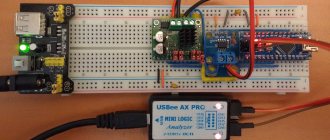
How is the luminous flux of an LED lamp measured?
LED bulbs
As I already said, the luminous flux of an LED lamp or any other light source can be measured in Lumens. On lamp packaging, Lumens are abbreviated as Lm or Lm. Before moving on to the calculations, it is important to understand what Lumen is. Let's imagine that our light bulb is a bag of sand from which sand is constantly pouring out; imagine that one lumen is one grain of sand. The number of lumens for our bag bulb will mean how many grains of sand will fall on one square meter of surface, for example, 900 lumens will mean that 900 grains of sand will fall on one square meter.
But we don’t have ordinary sand, but light, and it is scattered evenly over the entire surface, so if the luminous flux of a lamp is 900 lumens, and the area of the room is 3 square meters, then 300 lumens will fall per square meter.
And here we come to another very important parameter - the illumination of the room. Lumens characterize only the luminous flux of the lamp; if we continue our analogy, then the amount of sand that can spill out of the bag. But there is another parameter - this is the illumination of the room and it is measured in lux. Lux shows how many lumens will fall per square meter in a certain room. Designated Lk or Lx. If we said that our light source emits 900 Lumens, and the area is three square meters, then the illumination of our room will be 300 lux. For those who really love the formula 1 lux = 1 lumen / 1 square meter.
Got it? Now let's move on to the question of how to find out the lighting power of LED lamps.
An important experiment with measuring resistance with an Ohmmeter
Any, even the smallest current WILL have a thermal effect on the wiring, HEATING it...
By measuring the resistance of a light bulb with a tester, we... pass CURRENT through it. The current from the tester is small, but it IS. Therefore, by measuring the resistance of the thread, we HEAT the thread and, as a consequence of this, we change the value of the parameter by the very fact of measurement.
Roughly speaking, the tester ALSO LIES. The tester shows the NOT TRUE value of the helix resistance.
In order to verify this fact, you can do a simple experiment. This is available to anyone.
You can use the SAME tester to select two light bulbs with the same (close) values of “cold” filament resistance, and measure the resistance of the TWO light bulbs, first each separately, and then connected in series.
Repeated measurements show that the sum of the resistances measured separately DOES NOT COINCIDE with the total resistance of the series connection...
Again.
We measure the resistance of the bulbs separately.
We then measure the series resistance.
And we CONSTANTLY observe that the sum of the resistances measured “individually” turns out to be GREATER than the total resistance of the light bulbs connected in series.
The device is the same, the measurement range has not been switched, so methodological measurement errors are excluded.
And everything becomes CLEAR.
The series resistance of the two coils DECREASES the current from the tester and the filaments get less hot.
And when we measure the bulbs separately, the measuring current is greater and the readings of the device accordingly increase due to, even a small, INCREASE in the temperature of the filaments due to heating during the measurement process...
Previously (a quarter of a century ago, when digital testers were still exotic) it was impossible to catch this difference with a dial indicator. Nowadays, in any home there is a Chinese digital tester and anyone can do this simple experiment.
The difference in resistance is small, but the difference is OBVIOUS, which excludes even a hint of possible incorrectness of the experiment.
I connected the light bulbs, connected the tester and photographed the results of such experiments. The photographs clearly show that the tester shows a reduced resistance of the light bulbs connected in series.
Measuring the resistance of the first light bulb. 72 Ohm.
Measuring the resistance of the second light bulb. 65.2 ohms.
In the photographs for household light bulbs 60 Watt 220 Volt, the sum of resistances measured separately: 72.0 + 65.2 = 137.2 ohms.
However, by measuring resistance sequentially, the device “lowers” the reading to 136.8 ohms!
Measuring the resistance of two light bulbs connected in series. 136.8 Ohm
A similar picture is observed for garland light bulbs:
First light bulb
Second light bulb
Two light bulbs in series
Conclusion. The calculation formula shows an LOWER value of the resistance of the “cold” spiral.
Measurement by the tester shows HIGH resistance of the “cold” coil.
A natural thought arises - How scary it is to live!!! Who to believe?
\laugh\
Let's try to understand this issue...
Radiation power relative to the surrounding background
Let us estimate the lamp radiation power corresponding to the ambient background temperature.
It is known that the Stefan-Boltzmann constant σ = 5.670373·10-8, then the radiation power per square meter
Р = σ ST4
As an arbitrary estimate value, we will take the diameter of the spiral to be 40 microns and the length to be 50 cm. The normal temperature is 293K (20C). Substituting these data into the Stefan-Boltzmann formula, we obtain the radiation power at a temperature of 0.026258 Watt.
For fun, let's calculate the power at some different ambient temperatures:
Minus 40 (233K) 0.0105 Watt
Minus 20 (253K) 0.0146 Watt
Zero (273K) 0.0198 Watt
Plus 20 (293K) 0.026258 Watt (standard conditions)
Plus 40 (313K) 0.0342 Watt
For fun, you can give a calculation of the lamp radiation when the ambient temperature is 2300K:
P = 99.7 Watt.
Which generally agrees well with the real state of affairs - a lamp rated at 100 watts heats up to a temperature of 2300K.
We can say with a high degree of confidence that this spiral geometry corresponds to a “100-watt” light bulb rated at 220 volts.
Now let’s recalculate these power values to the “reduced” voltage. As if the ambient temperature corresponded to Absolute Zero, and some voltage was applied to the lamp, heating the coil.
To recalculate, we use the resulting relationship that voltage and power correspond to powers of “three” and “two”.
| tempera, K | voltage, V |
| 233 | 0,489665457 |
| 253 | 0,609918399 |
| 273 | 0,747109176 |
| 293 | 0,902119352 |
| 313 | 1,075809178 |
The table shows that the “current” power of the light bulb at a voltage of 0.902...Volt heats the coil to a temperature of 293K. Likewise, “current” power at a voltage of 1.0758 Volts will heat the coil to a temperature of 313K (20 degrees higher).
I repeat once again, this is provided that the ambient temperature is equal to Absolute Zero.
Conclusion . A very small change in voltage has a significant effect on the temperature of the filament. They changed the voltage by some seventeen hundredths of a Volt (1.0758 – 0.902 = 0.1738) and the temperature increased by 20 degrees.
These calculations are very arbitrary, but they can be used as ESTIMATED values.
The assessment is naturally very rough, because the Stefan-Boltzmann law describes the radiation of an “ideal” emitter - an absolutely black body (BLB), and the spiral is very different from the BLB, but, nevertheless, we obtained a very plausible “number”...
From the Excel plate it can be seen that even at a lamp voltage of 1 volt, the temperature of the coil will be 40 degrees Celsius. Let's do more, there will be more.
The natural conclusion is that at a voltage of 10-15 volts the thread will be quite hot, although this will not be visible visually.
To the eye, the thread will appear “BLACK” (cold) up to temperatures of 600 degrees (the beginning of radiation in the visible range).
Those who want to “drive the numbers” can do this on their own using the Stefan-Boltzmann formula.
The results will be conditional, due to the fact that (as mentioned above) the spiral has some albedo and does not correspond to the black body emitter, BUT(!) the temperature assessment will be quite reliable...
I repeat - it is ASSESSMENT. The filament begins to glow at about 20 volts.
Additionally, I would like to draw attention to the variation in the parameters of the light bulbs.
In the photo with the tester, the small light bulbs (garland) were selected and calibrated by me very carefully. For various measurement purposes and experiments. That’s why they show the same resistance, which is called “bullet to bullet.”
But the large light bulbs, I just brought them from the store, without selecting them according to parameters, and it is clearly visible that the spread of store-bought light bulbs is observed in a very wide range. Up to 10%.
This circumstance additionally indicates that the calculation errors turn out to be LESS than the actual spread of light bulbs.
Efficiency of an electrical appliance
As you know, ideal machines and mechanisms do not exist (that is, those that would completely convert one type of energy into another or generate energy). During operation of the device, part of the expended energy is necessarily spent on overcoming unwanted resistance forces or is simply “dissipated” into the environment. Thus, only part of the energy we expend goes to perform useful work, for which the device was created.
A physical quantity that shows what part of the useful work is expended is called the efficiency factor (hereinafter referred to as efficiency).
In other words, efficiency shows how efficiently the work expended is used when it is performed, for example, by an electrical appliance.
Efficiency (denoted by the Greek letter η (“this”)) is a physical quantity that characterizes the efficiency of an electrical device and shows what part of the useful work is expended.
Efficiency is determined (as in mechanics) by the formula:
η = AP/AZ 100%
If the power of the electric current is known, the formulas for determining the CFC will look like this:
η = PP/PЗ 100%
Before determining the efficiency of some device, it is necessary to determine what is useful work (what the device is designed to do) and what is expended work (the work being done or how much energy is expended to do useful work).
Some additional formulas
Above, I derived the formula that for any light bulb the ratio of the cube of the voltage to the square of the power is a constant value.
Purely for the sake of convenience, I propose to represent this constant in the form of a square of some value. Let's call it parameter S and rewrite the main formula
The advantages of the proposed method can be seen in this aspect. Since the parameter S turns out to be unchanged over a wide voltage range, it becomes possible to calculate circuits of light bulbs combined in an arbitrary manner.
For this, a number of formulas that can be easily derived independently will be useful.
For series and parallel resistance, you can use the formulas:
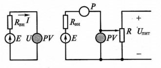
Circuit with ballast resistance
For the case when the lamp is connected in series with a ballast resistor, to calculate the voltage across it, it is necessary to solve a simple quadratic equation of the following form:
U + (Rresist / Slamp) * root(U) = U power.
Derivation of the formula with ballast resistance
The figure shows the procedure for deriving the formula for the case when the lamp is connected in series with a ballast resistor. The current through the lamp and through the resistance is the same.
The expressions for the currents are equal. Small algebraic transformations. And we get the final square equation with respect to the unknown Us.
From the figure it is clear that Us is the voltage across the lamp.
From the Blog Administrator.
This article is participating in the Summer 2022 Article Competition. Summing up (tentatively) in June 2022. Subscribe to receive new articles and join the VK group, there is always more news there than on the blog!
Lesson Plan
| Lesson steps | Time, min | Techniques and methods |
| I. Organizational moment, communication of the lesson plan. | 2 minutes | Teacher information. |
| II. Instruction on safety rules. | 2 minutes | Teacher information. |
| III. Performing laboratory work. | 25 min | Information from the teacher, practical activities of students. |
| IV. Phys. pause | 2 minutes | Warm-up |
| V. Calculation of the cost of electricity (creative task No. 2). | 7 min | Solution of the calculation problem. |
| VI. Summing up the lesson. | 5 minutes | Student reflection. |
| VII. Homework | 2 minutes | Teacher's message. |