Using iron filings to detect magnetic field
A magnetic field arises around conductors through which current flows. There are many ways to detect it, some of which we discussed in the last lesson.
Now we will look at another method - using small iron filings.
Why can iron filings be used to study the magnetic field? The answer is very simple: these small pieces of iron, once in a magnetic field, become magnetized - they become small magnetic needles .
Oersted's experiment has already shown us that the magnetic needle deviates from its original position when there is a nearby conductor through which current flows. Now we will have not one such arrow, but a large number of them. We can observe how the axis of each such arrow will be established under the action of magnetic field forces.
Ampere force: calculation options
Before formulating this value, it is necessary to understand what the concept of force is in physics. It is called a quantity in physics, which is a measure of the influence of all surrounding bodies on the object in question. Typically, any force is denoted by the English letter F, from the Latin fortis, which means strong.
The elementary Ampere force is calculated using the formula :
where dl is part of the length of the conductor, B is the induction of the magnetic circuit, I is the current strength.
The Ampere force is also calculated using the formula:
where J is the direction of current density, dv is the volume element of the conductor.
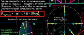
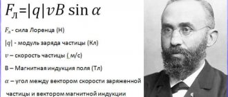
The formulation for calculating the Ampere force modulus, according to the literature, is as follows: this indicator directly depends on the current strength, the length of the conductor, the sine formed between this vector and the conductor itself, the angle, and the value of the magnetic circuit vector in the module. It is called the Ampere force module. The formula of this law is mathematically constructed as follows:
where B is the induction modulus of the magnetic circuit, I is the current strength, l is the length of the conductor, α is the angle formed. The maximum value will be at their perpendicular intersection.
The indicator is measured in newton x (symbol - N) or
. It is a vector quantity and depends on the induction vector and current.
There are other formulas for calculating the Ampere force. But in practice they are rarely used and difficult to understand.
Determining the shape of the magnetic field
What does a magnetic field “look” like? Let's do a simple experiment (Figure 1).
We have a straight conductor carrying current. Let's make a hole in a sheet of cardboard and thread our conductor through it. Place a thin layer of iron filings on the cardboard and turn on the current.
What will we see? How are the iron filings now located in a direct current magnetic field?
Figure 1. Arrangement of iron filings in a direct current magnetic field
Under the influence of a magnetic field, the sawdust will take an interesting position. They no longer lie randomly on a sheet of cardboard, but are located around the conductor in concentric circles.
Magnetic field lines
To describe the magnetic field and the circles of iron filings it creates, we will introduce a new definition - magnetic lines .
Magnetic field lines are the lines along which the axes of small magnetic needles are located in the magnetic field.
That is, if we connect the sawdust that formed one of the circles with an imaginary line, we will get a circle with a conductor in the center (Figure 2).
Figure 2. Direct current magnetic field lines
Please note that the arrows not only line up along these lines, but are also all oriented in the same direction along this circle. To make it easier to evaluate this, ordinary magnetic needles can be placed next to the conductor, as in Figure 2.
They are located on the magnetic field line, pointing one pole in one direction . Here we are not saying that they point to the right or to the left. They unfold with one pole, as if in one direction of movement around the circle.
Magnetic flux
Flat outline. The phenomenon of electromagnetic induction
As has already been mentioned many times, a magnetic field is generated by an electric current. Then is it possible that a situation where, on the contrary, a magnetic field will generate an electric current?
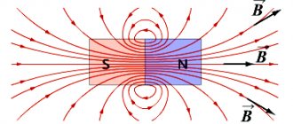
It has been established from experiments that a magnetic field can indeed generate a current. One of the simplest experiments to prove this is as follows: a closed flat circuit (all points of which lie in the same plane) of current-conducting material is connected to an ammeter (to record the current) and then brought into the area of a U-shaped magnet (see Fig. Figure 11).
Figure 11 – Conducting circuit in a magnetic field (K - circuit, A - ammeter)
During this experiment it was found out:
- the circuit is introduced into the field (during movement) - the ammeter records the current;
- the circuit rests inside the magnet - the ammeter needle is at zero;
- the circuit is removed from the magnet area - there is current;
- change the position of the circuit (rotate it around the diameter) - there is current.
What changed during the experiment? Judging by the figure, it is clear that the number of magnetic lines crossing the contour has changed (they are depicted with downward arrows). In the language of physics they say that the magnetic flux (F) penetrating the closed circuit has changed.
Magnetic flux is designated by the letter F and is measured in Webers.
[F] = 1 Wb.
It is directly proportional to the number of magnetic field lines crossing the plane bounded by the contour.
If a ring of a larger radius was used in the experiment, a larger flux would penetrate it (a larger area of the circuit could capture more magnetic lines). The field between the arms of a U-shaped magnet is assumed to be uniform.
If you leave the circuit the same, but take a more powerful magnet, the flux Ф will also become greater (with a stronger field, the magnetic lines are drawn thicker).
If you rotate the contour along its diameter, the area with which it “captures” the magnetic lines will decrease, and therefore the magnetic flux will decrease.
It turns out that the flux Ф is greater, the greater the value of magnetic induction (B) and the area of the circuit. In addition, it depends on how the contour is located in the field.
The occurrence of a current in a closed circuit (made of a conductive material) when the magnetic flux F, penetrating the area limited by the circuit, changes, is called the phenomenon of electromagnetic induction. And the resulting current is inductive.
The English scientist M. Faraday studied this phenomenon in detail.
Direction of magnetic lines and shape of the magnetic field
It turns out that the use of sawdust gave us two new characteristics of the magnetic field: we see not only its shape using magnetic lines, but also notice that the lines themselves have a certain direction.
So, we can draw the following conclusions:
The magnetic lines of the current magnetic field are closed curves (concentric circles in the case of a direct current magnetic field) surrounding the conductor.
The direction indicated by the north pole of the magnetic needle at each point in the field is taken to be the direction of the magnetic field line.
Relationship between the directions of magnetic lines and the direction of electric current
Magnetic lines give us the opportunity to depict the magnetic field graphically.
At what distance from the conductor can we draw its magnetic lines? The answer is simple - for a graphic image we can use a scale that is convenient for us.
A magnetic field exists at all points in space surrounding a current-carrying conductor. This means that we can legally draw a magnetic line through any point.
Okay, but how to determine the direction of magnetic lines? Experiments show the following:
The direction of the magnetic lines of the magnetic field of the current is related to the direction of the current in the conductor.
Since magnetic lines lie in a plane perpendicular to the current-carrying conductor, it is customary to depict a cross-section of a conductor in drawings (a cross-section of a conductor). The direction of the current is conventionally indicated by a cross if the current is directed away from us, and a dot if the current is directed towards us (Figure 3).
Figure 3. Current direction symbols
Take a look at Figure 4, a. Current flows down the conductor. Magnetic needles are installed along magnetic lines. Their axes are oriented as shown in the figure.
Figure 4. Direction of magnetic lines when current moves down/away from us
A graphical representation of such a magnetic field is presented in Figure 4, b. The conductor carrying current is located perpendicular to the plane of the drawing, as if we were looking at it from above, and not from the side. We marked the direction of the current with a cross on the conductor itself (away from us), and indicated the direction of the magnetic lines (where the north poles of the magnetic needles point.
Now we’ll make sure that the current goes up, not down. What will we see? The magnetic needles are again located along the circle, but the orientation of their axes has changed (Figure 5, a). Now they have turned around by $180 \degree$ compared to the first situation, where the current was flowing down the conductor.
Figure 5. Direction of magnetic lines when current moves up/towards us
Figure 5, b shows a graphical representation of such a field. The fact that the current is directed towards us is conventionally indicated by a point on the conductor. The direction of the magnetic lines has changed to the opposite.
Such a simple experiment confirmed to us the fact that the direction of magnetic lines is related to the direction of the current.
General rules
There are several options for specifying the direction of a perpendicular segment to two source vectors and defining the orientation of the basis. There are such important areas in physics:
- body rotations around the center of movement;
- force vector of the magnetic field at a selected point.
The choice of the path of the axial value is conditional, but it occurs in the same way, so the sign remains constant in the final value. Rules and methods help maintain a single choice:
- The gimlet rule. The wire is placed in the hand, with four fingers clenched into a fist. The main finger, which is located vertically, will show the path of movement of charged electrons (current). The remaining fingers, which are placed parallel to each other, will determine the direction of movement of the electromagnetic lines.
- Right hand rule. When placing the cable under test in your hand, the clenched fingers show the path of the force field lines, and the thumb shows the direction of the current. When the conductor moves forward along the lines that determine the tension, their movement is directed towards the palm. The thumb extended perpendicularly coincides with the movement of the rod. If you open your fist, your straight fingers will determine the course of the induction current.
- Left hand rule. The hand is positioned so that four fingers indicate the direction of electron movement. The path of the induction lines is directed into the palm. The bent finger shows the effect of force on the wire. The law acts to deflect a conductor rod, to the right and left of which magnets are located, and it is under current.
Using these rules, the direction of the vector product and bases (or one of two interrelated concepts) is selected. The technique is used to determine the directions of the main quantities instead of using other methods, if you have an idea of the order of the factors in the corresponding formulas.
Methods for choosing a rule are combined to calculate the positive path of the product of vectors and a basis (coordinate system) in space. A basis is defined as a coordinated vector set, with any vector in space represented in a single version of the linear relationship of vectors from this package.
Gimlet rule and right hand rule
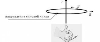
You can remember how the direction of the current in a conductor and the direction of magnetic lines relate, or you can use a simple method - the gimlet rule.
If you screw in a gimlet (screw, corkscrew) with your right hand with the tip in the direction of the current, then your thumb will turn in the direction of the magnetic lines.
You may find another interpretation of this mnemonic rule more convenient to use - the right-hand rule (Figure 6).
If you wrap your right hand around a straight conductor carrying current with your thumb out so that it coincides with the direction of the current, then your four fingers will show the direction of the magnetic lines.
Figure 6. Right-hand rule for a straight current-carrying conductor
Exercises
Exercise No. 1
Which pole will the magnetic needle turn towards the observer if the current in the conductor is directed from A to B (Figure 7)?
Will the answer change if the arrow is placed above the conductor? Figure 7. Magnetic needle located under the conductor
Using the knowledge gained, we can say that the magnetic needle pole towards us (Figure 8, a).
How did we determine this? If we draw a drawing (Figure 8, b) with point A towards us, then the current will flow from us. So we can, using the ready-made experimental results given above in this lesson, determine the direction of the magnetic field lines. The magnetic needle will turn its north pole in the direction of these lines, i.e. away from us.
Using the right-hand rule, we get the same result: if the thumb points in the direction of the current, then the four fingers point in the direction of the magnetic lines.
Figure 6. Orientation of a magnetic needle in a given direct current magnetic field
If we place the conductor under the magnetic needle, its position will change. It will turn its north pole towards us , because at this point the magnetic lines will also be directed towards us.
Exercise No. 2
There is a direct electrical wire located (walled up) in the wall.
How to find the location of the wire and the direction of the current in it without opening the wall? We can detect such a wire using a magnetic needle on a stand or a regular compass. When moving the compass along the wall (without turning it), you need to monitor the position of the magnetic needle. If it begins to deviate, it means that in this place it is affected by the magnetic field of a conductor with current - our wire is somewhere nearby.
To determine the direction of the current in this wire, let's look at where the north pole of the compass needle points. Its direction will coincide with the direction of the magnetic lines. If it turns to the right, then the current is directed upward, and if it turns to the left, then the current is directed downward.
A little history of magnetism
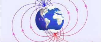
The study of the phenomenon of magnetism began many centuries ago, when back in the 6th century. BC. In ancient China, stones (rock) were discovered that attracted iron objects. In 1269, the French explorer Peter Peregrin placed small steel needles on the surface of a permanent spherical magnet and saw that they were not located chaotically, but along certain lines that intersected at two points, called “poles” by analogy with the geographic poles of the Earth. We can say that this was the first “visualization” of magnetic lines.
Only in 1845, the English physicist Michael Faraday formulated the concept of a “magnetic field” to understand the essence of magnetic phenomena. He believed that both electrical and magnetic interactions are carried out through invisible fields - electric and magnetic. The magnetic field is continuous in space and is capable of acting on moving charges.
In 1831, Michael Faraday discovered that an alternating magnetic field generates an electric field, and vice versa - a non-constant (time-varying) electric field creates a magnetic field. This phenomenon became known as Faraday's law of electromagnetic induction. The word induction is of Latin origin (induction) meaning “guidance, removal.”