4.4
Average rating: 4.4
Total ratings received: 62.
4.4
Average rating: 4.4
Total ratings received: 62.
The direction of the induction current arising in the process of the phenomenon of electromagnetic induction is not random. Let us consider the patterns by which this direction is determined.
Magnetic field of the coil
If current flows through the coil, a magnetic field appears around it. It can be seen by conducting an experiment with iron filings, similar to what we did for a straight conductor with current in the last lesson.
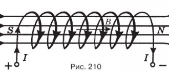
Figure 3 shows a schematic representation of magnetic lines for a current-carrying coil.
Figure 3. Magnetic lines of a coil with current
As you can see, magnetic lines are closed curves . It is generally accepted that they are directed from the north pole of the coil to the south .
Interaction of magnet and coil
If in Faraday's experiment a moving permanent magnet is connected to a dynamometer, then during movement the dynamometer will record the occurrence of additional force. This happens because the induction current arising in the coil, like any other current, leads to the appearance of its own magnetic field, which begins to interact with the magnetic field of the permanent magnet. The strength of such interaction will be recorded by a dynamometer.
When the magnet moves inside the coil, the force will be directed towards pushing the magnet out. However, if we begin to remove the magnet from the coil, this force, on the contrary, will begin to attract the magnet, preventing it from being removed from the coil. That is, the resulting magnetic field in the coil in these two cases has a different direction, which means that the current generating it also flows in different directions.
Right hand rule for current coil
You know that the direction of current and the direction of magnetic lines are related. Using the right-hand rule for a straight current-carrying conductor, we can find the direction of the current if we know the direction of the magnetic lines. Or, conversely, with a known direction of the current in the conductor, we can determine the direction of the magnetic lines.
For a coil with current, this rule also applies, but takes a slightly different form (Figure 4).
Right hand rule for a coil with current: if you take the coil in your right hand so that four fingers are facing in the direction of current flow, then the extended thumb will point to the north pole of the coil and coincide with the direction of the magnetic lines.
Figure 4. Right-hand rule for a current coil
Lenz's rule
The interaction of a current circuit and a magnetic field was studied by the Russian physicist E. Lenz.
Rice. 2. E. H. Lenz.
He established a rule that was later named after him:
The induction current arising in the circuit is always directed in such a way as to interfere with the cause that generated it.
And indeed, in accordance with this rule, when a magnet is introduced into a coil, the current arising in the coil creates a magnetic field that resists the introduction of the magnet. And vice versa - when a magnet is removed from the coil, an induced current appears in it in such a direction as to prevent the magnet from being removed.
Changing the magnetic action of the coil
Since current-carrying coils have two poles, they are often used in technology as magnets . Why not just use a regular magnet then?
The fact is that the magnetic action of the coil can be changed (strengthened or weakened). Now we will look at how this can be done.
Let's carry out a simple experiment (Figure 5). Let's add fine iron filings and turn on the current. The coil will begin to attract them.
Figure 5. Attraction of iron filings onto a current coil
And now, without changing the current strength, let's take a coil with a greater number of turns than the previous one. You will see that the amount of sawdust attracted has increased noticeably.
The greater the number of turns in it, the stronger the magnetic effect of a current-carrying coil.
a rheostat to our electrical circuit (Figure 6). It will allow you to change the current strength.
With the help of such changes in current strength, we will see that at different current values, the coil attracts different numbers of iron objects.
Figure 6. The effect of the magnetic field of the coil when the current changes.
As the current increases, the effect of the magnetic field of the current coil increases, and as the current decreases, it weakens.
Is it possible to increase the magnetic effect of a current-carrying coil without changing the number of turns and the current strength? Can! To do this, you need to insert an iron rod (Figure 7). Such rods are called cores.
Figure 7. Effect of the magnetic field of the coil when adding a core
Direction of induction current. Lenz's rule
“The art of the experimenter is
to be able to ask nature questions,
and understand her answers"
Michael Faraday
In this topic we will talk about how to determine the direction of the induction current. Consider Lenz's rule.
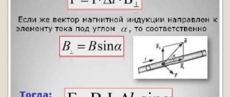
In the previous topic we talked about the phenomenon of electromagnetic induction and magnetic flux. Magnetic flux through a flat surface
is a scalar physical quantity, numerically equal to the product of the magnetic induction module by the surface area limited by the contour and by the cosine of the angle between the normal to the surface and the magnetic induction.
The phenomenon of electromagnetic induction
is that in a closed circuit, when the magnetic flux changes, an electric current arises in it, which we called induction.
Law of Electromagnetic Induction
states: the average value of the induced emf in a conducting circuit is proportional to the rate of change of the magnetic flux through the surface limited by the circuit.
The minus sign in the formula shows that the induced current counteracts the change in magnetic flux
.
Therefore, the induced emf and the rate of change of magnetic flux have different signs
.
Now is the time to talk about this in more detail and give a physical justification for this phenomenon.
As was shown in past experiments in a coil, when a magnet approaches or moves away from it, an induced current of different directions arises.
The induced current in the coil, like any other current, creates its own magnetic field, which interacts with the magnetic field of the permanent magnet. The task comes down to understanding the mechanism of this interaction.
To determine the direction of the magnetic field lines inside a coil with an induction current, we will use the gimlet rule
, which states that
if you rotate the head of the right screw according to the current in the turn, then the translational movement of the tip of the screw will indicate the direction of the magnetic field of the solenoid, and therefore its north pole.
If you bring a magnet closer to the coil, for example with the north pole, then an induced current will arise in it in such a direction that a magnetic pole of the same name will appear at the nearest end of the coil.
It can be seen from the figure that the magnetic induction vector of the permanent magnet field is directed downward, and the magnetic induction field vector of the resulting induction current is directed upward, since the magnetic induction field lines of the coil come out from the north pole. This means that in this case, i.e. with an increase in the magnetic flux passing through the coil, an induced current appears in it in such a direction that its magnetic field is directed towards the magnetic field generating this current.
It turns out that there are two magnets facing each other with like poles, and it is known that like poles repel each other. This leads to the fact that in this case the permanent magnet will always be repelled from the coil
.
If you remove the magnet from the coil, then at its nearest pole a magnetic pole will appear, opposite to the pole of the permanent magnet. It turns out that again the magnetic field of the induction current will prevent the change in the magnetic field that generates this induction current.
Those. there are two magnets facing each other with opposite poles, and it is known that opposite poles attract, which leads to the fact that a permanent magnet, in this case, will always be attracted to the coil
.
The same thing will happen if you change the pole of a magnet from north to south.
Thus, by observing the interaction between the poles of the coil and the magnet in all cases and comparing it with the direction of movement of the magnet, one can easily notice that the interaction between the poles always prevents the movement of the magnet
.
The famous Russian physicist, one of the founders of electrical engineering, Emilius Christianovich Lenz, came to similar conclusions in 1833.
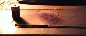
However, in his experiments, Lenz did not use a coil, but a device consisting of a narrow aluminum plate with aluminum rings at the ends. One ring was solid, and the other was split. This device was placed on a stand and could rotate freely around a vertical axis. Lenz took a strip magnet and inserted it into the rings.
When the magnet was brought to the split ring, no changes in the installation were observed. However, trying to insert the same magnet into a solid ring, Lenz observed how it began to “run away” from the magnet, while turning the entire plate. By removing the magnet from the ring, it returned to its original position. Lenz explained these phenomena as follows:
: when approaching the ring of a magnet, the field of which is non-uniform, the magnetic flux passing through the ring increases. In this case, an induction current arises in a solid ring, but in a ring with a cut, the current cannot circulate.
The repulsion of a solid ring shows that the induced current in it has such a direction that the induction lines of the magnetic field generated by the induced current are directed opposite to the induction lines of the external field of the magnet. Those. the ring and the magnet will face each other with like poles.
When the magnetic flux decreases (the magnet moves out), the induction current has such a direction in it that the induction lines of its magnetic field coincide in direction with the induction lines of the external magnetic field. Those. the ring and the magnet will face each other with opposite poles
.
Thus, by observing the interaction between the ring and the magnet in all cases and comparing it with the direction of movement of the magnet, one can see that the interaction between the poles always prevents the movement of the magnet.
Emilius Christianovich Lenz summarized the patterns he found and formulated a general rule. The connection he found is called his name, Lenz's rule.
.
It states that electromagnetic induction creates an induced current in a circuit in such a direction that the magnetic field it creates prevents a change in the magnetic flux that causes this current.
Using Lenz's rule, you can always determine the direction of the induction current. To do this you need:
– Find out the cause of the induction current (the magnetic flux through the circuit increases or decreases);
– Determine the direction of the magnetic induction vector of the inducing magnetic field;
– Find the direction of induction of the magnetic field of the induced current (if DF > 0, then ; DF < 0, then );
– Based on the direction of the magnetic induction vector of the induction current, determine, using the gimlet rule, the direction of the induction current.
Let us formulate the law of electromagnetic induction:
the average value of the induced emf in a conducting circuit is proportional to the rate of change of the magnetic flux through the surface limited by the circuit.
Having studied Lenz's rule, we can say that the minus sign in the mathematical notation of the law takes it into account.
According to this rule, if the magnetic flux increases (that is, the rate of change of the magnetic flux is greater than zero), then the induced emf will be negative and, conversely, if the magnetic flux decreases (when the rate of change is less than zero), the induced emf will be positive.
The induced current, and, consequently, the induced emf, occurs not only in linear conductors, but also in massive solid conductors placed in an alternating magnetic field. The only difference is that these currents are closed in the thickness of the conductor, and therefore they are called eddy currents, as well as Foucault currents,
which cause heating of the conductors. However, they also fully obey Lenz’s rule.
Main conclusions:
– The direction of the induction current is determined using the law of conservation of energy.
– Lenz's rule
: the induction current in all cases is directed in such a way that its magnetic field prevents the change in the magnetic flux that causes this induction current.
Electromagnet
Adding cores to current-carrying coils is a simple way to greatly enhance their magnetic effect. Therefore, such designs are widely used. They are called electromagnets .
An electromagnet is a coil with an iron core inside.
Electromagnets are a fundamental part of many devices. They have several extremely useful properties:
- They quickly demagnetize when the current is turned off
- During operation, you can change the current strength in the coil and in this way change the magnetic effect of the electromagnet
- Electromagnets are easily manufactured in a wide variety of sizes.
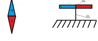
Rationale for Lenz's rule
To explain Lenz's rule, it is enough to recall the law of conservation of energy.
The current arising in the circuit, passing through the resistance of the circuit, does work, which is spent on heating the coil wire. The energy for this is precisely what arises when the magnet moves. And, since the magnet must perform positive mechanical work, the magnetic field of the coil must be directed against the field of the magnet itself, no matter in which direction it moves.
Only in this case will the magnet perform positive work, the energy of which will move charges inside the circuit, generating an induction current, and the induction current, in turn, will do work to heat the coil wire (and deflect the galvanometer needle).
Rice. 3. Direction of induction current.
Application of electromagnets
Let's look at a few examples of the use of electromagnets.
Figure 8 shows an arc-shaped electromagnet. It holds an iron plate (anchor) with a suspended weight.
Figure 8. Arc-shaped electromagnet
Such installations are widely used in factories for moving various metal products and collecting metal shavings.
Figure 9 shows a cross-section of a magnetic grain separator.
Figure 9. Magnetic grain separator
The principle of its operation is very simple. Very fine iron filings are added to the collected grain. They do not stick to smooth grains of cereals, but they do stick to grains of weeds.
From hopper 1, grains and sawdust are poured onto a rotating drum 2. Inside it there is a powerful electromagnet 5. It attracts iron filings, and with them weed grains. This is how the separator cleans the grain.
Electromagnets are also used in many other devices. We will look at some of them below in this lesson in the “Tasks” section.
Exercises
Exercise No. 1 You need to build an electromagnet, the lifting force of which can be adjusted without changing the design. How to do it?
The lifting force will depend on the magnetic action of the electromagnet. We know three ways to do this: change the number of turns, add a core, or change the current.
The first method is not suitable for us, since it involves changing the design. The second one is not suitable, since we already have a coil with an inserted core (electromagnet).
What remains is the change in current strength . In order for us to be able to do this, it is necessary to include a rheostat . By changing the current strength with its help, we will reduce or increase the magnetic effect of the electromagnet and change its lifting force.
Exercise No. 2 What needs to be done to change the magnetic poles of the coil with current to the opposite ones?
You already know that you can use the right hand rule to determine the poles of a coil. Using it, we clasp the coil so that our four fingers coincide with the direction of the current in the turns. Then our thumb points to the north pole of the coil.
This means that the direction of the current and the location of the poles of the coil are related to each other.
What can be done to make the North Pole appear on the other side? Reverse the direction of current .
Exercise No. 3 How to build a strong electromagnet if the designer is given the condition that the current in the electromagnet be relatively small?
If we cannot strengthen the magnetic effect of an electromagnet by increasing the current, then all that remains is to increase the number of turns in the coil .
We also cannot insert an additional iron core, since an electromagnet is already a coil with a core.
Exercise No. 4 The electromagnets used in the crane have enormous power. The electromagnets used to remove stray iron filings from the eyes are very weak. In what ways is this difference achieved?
To increase power, increase the number of turns in the coil, increase the current strength, and leave an iron core in the coil. To reduce power, you can reduce the number of turns, reduce the current, and remove the core.