Theory
An electromagnetic field is an analogue of mechanical force, manifested by the impact on moving carriers of electric charge, bodies with a magnetic moment.
It is characterized by the mechanical force that the field exerts on conductors or magnets. Experiments show that the magnetic field tries to orient the magnetic needle, to turn it relative to the plane of the coil, in a direction called the direction of the field. For a planet, it is taken as a line directed from geographic north to south. The electric field is characterized by a vector quantity E – intensity. To describe the magnetic effect, the value B is used, called magnetic induction.
To avoid confusion, the characteristics have different names.
Direction B is considered to be where the magnetic needle points relative to the coil with electric current. Its module is determined by the maximum value of the torque Mmax acting on the pointer. When the induction value is the same at each point in space, the field is called homogeneous; when its magnitude manifests itself in a substance to varying degrees, it is called inhomogeneous.
§16. Magnetic field and its characteristics and properties
Magnetic field and its characteristics.
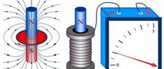
When electric current passes through a conductor, a magnetic field is formed around it. A magnetic field is a type of matter. It has energy, which manifests itself in the form of electromagnetic forces acting on individual moving electric charges (electrons and ions) and on their flows, i.e. electric current. Under the influence of electromagnetic forces, moving charged particles deviate from their original path in a direction perpendicular to the field (Fig. 34).
Rice. 34. Schemes of the action of a magnetic field on moving electric charges: positive ion (a) and electron (b).
A magnetic field is formed only around moving electric charges, and its action also extends only to moving charges. Magnetic and electric fields are inseparable and together form a single electromagnetic field. Any change in the electric field leads to the appearance of a magnetic field and, conversely, any change in the magnetic field is accompanied by the appearance of an electric field. The electromagnetic field propagates at the speed of light, i.e. 300,000 km/s.
Graphic representation of the magnetic field.
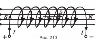
Graphically, the magnetic field is represented by magnetic lines of force, which are drawn so that the direction of the field line at each point of the field coincides with the direction of the field forces; magnetic field lines are always continuous and closed. The direction of the magnetic field at each point can be determined using a magnetic needle.
The north pole of the arrow is always set in the direction of the field forces. The end of a permanent magnet, from which the field lines emerge (Fig. 35, a), is considered to be the north pole, and the opposite end, into which the field lines enter, is the south pole (the field lines passing inside the magnet are not shown).
The distribution of field lines between the poles of a flat magnet can be detected using steel filings sprinkled on a sheet of paper placed on the poles (Fig. 35, b).
Rice. 35. Magnetic field created by a permanent magnet.
The magnetic field in the air gap between two parallel opposite poles of a permanent magnet is characterized by a uniform distribution of magnetic force lines (Fig. 36) (field lines passing inside the magnet are not shown).
Rice. 36. Uniform magnetic field between the poles of a permanent magnet.
For a more visual representation of the magnetic field, the field lines are placed less frequently or denser. In those places where the magnetic field is stronger, the field lines are located closer to each other, and in those places where it is weaker, they are further apart. The lines of force do not intersect anywhere.
In many cases, it is convenient to consider magnetic lines of force as some elastic stretched threads that tend to contract and also repel each other (have mutual lateral thrust). This mechanical concept of lines of force makes it possible to clearly explain the emergence of electromagnetic forces during the interaction of a magnetic field and a conductor with current, as well as two magnetic fields.
The main characteristics of a magnetic field are magnetic induction, magnetic flux, magnetic permeability and magnetic field strength.
Magnetic induction and magnetic flux.
The intensity of the magnetic field, i.e. its ability to produce work, is determined by a quantity called magnetic induction. The stronger the magnetic field created by a permanent magnet or electromagnet, the greater the induction it has. Magnetic induction B can be characterized by the density of magnetic field lines, i.e., the number of field lines passing through an area of 1 m2 or 1 cm2 located perpendicular to the magnetic field.
There are homogeneous and inhomogeneous magnetic fields. In a uniform magnetic field, the magnetic induction at each point in the field has the same value and direction. The field in the air gap between the opposite poles of a magnet or electromagnet (see Fig. 36) can be considered homogeneous at some distance from its edges. Magnetic flux Ф passing through any surface is determined by the total number of magnetic lines of force penetrating this surface, for example coil 1 (Fig. 37, a), therefore, in a uniform magnetic field
F = BS (40)
where S is the cross-sectional area of the surface through which the magnetic field lines pass. It follows that in such a field the magnetic induction is equal to the flux divided by the cross-sectional area S:
B = Ф /S (41)
If any surface is located obliquely with respect to the direction of the magnetic field lines (Fig. 37, b), then the flux penetrating it will be less than if it is perpendicular to its position, i.e. F2 will be less than F1.
In the SI system of units, magnetic flux is measured in webers (Wb), this unit has the dimension V*s (volt-second). Magnetic induction in SI units is measured in teslas (T); 1 T = 1 Wb/m2.
Rice. 37. Magnetic flux penetrating the coil when its positions are perpendicular (a) and inclined (b) relative to the direction of the magnetic lines of force.
Magnetic permeability.
Magnetic induction depends not only on the strength of the current passing through a straight conductor or coil, but also on the properties of the medium in which the magnetic field is created. The quantity characterizing the magnetic properties of a medium is the absolute magnetic permeability a. Its unit of measurement is henry per meter (1 H/m = 1 Ohm*s/m).
In a medium with greater magnetic permeability, an electric current of a certain strength creates a magnetic field with greater induction. It has been established that the magnetic permeability of air and all substances, with the exception of ferromagnetic materials (see § 18), has approximately the same value as the magnetic permeability of vacuum.
The absolute magnetic permeability of a vacuum is called the magnetic constant,
μa = 4π*10-7 H/m.
The magnetic permeability of ferromagnetic materials is thousands and even tens of thousands of times greater than the magnetic permeability of non-ferromagnetic substances. The ratio of the magnetic permeability μа of any substance to the magnetic permeability of vacuum μо is called relative magnetic permeability:
μ = μa/μo (42)
Magnetic field strength. The intensity And does not depend on the magnetic properties of the medium, but takes into account the influence of the current strength and the shape of the conductors on the intensity of the magnetic field at a given point in space. Magnetic induction and tension are related by the relation
H = B/μа = B/(μ*μо) (43)
Consequently, in a medium with constant magnetic permeability, the magnetic field induction is proportional to its strength. Magnetic field strength is measured in amperes per meter (A/m) or amperes per centimeter (A/cm).
Physical meaning of magnetic induction
Before moving on to the consideration of the magnetic induction formula, it is necessary to find out what explains the occurrence of the phenomenon itself in the system. The solenoid is not a flat element and includes a spiral of conductor (metal). In the absence of magnetic phenomena affecting it, the electric charges located in the crystal lattice of the spiral material behave statically. When a permanent magnetic element moves in the solenoid, forming a field, charged particles also move under its influence, then an electric current appears in the inductive element, the strength of which is determined by the characteristics of the magnetic and spiral element and how quickly the movement occurs.
Important! Fields having the same orientation are summed up to form a common field. When the movement of charged particles in the solenoid stops, the core ceases to exhibit magnetic characteristics if it is made of soft metal (this rule does not apply to steel products).
Lorentz force
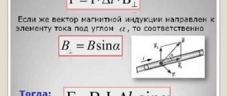
When a certain section of the wire through which electric current flows is located in field space, a force from the field acts on the moving charges. It is called the Lorentz force, after the name of the scientist who first discovered this phenomenon. Its value is influenced by the magnitude of current, induction and angle between the vectors of these two quantities.
Important! The maximum value of the Lorentz force is achieved when the conductor element forms a right angle with the field. When the directions of the field and current are parallel to each other, the force in question is absent.
To find out the vector of this force, you can use the right-hand rule. The index finger must be firmly fixed in a position showing the MF vector, and the thumb must be moved in the direction of the current movement. In this position, the middle finger, when pulled at a right angle to the hand, will point in the direction of application of the Lorentz force.
Direction of Lorentz force
To calculate the value of this quantity for a certain charge moving perpendicular to the field, use the expression:
F=B*q*v (here v is the speed of the charge).
When there is an angle between the directions, the formula takes the form:
F=B*q*v*sin α.
If you need to calculate the induction in a circuit placed in a uniform field, use the equality:
B=M(S*I),
where M is the moment of ampere force, and S is the surface area of the contour element.
Relationship between magnetic field strength and magnetic induction
General view of the magnetic field strength formula:
Н = I/(2*π*r).
Here H is the calculated value, I is the flowing current, r is the distance to the point whose field characteristic needs to be assessed. The unit of measurement of voltage looks like a quotient of the units in which current and distance are measured: ampere and meter (A/m).
For a solenoid containing n turns and having a length L , the expression will apply:
H = I*n/L.
Under vacuum conditions, the relationship between tension and induction values can be described as follows:
B = μ0*H,
where μ0 is a constant equal to 1.256*10-6.
With some coarsening, this relationship is also true for the air environment. When there is an object in the field zone, it is necessary to take into account the magnetic permeability of the substance from which it is made (μ). Then the ratio of quantities takes the following form:
B= μ* μ0*N.
For paramagnetic materials (for example, aluminum products) and especially for ferromagnetic materials (all types of iron and steel), the value of μ is large, which leads to an increase in induction, while for diamagnetic products (for example, copper) it is less than unity, which slightly reduces the flux density.
Based on the above expressions, you can create formulas for conductor products of various shapes:
- for a ring with radius R: B=(μ*μ0*I*n)/2R;
- for a straight cable of infinite length: B=(I*n*μ*μ0)/(2π x r);
- for a spiral: B=(I*n*μ*μ0)/L.
Application of Lorentz force
This phenomenon is used in sensors used to indirectly measure electric current in locators, cables, and detect the speed of vehicles or turbines. Mass spectrometers, working with this force, calculate the specific charges of elementary particles. The Lorentz effect causes the charges to move in a circle. By measuring the radius of the motion trajectory, you can calculate the specific value, which is the ratio of charge to mass. The expression looks like this:
Q/m=v/(B*r).
Mass spectrometer
Basic formulas for calculating the MI vector
The magnetic induction vector, the formula of which is B = Fm / I * ∆L, can be found using other mathematical calculations.
Law of Electromagnetic Induction
The law of electromagnetic induction (Faraday's law) sounds like this:
The induced emf in a closed loop is equal and opposite in sign to the rate of change of the magnetic flux on the surface bounded by the ring.
Mathematically, this can be described by the formula:
| Faraday's law Ɛi – induced emf B ΔФ / Δt – rate of change of magnetic flux W/s |
The “-” sign in the formula allows you to take into account the direction of the induction current. The induced current in a closed circuit is always directed in such a way that the magnetic flux of the field created by this current through the surface bounded by the ring reduces those field changes that cause the appearance of the induced current.
If the circuit consists of N turns (i.e. it is a coil), the induced emf will be calculated as follows.
| Faraday's law for a circuit of N turns Ɛi – induced emf B ΔФ / Δt – rate of change of magnetic flux W/s N – number of revolutions |
The strength of the induction current in a closed conductive circuit with resistance R:
| Ohm's law for a conducting circuit Ɛi – induced emf B I – induction current strength [A] R – circuit resistance [Ohm] |
If a conductor of length l moves with speed v in a constant uniform magnetic field with induction B, the emf of electromagnetic induction will be equal to:
| Induction EMF for a moving conductor Ɛi – induced emf B B – magnetic induction [T] v – conductor speed [m/s] l – core length [m] |
The appearance of an inductive electromagnetic field in a conductor moving in a magnetic field is explained by the action of the Lorentz force on free charges in moving conductors. In this case, the Lorentz force plays the role of an external force.
A conductor moving in a magnetic field through which an induced current flows experiences magnetic braking. The total work done by the Lorentz force is zero.
The amount of heat in the circuit is released both due to the work of an external force, which keeps the speed of the conductor constant, and due to a decrease in the kinetic energy of the conductor.
A change in the magnetic flux entering a closed loop can occur for two reasons:
- due to the movement of a circuit or its parts in a constant magnetic field over time. This is the case when conductors, and with them free charge carriers, move in a magnetic field
- due to changes in time of a magnetic field with a stationary circuit. In this case, the occurrence of induced emf can no longer be explained by the action of the Lorentz force. The phenomenon of electromagnetic induction in stationary conductors, which occurs when the surrounding magnetic field changes, is also described by Faraday's formula
Consequently, the phenomena of induction in moving and stationary conductors proceed in the same way, but the physical reason for the occurrence of induction current in these two cases turns out to be different:
- in the case of moving conductors, the induced emf arises due to the Lorentz force
- in the case of stationary conductors, the induced emf is a consequence of the action of the vortex electric field on free charges, which occurs when the magnetic field changes.
Biot-Savart-Laplace Law
EMF induction formula
Describes the rules for finding a B → magnetic field that creates a direct electric current. This is an experimentally established model. Biot and Savard showed this in practice in 1820, Laplace was able to formulate it. This law is fundamental in magnetostatics. In practice, a fixed wire of small cross-section was considered, through which an electric current was passed. For the study, a small section of wire was selected, which was characterized by the vector dl. Its module corresponded to the length of the section under consideration, and its direction coincided with the direction of the current.
Interesting. Laplace Pierre Simon also proposed to consider the movement of an electron as a current and, based on this statement, using this law, proved the possibility of determining the MF of an advancing point charge.
According to this physical rule, each segment dl of a conductor through which electric current I flows forms a magnetic field dB in the space around itself with an interval r and at an angle α:
dB = µ0 * I * dl * sin α / 4 * π * r2,
where is it:
- dB – magnetic induction, T;
- µ0 = 4 π * 10-7 – magnetic constant, H/m;
- I – current strength, A;
- dl – core section, m;
- r – distance from the point where the magnetic induction is located, m;
- α is the angle formed by r and the vector dl.
Important! According to the Biot-Savart-Laplace law, by summing the magnetic field vectors of individual sectors, it is possible to determine the MF of the required current. It will be equal to the vector sum.
Biot-Savart-Laplace Law
There are formulas that describe this law for individual cases of MP:
- fields of direct electron motion;
- fields of circular motion of charged particles.
Formula of the deputy of the first kind:
B = µ * µ0 * 2 * I / 4 * π * r.
For a circular motion it looks like this:
B = µ * µ0 * I / 4 * π * r.
In these formulas, µ is the (relative) magnetic permeability of the medium).
The law under consideration follows from Maxwell's equations. Maxwell derived two equations for the magnetic field; the case where the electric field is constant was just considered by Biot and Savart.
Superposition principle
For MF, there is a principle according to which the total vector of magnetic induction at a certain point is equal to the vector sum of all vectors MI created by different currents at a given point:
B → = B1 → + B2 → + B3 →… + Bn→
Lenz's rule
To determine the direction of the induction current, it is necessary to use Lenz's rule.
From an academic point of view, this rule sounds like this: the induced current excited in a closed circuit when the magnetic flux changes is always directed so that the magnetic field it creates prevents the change in the magnetic flux, causing an induced current.
Let's try a little simpler: the coil in this case is a disgruntled grandmother. They take away the magnetic flux: she is unhappy and creates a magnetic field, which this magnetic flux wants to restore.
They give her magnetic flux, they accept it, they talk, they use it, and she's like, “Because your magnetic flux has surrendered to me!” and creates a magnetic field that displaces this magnetic flux.
Unit of induction
The unit of induction in the SI system is defined as the induction of such a magnetic field in which an Ampere force of 1 N acts on 1 m of a conductor at a current strength. The unit is called tesla (T).
$1 T = {1 N\over {1 A*1 m}}$ (3).
The induction unit is named after the outstanding Serbian engineer, physicist Nikola Tesla (1856-1943). Tesla invented electromechanical generators and a high-frequency transformer. He studied the properties of high-frequency currents, invented a multiphase electric motor and systems for transmitting electricity using alternating current. Tesla formulated the basic principles of radio communications and invented a mast antenna for receiving and transmitting radio signals.
Rice. 3. Portrait of Nikola Tesla.
Magnetic flux
To characterize the effect of the induction background on a metal circuit, a quantity such as flux is used. It is scalar. In the context of this, it is necessary to find out what induction is measured in. It depends on the number of power lines passing through a unit cross-section of a conducting element. In the international SI system, the unit of measurement is Tesla (T). Hence the name of the device intended for measurements - a teslometer. 1 T is induction that occurs in field space in which a moment of force of 1 N*m affects a circuit with an area of 1 square meter through which a current of 1 ampere flows.
Magnetic flux