Definition.
Nominal voltage (of an electrical installation) is the voltage value that designates and identifies an electrical installation or part of an electrical installation (definition based on GOST 30331.1-2013) [1]. The accepted short designation is Un.
Note on the definition: Transient voltages caused, for example, by switching switching, and temporary voltage fluctuations due to abnormal conditions such as faults in the power system are not taken into account.
Kharechko Yu.V. in his book [4] summarizes:
“That is, each electrical installation, including the electrical installation of a building, is characterized by one or more rated voltage values. The actual voltage value in the electrical installation may differ from the rated voltage within permissible deviations. »
[4]
What's the tension?
The unit of voltage is called the volt (V). One Volt is expressed as the potential difference between two points of the electric field, the forces of which perform 1 J of work to move a charge of 1 C from the first point to the second. The voltage is measured with a special device - a voltmeter.
Interesting materials:
How to transfer money from an account to a card via Sberbank Online? How to transfer money from the arrow to a Sberbank card? How to convert TS format to mp4? How to convert XLSX format to XLS? How to convert kilograms to pascals? How to convert kW to kva? How to transfer megabytes from one number to another MTS? How to convert mp3 to m4r? How to convert newton per meter to kilowatts? How to convert newtons to kilograms of force?
Peculiarities
Kharechko Yu.V. wrote about some features of using the rated voltage in his book [2].
“The electrical installation of a building is usually connected to a low-voltage electrical distribution network. The electrical installation of a building itself is a set of interconnected electrical equipment that performs specific functions. Therefore, by means of, among other things, the rated voltage, the characteristics of all electrical equipment used both in the electrical distribution network and in the electrical installation of the building are coordinated in order to ensure its normal functioning. »
[4]
The rated voltage values for electrical installations of buildings, as well as for other low-voltage and high-voltage electrical installations are established by the GOST 29322-2014 standard [2], which applies to:
- on alternating current electrical systems with a rated voltage of more than 100 V and a standard frequency of 50 Hz or 60 Hz, used for the transmission, distribution and consumption of electricity, and electrical equipment used in such systems;
- for AC and DC traction systems;
- for alternating current electrical equipment with a rated voltage of less than 120 V and a frequency (usually, but not exclusively) 50 or 60 Hz, direct current electrical equipment with a rated voltage of less than 750 V. Such equipment includes batteries (from cells or accumulators), other power sources AC or DC, electrical equipment (including industrial and communications) and household electrical appliances.
Preface
The goals, basic principles and procedure for carrying out work on interstate standardization are established by GOST 1.0-92 “Interstate standardization system. Basic provisions" and GOST 1.2-2009 "Interstate standardization system. Interstate standards, rules and recommendations for interstate standardization. Rules for development, adoption, application, updating and cancellation"
Standard information
- PREPARED by the Open Joint-Stock Company “All-Russian Scientific Research Institute of Certification” (JSC “VNIIS”);
- INTRODUCED by the Federal Agency for Technical Regulation and Metrology;
- ADOPTED by the Interstate Council for Standardization, Metrology and Certification (protocol dated September 30, 2014 N 70-P).
The following voted for the adoption of the standard:Short name of the country according to MK (ISO 3166) 004-97 Country code according to MK (ISO 3166) 004-97 Abbreviated name of the national standardization body Armenia A.M. Ministry of Economy of the Republic of Armenia Belarus BY State Standard of the Republic of Belarus Kazakhstan KZ Gosstandart of the Republic of Kazakhstan Kyrgyzstan KG Kyrgyzstandard Moldova M.D. Moldova-Standard Russia RU Rosstandart Ukraine U.A. Gospotrebstandart of Ukraine - By order of the Federal Agency for Technical Regulation and Metrology dated November 25, 2014 N 1745-st, the interstate standard GOST 29322-2014 was put into effect as a national standard of the Russian Federation on October 1, 2015;
- This standard is modified from the international standard IEC 60038:2009 IEC standard voltages.
At the same time, additional and amended provisions that take into account the needs of the national economy of the above states are highlighted in the text in italics, as well as a vertical line located in the margins of this text. The international standard was developed by the International Electrotechnical Commission (IEC). - INSTEAD GOST 29322-92
Information on changes to this standard is published in the annual information index “National Standards”, and the text of changes and amendments is published in the monthly information index “National Standards”. In case of revision (replacement) or cancellation of this standard, the corresponding notice will be published in the monthly information index “National Standards”. Relevant information, notifications and texts are also posted in the public information system - on the official website of the Federal Agency for Technical Regulation and Metrology on the Internet.
Introduction
This standard specifies voltage ratings for a.c. and d.c. electrical systems, networks, circuits and equipment used in member countries of the International Electrotechnical Commission.
This standard fully complies with the IEC 60038:2009 standard in its construction, sequence of requirements, numbering of sections and subsections. Compared to IEC 60038:2009, this standard has been updated with updated references to international standards and definitions of terms.
The lowest usable voltage in Table A.1 of Annex A of this standard is specified for a maximum voltage drop between the user's electrical installation input and the electrical equipment, which is 4%. This maximum voltage drop in the electrical circuits of an electrical installation was specified in the previous standard IEC 60364-5-52:2001. In Table G.52.1 of the currently valid standard for electrical installations connected to public electrical networks IEC 60364-5-52:2009, different values for the maximum voltage drop are established:
- for electric lamps - 3%;
- for other electrical receivers - 5%.
Background
Voltage standard
On July 14, 1729, a great event occurred: Stephen Gray figured out how to conduct static electricity through silk threads and other materials, creating the first circuit. Before the introduction of electricity, businesses had to be located right on the banks of rivers. Which is inconvenient. It is much easier to build factories near resources.
It is difficult to develop natural resources far from energy sources. Human power will not replace electricity. The first attempt to transmit energy over a distance was the commercial telegraph in 1837 with a 20 km line. This proved that it is possible to transmit energy over long distances and perform work there using it. Five years earlier, Sir Joseph Henry had demonstrated a device with a coil of wire a mile long. The electromagnet lifted a very significant load, even by today’s standards.
Everything was done using a voltaic column - a set of circles of copper and zinc, separated by a layer of wet cloth soaked in salt water. The first serious construction appeared in 1836. It became the first rated voltage standard to measure other sources, such as thermoelectric generators. John Frederick Daniel tried to solve the problem of gas (hydrogen) being released by a galvanic source during operation. This led him to the idea of using two electrolytes instead of one.
Daniel was based on Professor Davy's 1801 report on the chemical nature of the voltaic column as a result of metal oxidation. Later the topic was touched upon by Becquerel. Daniel decided to test Faraday's electrochemical experiments and looked for a suitable source. As a result, a new type of galvanic cell appeared:
- Original design:
- In the center of the bowl was a zinc rod surrounded by a bovine esophagus. A weak solution of zinc acid was poured inside.
- Around the esophagus was a hollow copper cylinder, 3.5 inches in diameter, filled with a weak solution of copper sulfate. The cylinder was covered with a perforated disk, through which a bull's esophagus and a zinc rod passed through the center.
- On the lower edge of the copper disk there were large crystals of copper sulfate, which prevented the solution from leaving saturation.
- Reconstruction (see figure):
- In the center of the bowl there is a hollow copper cylinder (see figure), immersed in a solution of copper sulfate.
- The structure fits inside a membrane made from a bovine esophagus.
- Outside was a hollow zinc cylinder, covered with amalgam and of slightly shorter height, surrounded by a weak solution of sulfuric acid.
It is unknown what led the scientist to such an exotic design, but it worked amazingly. A hundred years before the event, the scientist would definitely have been accused of witchcraft. In 1881, at the International Conference of Electricians, it was decided that the voltage produced by one Daniel cell would be called 1 V. This value is still used today to measure the rated voltage. With a caveat: the actual potential of a Daniel cell at a temperature of 25 degrees Celsius is 1.1 V.
The designer noted that the bovine esophagus could be replaced with earthenware, but the performance characteristics of the cell became worse. Later, John Gasieux proposed the use of bisque porcelain as a porous membrane. The high internal resistance of the cell resulted in low current, but the constant potential (1.1 V) was quickly noticed, and the galvanic cell was used as a standard until officially recognized as such in 1881. From now on we talk about rated voltage.
Energy supplies
Already in 1843, Louis Delehuy illuminated the Place de la Concorde in Paris using Bunsen cells and an electric arc. This is an important point, as you can see further, other prominent figures of that time looked up to the French shows.
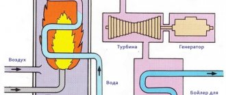
It is believed that the first magneto was built by Pixie in 1832, but the current did not find widespread use. In 1844, Woolrich created a pair of hand generators for galvanizing metals, and these were the first industrial designs. In the mid-50s, energy began to be used by obtaining it from steam and converting it into electricity using a crankshaft and similar gizmos. Page engines were already known to do the exact opposite, pushing trains.
The two-ton, 600-rpm engine, built according to Blackwell's design, is considered the first attempt at creating a fully automatic steam current generator. Paired with it, a mechanical commutator was used to rectify the variable component. In 1858, similar generators began to be used as equipment in English lighthouses. The result did not exceed expectations, but the first step was taken towards supplying energy for the needs of mankind.
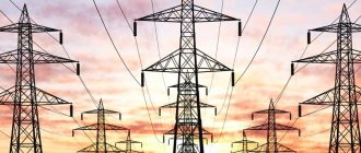
At the same time, demonstrations of electric lighting were taking place in France. There, the novelty served rather to entertain the public. By the early 70s, some lighthouses had firmly switched to electricity, including the Odessa one. The Germans, who had previously remained in the shadow of English and French experiments, appeared on the scene. The organizer and entertainer Oscar von Miller wanted to surpass the foreigners. He ordered the transmission of electrical energy over a distance of 35 miles. What became the first high-voltage network in the world.
The denomination is always indicated
Conditions for normal operation of the electrical network
For stable operation of electrical receivers, the following rule of voltage equality must be observed: the rated voltage of electrical receivers must be equal to the rated voltage of the electrical network. Unom.ep = Unom.network. But in practice it is impossible to ensure such equality in which there will be no losses or damages.
The load of electrical receivers cannot be constant; it changes and deviates from the nominal value. The acceptable voltage deviation zone of the electrical receiver is ±5%.
In addition, the length of the power line implies a loss of voltage on the line, which means that the voltage at the receiver will be less than the voltage at the source. The difference in voltage will be the amount of loss. This is taken into account during the design and according to GOST, the voltages (nom.) generated by generators must be 5% greater than the required network voltage.
Value ranges
The GOST 29322-2014 standard establishes standard voltage values that are intended for use as [2]:
- preferred values for the nominal voltage of electrical power systems;
- reference values for electrical equipment and designed electrical systems.
Table 1 of subsection 3.1 “AC systems and electrical equipment with a rated voltage from 100 V to 1000 V inclusive” of the GOST 29322-2014 standard shows the rated voltages of AC systems in the range from 100 V to 1000 V, which should be used to guide the selection of the rated voltage in electrical distribution networks and electrical installations of buildings connected to them.
| Table 1. AC systems and electrical equipment with rated voltage from 100 V to 1000 V inclusive (based on table 1 from GOST 29322-2014 [2] | ||
| Rated voltage of three-phase four-wire or three-wire systems, V | Rated voltage of single-phase three-wire systems, V | |
| 50 Hz | 60 Hz | 60 Hz |
| – | 120/208 | 120/240d |
| 230c | 240c | – |
| 230/400a | 230/400a | – |
| – | 277/480 | – |
| – | 480 | – |
| – | 347/600 | – |
| – | 600 | – |
| 400/690b | – | – |
| 1000 | – | – |
| a) The 230/400 V value is the result of the evolution of the 220/380 V and 240/415 V systems that have come to the end of use in Europe and many other countries. However, 220/380 V and 240/415 V systems still continue to be used. b) The 400/690 V value is the result of the evolution of the 380/660 V system, which has been completed in Europe and many other countries. However, the 380/660 V system is still used. c) 200 or 220 V is also used in some countries. d) 100/200 V values are also used in some countries for 50 or 60 Hz systems. | ||
The GOST 29322-2014 standard [2] states that Table 1 takes into account the presence of single-phase electrical circuits, which are branches from three-phase four-wire and single-phase three-wire electrical systems. The smaller values in the first and second columns of Table 1 are the voltages between phase and neutral1, the larger values are the voltages between phases2. If a single value is specified, it applies to three-phase, three-wire electrical systems and sets the voltage between phases. The smaller value in the third column of Table 1 is the voltage between phase and neutral, the larger value is the voltage between phase conductors3.
The GOST 29322-2014 standard establishes that under normal operating conditions, the supply voltage4 should not differ from the rated system voltage by more than ±10%. The standard also states that the range of voltages5 used depends on variations in voltage at the supply terminals and voltage drops that may occur in the consumer electrical installation6.
For example, the rated voltage 230/400 V means the following: 230 V is the voltage between phase and neutral, 400 V is the voltage between phases. The voltage at the point of connection of a single-phase electrical installation of a building to a low-voltage electrical network should be equal to 230 V ± 10%, of a three-phase electrical installation of a building - 400 V ± 10%.
Voltages exceeding 230/400 V are intended for use in electrical installations of industrial and large commercial enterprises, since they are characterized by large loads and long electrical circuits.
Explanations for the above:
“ 1) Voltage between phase and neutral - the voltage between the phase and neutral conductors at a given point in the electrical circuit. »
“ 2) Voltage between phases - the voltage between two phase conductors at a given point in the electrical circuit. »
“ 3) In a single-phase three-wire electrical system, network or circuit, there are two phase conductors and a neutral conductor or PEN conductor, and there may also be a protective conductor. »
“4) The term “supply voltage” is defined by GOST 29322-2014 as follows: voltage between phases or voltage between phase and neutral at the power terminals. »
“5) The term “range of voltages used” is defined by the GOST 29322-2014 standard as follows: the range of voltages in plug sockets or at points of fixed electrical installations to which electrical receivers must be connected. »
“ 6) Consumer electrical installations also include electrical installations in buildings. »
The rated voltage of three-phase electrical installations in residential and public buildings, medical institutions and commercial enterprises, as a rule, is 400 V, single-phase - 230 V. This value was established by GOST 29322 back in 1993. However, until now the specified rated voltage has not found proper application in our country. Even at the level of regulatory documents, the values of 220 and 380 V are used.
The highest and lowest voltage values at the power terminals and at the electrical receiver terminals are given in reference Appendix A “The highest and lowest voltage values at the power terminals and electrical receivers for alternating current systems with a rated voltage from 100 V to 1000 V inclusive” of the GOST 29322-2014 standard.
| Table A.1 of the GOST 29322-2014 standard The highest and lowest voltage values at the power terminals and electrical receivers for alternating current systems with a rated voltage from 100 V to 1000 V inclusive | ||||||
| Systems | Rated frequency, Hz | Voltage | ||||
| Highest supply voltage or voltage used2, V | Rated voltage, V | Lowest supply voltage, V | Lowest voltage used, V | |||
| Three-phase four-wire or three-wire systems | 50 | 253 | 230c | 207 | 198 | |
| 253/440 | 230/400c | 207/360 | 198/344 | |||
| 440/759 | 400/690b | 360/621 | 344/593 | |||
| 1100 | 1000 | 900 | 860 | |||
| 60 | 132/229 | 120/208 | 108/187 | 103/179 | ||
| 264 | 240c | 216 | 206 | |||
| 253/440 | 230/400a | 207/360 | 198/344 | |||
| 305/528 | 277/480 | 249/432 | 238/413 | |||
| 528 | 480 | 432 | 413 | |||
| 382/660 | 347/600 | 312/540 | 298/516 | |||
| 660 | 600 | 540 | 516 | |||
| Single-phase three-wire systems | 60 | 132/264 | 120/240d | 108/216 | 103/206 | |
| a), b), c), d) - see text from table 1 2) The term “utilization voltage” is defined by the GOST 29322-2014 standard as follows: voltage between phases or voltage between phase and neutral in plug sockets or at points of fixed electrical installations to which electrical receivers must be connected. | ||||||
Table A.1 shows the highest and lowest voltage values at the power terminals and terminals of electrical receivers. They are calculated according to Table 1 of the GOST 29322-2014 standard and the following instructions given in subsection 525 “Voltage drop in consumer installations” of the IEC 60364-5-52:2001 standard: in the absence of other considerations, it is recommended that in practice the voltage drop between inputs into the user's electrical installation and electrical equipment was no more than 4% of the rated voltage of the electrical installation.
However, in table G.52.1 of the current standard GOST R 50571.5.52-2011 for low-voltage electrical installations connected to public electrical networks, other values for the maximum voltage drop are established:
- for electric lamps – 3%;
- for other electrical receivers – 5%.
Therefore, the values of the lowest voltage used, given in Table A.1 of the IEC 60038 standard, must be consistent with the requirements of the GOST R 50571.5.52-2011 standard. To do this, the last column of Table A.1 should be replaced by two columns containing the values of the lowest voltage used, which are calculated taking into account the maximum voltage drop equal to 3 and 5% of the rated voltage of the electrical installation.
The IEC 60449 standard and its national analogue, GOST 32966-2014 [3], establish two voltage ranges for AC and DC voltages for electrical installations in buildings. Table 1, Section 3, AC Voltage Ranges, provides two AC voltage ranges, and Table 2, Section 4, DC Voltage Ranges, provides two DC voltage ranges. These voltage ranges classify electrical installations depending on their rated voltage.
See these 2 tables combined below:
| Table: rated voltage ranges U of electrical installations. Based on tables 1 and 2 from GOST 32966-2014 | |||
| Ranges | Grounded systems1 | Isolated or ineffectively grounded systems2 | |
| Voltage between phase and ground 3, or between pole and ground 4, V | Voltage between phases or poles, V | Voltage between phases or poles, V | |
| Alternating current | |||
| I | U≤ 50 | U≤ 50 | U≤ 50 |
| II | 50 | 50 | 120 |
| D.C | |||
| I | U ≤ 120 | U ≤ 120 | U ≤ 120 |
| II | 120 | 120 | 120 |
| 1) A grounded system means an electrical system in which one of the live parts is grounded. In this case, in three-phase four-wire and single-phase three-wire AC electrical systems, the neutrals are grounded. In three-phase three-wire and single-phase two-wire AC electrical systems in which there are no neutrals, the phase conductors are grounded. In a three-wire DC electrical system, the middle energized part is grounded. In a two-wire DC electrical system, in which there is no middle part that is energized, the pole conductor is grounded. | |||
| 2) An isolated or ineffectively grounded system means an electrical system in which all live parts are isolated from earth or one of the live parts is grounded through a high impedance. | |||
| 3) Voltage between phase and ground - the voltage between the phase conductor and the reference ground at a given point in the electrical circuit. | |||
| 4) Voltage between pole and ground - the voltage between the pole conductor and the reference ground at a given point in the electrical circuit. | |||
Range II in Table 1 of the GOST 32966-2014 standard [3] covers all rated voltages specified in Table 1 of the GOST 29322-2014 standard. Band I sets the upper limit of extra-low voltage AC that is used in electrical installations of buildings in such protection measures against electric shock as "extra-low voltage provided by SELV and PELV." Table 1 of the GOST 29322-2014 standard indicates rated AC voltages from 100 V to 1000 V, and in low-voltage electrical installations, electrical equipment and electrical circuits operating at voltages less than 100 V are used.
In addition, the GOST 29322-2014 standard does not indicate rated DC voltages for low-voltage electrical installations. Therefore, Table 6 of subsection 3.6 “AC electrical equipment with a rated voltage of less than 120 V and DC electrical equipment with a rated voltage of less than 750 V” of the GOST 29322-2014 standard shows the rated voltages of AC electrical equipment falling in range I, and DC electrical equipment falling in both voltage range (I and II).
| Table 6 of the GOST 29322-2014 standard Electrical equipment of alternating current with a rated voltage of less than 120 V and direct current with a rated voltage of less than 750 V | |||
| D.C | Alternating current | ||
| Rated voltages | Rated voltages | ||
| Preferred, B | Additional, B | Preferred, B | Additional, B |
| — | 2,4 | — | — |
| — | 3 | — | — |
| — | 4 | — | — |
| — | 4,5 | — | — |
| — | 5 | — | 5 |
| 6 | — | 6 | — |
| — | 7,5 | — | — |
| — | 9 | — | — |
| 12 | — | 12 | — |
| — | 15 | — | 15 |
| 24 | — | 24 | — |
| — | 30 | — | — |
| 36 | — | — | 36 |
| — | 40 | — | — |
| 48 | — | 48 | — |
| 60 | — | — | 60 |
| 72 | — | — | — |
| — | 80 | — | — |
| 96 | — | — | — |
| — | — | — | 100 |
| 110 | — | 110 | — |
| — | 125 | — | — |
| 220 | — | — | — |
| — | 250 | — | — |
| 440 | — | — | — |
| — | 600 | — | — |
| Notes: 1) Since cell or battery voltages are less than 2.4 V and the selection of cell or battery type used for different applications is based on criteria other than its voltage, these voltages are not listed in the table. The relevant IEC technical committees may specify cell or battery types and associated voltages for specific applications NOTE 2 For technical and economic reasons, specific applications may require different voltages. | |||
According to Table 6 of the GOST 29322-2014 standard, in AC electrical circuits of electrical installations of buildings operating at ultra-low voltage, electrical equipment that has a rated voltage of 6, 12, 24 and 48 V is usually used. It is also possible to use electrical equipment with a rated voltage of 5, 15 and 36 V. If DC electrical equipment is used in the electrical installation of a building, then, as a rule, it has the rated voltage values indicated in the first two columns of Table 6 of the GOST 29322-2014 standard.
Terms and Definitions
The following terms with corresponding definitions are used in this standard. For AC voltages, the effective values are shown below.
2.1 nominal system voltage : A corresponding approximation of voltage used to designate or identify a system.
2.2 highest voltage of a system (excluding transient or abnormal conditions): The highest value of operating voltage that occurs under normal operating conditions at any time and at any point in the electrical system.
Note: This definition excludes transient overvoltages, for example due to switching operations, and temporary voltage fluctuations.
2.3 Lowest voltage of a system (excluding transient or abnormal conditions): The lowest value of operating voltage that occurs under normal operating conditions at any time and at any point in the electrical system.
Note: This definition excludes transient overvoltages, for example due to switching operations, and temporary voltage fluctuations.
2.4 terminals : A point in a transmission or distribution electrical network, designated as such and specified by contract, at which parties to the contract exchange electrical energy.
2.5 voltage : Voltage between phases or voltage between phase and neutral at the supply terminals.
Note: The equivalent definition is line-to-line voltage or line-to-neutral voltage at the supply terminals.
2.6 voltage range : Voltage range at the supply terminals.
2.7 Utilization voltage : The voltage between phases or the voltage between phase and neutral at socket outlets or at points in fixed electrical installations to which electrical receivers are to be connected.
Note: Equivalent definition: voltage between lines or voltage between line and neutral at socket outlets or at points in fixed electrical installations to which electrical receivers are to be connected.
2.8 Utilization voltage range : The range of voltage at socket outlets or at fixed installation points to which electrical receivers are to be connected.
Note: In some electrical standards (eg IEC 60335-1 and IEC 60071), the term "voltage range" has a different meaning.
2.9 highest voltage for equipment highest voltage for which electrical equipment is rated with respect to: a) insulation; b) other characteristics that may be associated with this highest voltage in the relevant electrical equipment recommendations.
Note: Electrical equipment can only be used on electrical systems having a highest voltage that is less than or equal to its highest voltage for the electrical equipment.
2.10 voltage : The voltage between two phase conductors at a given point in an electrical circuit.
2.11 neutral voltage : The voltage between the phase and neutral conductors at a given point in an electrical circuit.
2.12 Line conductor : A conductor that is energized under normal conditions and used to transmit electrical energy, but is not a neutral conductor or middle conductor.
2.13 Neutral conductor : A conductor electrically connected to a neutral and used to transmit electrical energy.
2.14 phase conductor : Line conductor used in an alternating current electrical circuit.
Varieties
There are two types: constant and variable. The first is in electrostatic types of circuits and those that have direct current. Variable occurs where there is sinusoidal energy. It is important that sinusoidal energy is divided into effective, instantaneous and average rectified. The unit of measurement for electric current voltage is volt.
It is also worth noting that the amount of energy between the phases is called the linear phase, and the indicator of the ground and phase current is called the phase current. A similar rule is used in all overhead lines. On the territory of the Russian Federation, the standard household electrical network is 380 volts, and the phase network is 220 volts.
Main varieties
Constant pressure
Constant is the difference between electrical potentials, at which the same value remains the same with polarity changes over a specific period. The main advantage of constant energy is the fact that there is no reactive power. This means that all the power that is generated by the generator is consumed by the load, excluding wire losses. Flows throughout the entire conductor cross-section.
As for the disadvantages, there is the difficulty of increasing with decreasing energy, that is, at the moment of converting it due to the design of the converters and the lack of powerful semiconductor switches. In addition, it is difficult to decouple high and low energy.
Note! Constant energy is used in electronic circuits, galvanic cells, batteries, electrolysis plants, welding tools, inverter converters and many other devices.
D.C
AC voltage
An alternating current is a current that changes in magnitude and direction periodically, but at the same time maintains its direction in an electrical circuit unchanged. It is often called sinusoidal. One direction in which energy moves is called positive, and the other is called negative. Therefore, the resulting quantity is called positive and negative. This exponent is an algebraic quantity. In answer to the question of what the unit of voltage is called, it should be noted that it is a volt. Its value is determined by direction. The maximum value is amplitude. It happens:
- two-phase;
Two-phase
- three-phase;
Three-phase
- multiphase.
Multiphase
It is actively used in industry, at a power station, at a transformer substation and is transmitted to every home using electrical transmission lines. Mostly three phases are used for connection. This type of electrification is common on many railways.
Note! It is worth noting that there are also some types of dual-system electric locomotives, which operate in many cases at a variable rate.
Alternating current