Definition and features.
Touch voltage is the voltage between conductive parts when they are simultaneously touched by a person or animal (definition according to SP 437.1325800.2018 [1]).
Note on definition: The value of touch voltage can be significantly influenced by the impedance of the human or animal body in electrical contact with these conductive parts.
According to GOST R IEC 61557-1-2005, the following short designation is established for the term in question: Ut
Kharechko Yu.V., having, in my opinion, carried out a thorough analysis of the regulatory documentation, in his book [2] described the features of the concept of “touch voltage” as follows:
“When a person or animal simultaneously touches conductive parts that are under different electrical potentials, it comes under voltage, which in regulatory documentation is called touch voltage. Under these conditions, electrical current will flow through the human (animal) body, which can cause fatal electrocution, cause serious electrical injury, or cause mechanical injury. If a person (animal), having an electrical connection with the ground, touches any conductive part that is energized, then he will also be under touch voltage. An electric current will also flow through the human (animal) body, the magnitude of which depends on the touch voltage and the total resistance of his body. »
[2]
“Human (animal) contact with live conductive parts usually occurs in conditions of single or multiple damage. For example, when, due to damage to the insulation of live parts, they become accessible to touch. However, the most likely result is touching an exposed conductive part of Class 0 or I electrical equipment that has become energized due to damage to the basic insulation of some dangerous live part. It is possible, but less likely, for a person to touch the conductive sheath of Class II electrical equipment that becomes energized when the double or reinforced insulation of a hazardous live part fails. »
[2]
Protective measures.
Yu.V. Kharechko wrote about what protective measures need to be used in order to reduce touch voltage in electrical installations of buildings. in his brief terminological dictionary [2]:
“In order to reduce touch voltage in electrical installations of buildings, protective potential equalization is performed. When it is implemented, open conductive parts of class I electrical equipment are connected to each other using protective conductors, and third-party conductive parts are connected using protective potential equalization conductors. In conditions of increased likelihood of electric shock, when Class I electrical equipment is used, for example, in building areas with conductive floors and walls, characterized by high humidity, temperature and other unfavorable conditions, additional potential equalization is carried out. When it is performed using protective conductors of additional potential equalization, exposed conductive parts of class I electrical equipment are connected to third-party conductive parts. »
[2]
Protective potential equalization is usually used in conjunction with other precautions, such as automatic power off. In this case, by means of a protective potential equalization system, firstly, an artificial conductive path is created for the flow of ground fault current. Secondly, they reduce the touch voltage until the protective device is activated, which turns off the distribution or final electrical circuit with emergency electrical equipment of class I.
Calculation of touch voltage
By performing calculations, the possible value of the current in case of contact is determined. For calculations, two electrical network diagrams are considered:
- circuit with solidly grounded neutral;
- system with isolated neutral.
What voltage should the battery be?
In the first case, when a person is exposed to phase voltage (220 V), the amount of current through it is restrained by the resistance of the circuit: phase - body - shoes - floor (ground). Based on this, the formula looks like:
Ich = Uph/(Rch + Rob + Rp + R0) ≈ Uph / Rch,
Where:
- R0 – resistance of the transformer neutral protective conductor, R0 ≤ 10 Ohm;
- Uph – phase voltage;
- Rch – human resistance;
For linear voltage, the flow current is calculated using the formula:
Ich = Ul/√3*( Rch + Rob + Rp + R0).
In the second case, where the neutral is isolated, they work with the formulas:
- Ich = Ul/Rch – for the moment of two-phase contact;
- Ich = 3Uph/(3Rch + Riz) – a variant of single-phase contacting, where Riz is the insulation resistance of the phase wires in relation to the ground.
Note! If the ground electrode is singular, then touching the body of the device furthest from it will be the most dangerous
Definition of the concept
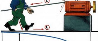
The word “touch” itself expresses the essence of this concept. Voltage is the potential difference between two points. It occurs due to insulation breakdown, induced static electricity or an emergency in the technological process. Touch voltage is electricity that appears on the human body as a result of its contact with points that have different potentials.
If in some place conditions are created for simultaneous touching of two conductive elements, then when a living organism appears there, we can talk about the danger of touch voltage. This electrical quantity can be preliminarily measured in order to have an idea of its expected maximum values.
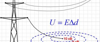
Step Voltage Values
From the physical prerequisites for the occurrence of such an effect, it becomes clear that the magnitude of the step voltage depends on the distance from the ground electrode or fallen wire, and the distance between the feet.
In this case, the following main values can be distinguished:
- Maximum - occurs in cases where one foot is on the wire or on the ground above the grounding electrode, and the second at a distance of 80–100 cm. This is explained by the steepness of the drop in the curve of the potential versus the distance to the grounding point. It is in this area that the potential difference will be maximum.
- The minimum value is possible only at a significant distance from the point of contact of the wire with the ground. In this zone, the dissipation of electric current is no longer observed, so a potential difference does not arise at any step size.
- A zero value is typical for those situations when the feet are on points characterized by identical potentials. This becomes possible if you stand on the elements of a group grounding electrode or keep your feet almost close.
It is on these data that the rules for exiting the step voltage zone that occurs in an emergency are justified. Practice has shown that these recommendations should be followed until the distance to the center of the zone exceeds 20 m.
Also read: How and with which fire extinguishers to extinguish wiring
Types of electrical injuries
Electrical injuries occur due to the action of an arc or current. There are local or general damage to the body.
With local exposure to electricity on the human body, the following may occur:
- burns;
- metallization of the skin;
- electrical signs;
- burn of the cornea of the eyes;
- mechanical injuries to the skin and soft tissues.
They do not pose a danger to life; treatment of local affected areas of the body is required. The exception is burns - if the percentage of damage to the skin surface is too high, death is possible.
The severity of an electric shock depends on the path the electricity takes through the victim's body. There are five degrees of electric shock, which results in the following consequences:
- weak, involuntary muscle contraction - cramps are barely noticeable;
- convulsions with severe pain;
- lack of consciousness without failure of the heart and respiratory organs;
- lack of consciousness with loss of breathing and heartbeat;
- clinical death.
Note! The outcome depends on how quickly the person is freed from the effects of electricity and how successfully medical care is provided.
Paths of current passing through the human body
Question 7. What is meant by touch voltage?
| Voltage between two conductive parts or between a conductive part and ground when simultaneously touched by a person or animal | Correct answer |
| Voltage between two points on the ground due to the spreading of a fault current to the ground when they are simultaneously touched by a person’s feet | |
| The voltage produced when current flows through a conductor between two points | |
| Voltage between two points on the surface of the earth at a distance of 1 m from one another, which is taken to be equal to the length of a person’s step | |
| Voltage between two points in an electrical circuit with different potentials |
Question 8. Which of the following posters are prohibitive?
Do not turn on! People are working. Correct answer Stop! Tension. Don't get involved! Will kill. Be careful! Electrical voltage. Question 9
What type of safety poster is a poster with the inscription “Caution! Electrical voltage?
Question 9
What type of safety poster is a poster with the inscription “Caution! Electrical voltage?
| To those prohibiting | |
| To the warnings | Correct answer |
| Towards prescriptive | |
| To the index fingers |
Question 10. The following should be considered a lethally dangerous amount of electrical alternating current flowing through the human body:
| 20 mA | |
| 40 mA | |
| 60 mA | |
| 100 mA | Correct answer |
Errors made:
Test result:___________________________
No violations of its procedure were recorded during testing.
Responsible for testing
Test taker /______________________________/
EB 141.1 Certification of electrical and electrical engineering personnel for electrical safety (II admission group)
_____________________________________________________________________________
(Full name of the person being tested)
Date of testing: "____"__________ 20_
Allowable number of errors 2
Ticket 15
Question 1. What voltage should be used to power portable (hand-held) lamps used in hazardous areas?
| Not higher than 12 V | |
| Not higher than 42 V | |
| Not higher than 50 V | Correct answer |
| Not higher than 127 V |
Question 2. How are power tools and hand-held electrical machines classified according to the method of protection against electric shock?
| Divided into 4 classes - zero, first, second and third | Correct answer |
| Divided into 3 classes - first, second and third | |
| Divided into 4 classes - first, second, third and fourth | |
| Divided into 3 classes - zero, first and second |
Question 3. Who carries out state supervision of compliance with the requirements of electrical safety rules and regulations in electrical installations?
| Ministry of Emergency Situations | |
| Rostechnadzor | Correct answer |
| Glavgosenergonadzor | |
| Rospotrebnadzor |
Question 4. How many electrical safety approval groups are there?
| Three | |
| Four | |
| Five | Correct answer |
| Six |
Question 5. For what period is a work order issued for work on electrical installations?
| No more than 5 calendar days from the date of commencement of work | |
| No more than 10 calendar days from the date of commencement of work | |
| No more than 15 calendar days from the date of commencement of work | Correct answer |
| No more than 20 calendar days from the date of commencement of work | |
| For the entire duration of the work |
Question 6. Who is allowed to perform electric welding work?
| Workers who have undergone training, instruction and knowledge testing, have the appropriate certificates and an electrical safety group of at least II | Correct answer |
| Workers who have undergone training, instruction and knowledge testing, have the appropriate certificates and an electrical safety group of at least III | |
| Workers who have undergone training, instruction and knowledge testing, have the appropriate certificates and electrical safety group III or IV | |
| Workers who have been trained, instructed and tested for knowledge of work safety |
Question 7. Which objects are classified as ordinary objects in terms of the degree of danger of lightning damage?
studlib.info
Ways to reduce the danger
GOST 12.1.038-82 (2001) dated March 01, 2022 is the main regulatory document that is used to guide when taking the necessary measures. This GOST considers the standards for the maximum possible values of touch voltage.
Induced voltage
To ensure electrical safety for people, the following steps apply:
- installation of protective grounding devices;
- zeroing of working equipment;
- installation of potential equalization systems (EPS);
- fencing and installation of protective shields on live equipment;
- use of reduced voltage in work in areas with increased danger and especially dangerous ones;
- providing personnel with collective and individual protection items: insulated power tools and dielectric means;
- use of residual current devices (RCDs) and alarms.
Grounding devices are designed to protect against phase-to-frame short circuits. They are installed to reduce the voltage between the ground and live parts of electrical installations.
Important! All metal parts of installations, engines, switchboards, consoles, metal housings of power tools and other elements accessible to touch that can conduct current are subject to mandatory grounding.
To protect against extraneous voltage in places where connection to the ground loop is impossible, grounding is used. Using a separate conductor, the device body is connected to a grounded zero. When a phase hits it through this conductor, the short-circuit protection device is triggered.
To reduce the risk of electric shock to people, industrial and domestic premises are equipped with potential equalization systems (PES). They are basic (OSUP) and additional (DOSUP). The main system is independent and provides potential equalization on accessible metal surfaces of the equipment. DOSUP takes additional measures to reduce the level of potential difference in particular cases.
The implementation of protective fences and the installation of shields protect people from accidental contact with live parts. As an additional measure, warning posters are posted on the fences.
In places with increased danger and particularly dangerous work can only be done with power tools whose supply voltage is not higher than 42 V. For this, step-down transformers are used.
Information. Rooms with increased danger include those where there are: a chemically aggressive environment, high humidity (more than 70%), elevated temperature (above 500C), accessible contact with metal parts or concrete floors.
Collective and personal protective equipment (PPE) includes: dielectric mats and stands, boots, galoshes, gloves and tools with insulating handles. The use of such protective kits reduces the risk of touch voltage.
RCD - residual current devices installed in the apartment allow you to control the occurrence of current leaks and dangerous voltage in places with increased danger (kitchen, bathroom). When dangerous quantities appear, the device turns off the power supply until the cause of their occurrence is eliminated.
A way to reduce the risk of electrocution
Basic and additional means of protection against electric current
The insulation of the basic protective equipment can withstand the operating voltage and can touch live parts. The insulation of additional protective equipment is not designed for operating voltage and is used as an additional protective measure to the main protective equipment.
| Means of protection | Up to 1kV | Above 1kV |
| Basic |
|
|
| Additional |
|
|
In addition to those described above, there are fencing and safety protective equipment. Fencing: shields, insulating pads, portable grounding and warning posters.
Safety: helmets, goggles, mittens, gas masks, claws, safety ropes, assembly belts. And to protect against ultra-high voltage electric fields (arcs), portable shielding devices are used - screens.
Dielectric gloves
in installations up to 1 kV they are used as the main protective device, and in installations above 1 kV - as an additional one. You should ensure that there are no tears in the glove, for example by inflating it and seeing if air comes out. They also naturally must be tested like other PPE and have a seal.
Dielectric carpets and galoshes
protect against step voltage and are additional PPE.
Isolation stands
serve not only as the main means of access for short relay operators to the relay compartments of cells in RU-6kV, but also as an additional means of protection against electric shock.
Insulating rods
depending on the voltage class they have different lengths. They consist of three parts: handle, working part and insulated part.
| Rated voltage of the electrical installation, kV | Minimum length of insulating part, m | Minimum handle length, m |
| up to 1kV | not standardized | not standardized |
| 2-15 | 0,7 | 0,3 |
| 15-35 | 1,1 | 0,4 |
| 35-110 | 1,4 | 0,6 |
| 150 | 2,0 | 0,8 |
| 220 | 2,5 | 0,8 |
| 330 | 3,0 | 0,8 |
| 400, 500 | 4,0 | 1,0 |
Portable grounding
installed when working on switched off equipment to protect personnel from the consequences of possible switching on of the equipment.
And here are the actual groundings themselves:
Insulating and electrical clamps
created for different purposes.
Fuses are removed as insulating fuses, for example under load.
Electrical meters measure various quantities, for example, current clamps measure the amount of current. And current measurements are made without breaking the wires directly on the operating equipment.
Well, the posters. They are different: prohibiting, allowing - almost like in traffic regulations.
Latest articles
Most popular
Protection against indirect contact
The main task of protection against indirect contact is to follow the basic rule of protection against electric shock, to turn off the power to the dangerous circuit in time to avoid injury.
According to the standards of PUE ed. 7 (section 1, chapter 1.7.) and IEC 60 364_4_41 (section 413), protection against indirect contact is the following measures:
1.residual current devices 2.3.4.
Important protective measure
6.Grounding schemes
TN (TN-C, TN-S, TN-CS) – power supply from a source with a solidly grounded neutral and with grounding conductors connected to the neutral.
These grounding systems are historically the most used in Russia and the CIS. We will discuss them in more detail in the following articles. Here briefly, the TN system assumes that the power is supplied from a transformer, the common point of the windings of which is grounded. Grounding of parts of the electrical installation itself (house, entrance, apartment, production) is carried out by connecting the grounding wire to the neutral of the transformer. Depending on the actual point of connection to the neutral, the TN-C, TN-S, TN-CS circuits are divided.
TT – power supply from a source with a solidly grounded neutral and with grounding conductors not connected to the neutral;
This system is not typical for our country. However, it finds application in suburban construction of individual housing construction.
IT – grounding system powered from a source with an isolated neutral.
This grounding system, in its autonomy, stands next to the TT system. In all documents they are described in pairs, separately from the TN system.
It is worth noting that TT and IT systems are more widespread in the West, which is why they are given more attention in the IEC than in the PUE
- pue_7
- pue_6
- pue_6_7
Ehto.ru
Prevention
In a timely manner, at least 2 times a year, it is necessary to measure the protective grounding and the phase-zero loop at workplaces.
Eliminate the following causes of electrical injuries:
- failure to comply with safety regulations;
- being near a broken wire;
- contact with exposed parts of electrical installations under power;
- touching parts of equipment that suddenly become energized;
- touching elements of electrical appliances with damaged insulation.
Electrical safety training must be carried out at workplaces.
AC and DC circuits
In DC and AC circuits, U has different properties and produces other effects on conductors. For constant voltage, there are laws for calculating its characteristics, but for alternating voltage, the methods for calculating indicators are noticeably different. Let's look at all the differences and similarities in more detail.
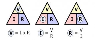
Calculation and analysis of circuits is performed using Ohm's law: the current strength of a complete circuit is directly proportional to the voltage and inversely proportional to the sum of the resistances of the circuit and the power source.
A recording of Ohm's law, from which the formula for voltage, current and resistance follows: I = U / (Rc + Rin), where I is the current strength, U is the emf, Rc is the circuit resistance, Rin is the internal resistance of the power source.
Formula for current through resistance and voltage: I = U / Rc.
Electric current voltage formula: U = I * Rts.
To calculate power, you need to multiply U by I: P = U * I = U * U / R, where P is power.
Single ground
This is the simplest type of equipment grounding, in which there is no need to construct a special circuit. Nevertheless, it is a very effective protective component that allows the protective shutdown to operate and “bypass” a person who has come under voltage.
Single protective earthing includes:
- grounding electrode 2500 mm long - angle steel 50*50*0.5 mm or pipe with a diameter of at least 4 mm;
- grounding conductor - rolled steel wire with a diameter of at least 0.8 mm outdoors and 0.6 indoors or a steel strip 25 mm wide and 0.5 mm thick;
- The connection point for the grounding conductor is a bolt for connection on the electrical installation body.
As a grounding conductor indoors, it is permissible to use a flexible stranded copper wire of yellow-green color, with a cross-section of at least 2.5 mm. All connections are made using electric welding. The seams are at least 10-15 mm long. Welding areas and metal grounding parts (except for the electrode driven into the ground) are painted with black paint to protect against corrosion.
Important! The minimum grounding resistance for a 220 V network should be no more than 8 Ohms, for a three-phase 380 V line the minimum value of R ≤ 4 Ohms. The ground electrode is driven or buried in the ground so that its upper part is 0.4-0.5 m below ground level
The ground electrode is driven or buried into the ground so that its upper part is 0.4-0.5 m below ground level.
Measurement methods
The measurements are carried out by a visiting team of a special laboratory that has a license to perform such measurements. Work and non-work places are measured. Measurements are carried out at an ambient temperature of 5-400C and air humidity of 35-80%.
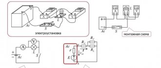
Measuring circuit at the workplace
Attention! The workplace is the area of operation of operational personnel within the framework of the regular work process. A non-work place is an area where there may be people who are not performing official duties related to work in electrical installations.
Before making measurements, the neutral conductor is disconnected from the shield to preliminary measure the resistance of the grounding loop. Next, when assembling the measurement circuit, one output of the device is connected to the protective grounding bus, and the second to the current electrode. Maintaining a distance of more than 25 m from the ground electrode, drive the pin into the ground and install a plate on which a load of 50 kg is placed. This is an imitation of a human leg. The soil under the plate is moistened. The voltmeter V monitors the touch voltage, the resistance R = 1 kOhm is equivalent to the resistance of the human body.
When performing measurements at non-working places, the terminal of the T2 device must be connected to the grounding point of the equipment housing located nearby.
The placement of the current electrode must be done so that the artificial reproduction of the phase voltage ground fault circuit is as accurate as possible.
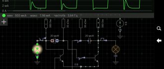
Another measurement method is a circuit using a voltmeter and an ammeter.
The first tests the touch voltage, the second shows the amount of current flowing through the ground electrode. The power source of the measuring circuit is a transformer with an output voltage of 500 V and a rated power of 100 kVA.
Ammeter and Voltmeter Testing