Electrical energy is widely used in production and at home. Alternating current powers lighting systems, drive mechanisms of electrical appliances, and is supplied to the network connector of electronic devices. Sales organizations do not always ensure the proper quality of electrical networks, which manifests itself, in particular, in fluctuations in the network voltage. This unpleasant phenomenon is typical for:
- holiday villages and small settlements;
- networks of autonomous power plants that are not part of a unified energy system.
Fluctuations negatively affect the quality of operation of equipment and reduce its reliability. You can insure yourself against this phenomenon by using a stabilizer, which is connected between the network and the load, Figure 1.
Figure 1. Stabilizer connection diagram
Compensation serial
The compensating series regulator has feedback. In it, the output voltage is compared with a standard. The difference between them is needed to create a signal to the device that controls the voltage.
A certain amount of output voltage is removed from the resistance, which is compared with the main value of the zener diode. This difference is fed to the amplifier and applied to the transistor.
Stable operation is created by a phase shift. Since part of the output voltage is supplied to the amplifier, it shifts the phase by an angle of 180 degrees. A transistor connected like an amplifier does not shift the phases, and the loop shift is 180 degrees.
Pulse
Electric current, which has unstable properties, is supplied through short pulses to a stabilizer storage device, which is a capacitor or coil.
The accumulated energy is then released to the consumer with other properties. There are two ways to stabilize:
- Pulse length control.
- Compare the output voltage with the lowest value.
A switching regulator can vary the voltage with different results. They are divided into types:
- Inverting.
- Up-down.
- Promoting.
- Downward.
Advantages:
Low energy loss.
Flaws:
Interference in the form of pulses at the output.
Series voltage regulator on a bipolar transistor
A series voltage regulator on a bipolar transistor is essentially a parallel parametric stabilizer on a zener diode connected to the input of an emitter follower.
Its output voltage is less than the stabilization voltage of the zener diode due to the voltage drop at the base-emitter junction of the transistor (for silicon transistors - about 0.6 volts, for germanium transistors - about 0.25 volts), which must be taken into account when choosing a zener diode. An emitter follower (also known as a current amplifier) allows you to increase the maximum current of the voltage stabilizer compared to a parallel parametric stabilizer on a zener diode by β (h21e) times (where β (h21e) is the current gain of a given transistor, the smallest value is taken).
Circuit of a series stabilizer based on a bipolar transistor:
Since this stabilizer consists of two parts - a reference voltage source (also known as a parallel parametric stabilizer on a zener diode) and a current amplifier on a transistor (also known as an emitter follower), the calculation of such a stabilizer is carried out similarly to the above example. The only difference: - for example we need to get a load current of 50 mA, then we select a transistor with a gain β (h21e) of at least 10 (β (h21e) = Iload/Ist = 50/5 = 10 - we calculate the power of the ballast resistor using the formula: Рres = Upad * (Ist +Iload)
The load current can be increased several times more if you use a circuit with a composite transistor (two transistors connected according to a Darlington or Sziklai circuit):
That's basically it.
Setup and repair
Nobody repairs microcircuit stabilizers for the reason that it is hardly technically feasible, and the parts themselves cost mere pennies. Such a device does not need to be configured, because it is initially created for one specific voltage.
Power supplies and various voltage converters are quite repairable. Their cost can range from a few to thousands of dollars; for obvious reasons, only expensive models are restored.
LATR is not the cheapest device, but its design is quite simple. Its repair consists mostly of restoring burnt contacts and tightening various fasteners. In rare cases, if the LATR still manages to burn out, then its winding will have to be rewound.
There is a wide selection of adjustable voltage stabilizers. Some are bulky and handle loads of hundreds of watts. Others are no larger than 5 mm in size and easily fit into smartphones. Understanding where, how and what stabilizer to use allows you to use them as efficiently as possible.
Features of connecting the Resanta 10000 stabilizer
Before proceeding with installation, make sure that all operating conditions of this device are taken into account. So, there are restrictions on the temperature at which the device is allowed to operate: from +5 to +40 degrees Celsius. The humidity indicator should not be more than 80%.
It is important that the device has access to air. For this purpose, be sure to leave free space around it (5–10 cm)
If this is a floor-standing model, it should be placed at a distance of 50 cm from the wall. This rule is also relevant for any flammable objects that will stand next to the stabilizer. The sun's rays should not fall on the unit. The stabilizer must be grounded.
Let's look at the connection itself. Resanta 10000 has 5 terminals. Two are designated “L” - phases, the other two “N” - neutral wires. The fifth is allocated for grounding.
First of all, the device is grounded. Next, connect the “input”, with the phase connected to the “L” terminal. The neutral wire is connected to the neutral terminal.
Next, the equipment is turned on and the presence of voltage at the output is checked. After this, the unit turns off. If there is voltage at the output, the output cables are connected according to the same principle as the incoming ones.
If there is no output voltage, then you need to check whether the input wires are connected correctly.
Examples of application of the LM338 stabilizer (connection circuits)
The following examples will show you some very interesting and useful power circuits built using the LM338.
Simple regulated power supply on LM338
This diagram is a typical LM338 harness connection. The power supply circuit provides an adjustable output voltage from 1.25 to the maximum supplied input voltage, which should not exceed 35 volts.
Variable resistor R1 is used to smoothly regulate the output voltage.
Simple 5 Amp Regulated Power Supply
This circuit produces an output voltage that can be equal to the input voltage, but the current varies well and cannot exceed 5 amperes. Resistor R1 is precisely selected to maintain a safe 5 amp limiting current limit that can be drawn from the circuit.
Regulated 15 amp power supply
As mentioned earlier, the LM338 microcircuit alone can handle only 5A maximum, however, if it is necessary to obtain a higher output current, in the region of 15 amperes, then the connection diagram can be modified as follows:
In this case, three LM338 are used to provide high current load with the ability to regulate the output voltage.
Variable resistor R8 is designed for smooth adjustment of the output voltage
Digitally controlled power supply
In the previous power supply circuit, a variable resistor was used to regulate the voltage. The circuit below allows you to obtain the required output voltage levels using a digital signal supplied to the bases of the transistors.
The value of each resistance in the transistor collector circuit is selected in accordance with the required output voltage.
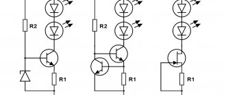
Lighting controller circuit
In addition to power supply, the LM338 IC can also be used as a light controller. The circuit shows a very simple design where a phototransistor replaces a resistor, which is used as a component to regulate the output voltage.
The lamp, the illumination of which must be kept at a stable level, is powered by the output of LM338. Its light falls on the phototransistor. When the illumination increases, the resistance of the photoresistor drops and the output voltage decreases, and this in turn reduces the brightness of the lamp, maintaining it at a stable level.
12V charger for LM338
The following circuit can be used to charge 12 volt lead acid batteries. Resistor R* can be used to set the required charging current for a specific battery.
By selecting resistance R2, you can adjust the required output voltage in accordance with the type of battery.
Smooth switching circuit (soft start) of the power supply
Some sensitive electronic circuits require soft power switching. Adding capacitor C2 to the circuit makes it possible to smoothly increase the output voltage to the set maximum level.
Switching power supply with microcircuit
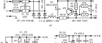
The diagram of a power supply with a microcircuit from the same company Power Integration is shown in Fig. 6. The device uses a semiconductor voltage limiter - 1.5KE250A.
The converter provides galvanic isolation of the output voltage from the mains voltage. With the ratings and elements indicated in the diagram, the device allows you to connect a load that consumes 20 W at a voltage of 24 V. The efficiency of the converter approaches 90%. Conversion frequency - 100 Hz. The device is protected from short circuits in the load.
Rice. 6. Circuit diagram of a 24V switching power supply on a microcircuit from Power Integration.
The output power of the converter is determined by the type of microcircuit used, the main characteristics of which are given in Table 1.
Table 1. Characteristics of TOP221Y - TOP227Y series microcircuits.
| Chip type | Рmax, W | Protection current, A | Open transistor resistance, Ohm |
| TOP221Y | 7 | 0,25 | 31,2 |
| T0P222Y | 15 | 0,5 | 15,6 |
| T0P223Y | 30 | 1 | 7,8 |
| T0P224Y | 45 | 1,5 | 5,2 |
| T0P225Y | 60 | 2 | 3,9 |
| T0P226Y | 75 | 2,5 | 3,1 |
| T0P227Y | 90 | 3 | 2,6 |
Do LED bulbs need to be recycled?
LEDs that have lost their consumer properties are classified as waste of the fourth hazard class, that is, they are considered low-hazard. Materials used during the production stage can have a negative impact on the environment and must be recycled.
Hazard class, waste composition and FKKO code
LED lamps are waste of hazard class IV. Enterprises engaged in the production of lighting equipment are required to carry out their certification. This is described in detail in Russian Government Decree No. 712, issued on September 16, 2013.
Additional information: According to the Federal Classification of Municipal Waste (FKKO), LEDs are designated with the code 4 82 415 01 52 4.
Any LED lamp is multi-component. It consists of:
- base elements;
- aluminum body parts;
- polycarbonate;
- plastic.
All these components must be recycled or used in secondary production after recycling. No chemicals are used in the disposal or recycling process. Sorting is carried out without the use of personal protective equipment.
What the law says, Rospotrebnadzor requirements
LED lighting devices are manufactured in Russia according to GOST R 54815-2011/1EC/PAS 62612/2009. Often people who use such lamps at home throw them into ordinary garbage containers, which is contrary to the requirements of Rospotrebnadzor.
Before recycling LED lamps, the structure must be disassembled into individual elements and sorted by materials. The rest is taken care of by special processing enterprises.
Administrative responsibility for individual entrepreneurs and organizations
If waste LED lighting devices do not have waste certificates for products of the fourth hazard class, the enterprise bears administrative responsibility. According to the current regulatory framework, the violator is obliged to pay penalties in the amount of up to 250 thousand rubles. In addition, organizations can issue an administrative order to suspend activities for up to three months.
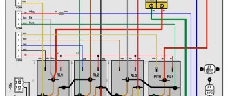
Schemes of 3-phase loads through 1-phase stabilizers
Devices used in everyday life consume less energy than industrial designs. Therefore, for normal network properties, you can use three voltage stabilizers of equal characteristics that correspond to the load for a 1-phase line.
If they use zero separation, then the following scheme is suitable for their installation:
In this diagram, for clarity, the PE protection wire bus is not indicated, and the connection of the stabilizers to it is made in a simplified manner.
The working neutral wire, after the protections located in the switchboard of the house, is divided into the output terminals of each stabilizer. Its bus is created by connecting the output terminals of all three devices in parallel. The zeros to all loads are approached by wire cores from this bus.
The phase terminal, which is included in each stabilizer, is connected to its terminals of the protective device, the output terminal with a group of circuit breakers that supply power to consumers.
If you combine working outgoing and incoming zeros, this makes the circuit simpler. But for some models, this method disrupts some control algorithms in the event of an accident. Therefore, manufacturers carry out this separation.
The diagram shows the connection of similar stabilizers to 3-phase loads.
All diagrams are shown to familiarize yourself with the principle of operation of voltage stabilizers. Therefore, the diagram does not depict switching devices, distribution boxes and other devices.
Connecting the stabilizer to the network
Watch this video on YouTube
Power determination
The stabilizer can be selected based on the total power of all devices, taking into account the reactive component, starting current of electric motors and the number of simultaneously switched on devices. But it is easier to select the power of the stabilizer based on the cutoff current of the circuit breaker installed at the input. It is already designed for the maximum load that the electrical wiring can withstand. Suppose a 50 A circuit breaker is installed, then the power of the stabilizer for a single-phase network is equal to: 50 * 220 = 11000 W (11 kW).
The closest stabilizer power values are 10 and 15 kW. If you do not connect electric heating devices to the stabilizer, which remain operational even at reduced voltage, a lower value is sufficient. At full load, 15 kW is selected to have a reserve, since when the voltage drops, the power of the device itself drops.
The power of a 3-phase stabilizer at a machine current of 16 A is equal to: 16 * 220 * 3 = 10560 W. Close values in this case are 9 and 15 kW. If it is decided to install a stabilizer on each phase, their power is calculated as for a single-phase network.
The simplest do-it-yourself voltage stabilizer
Let's look at how you can make your own 220-volt stabilizer with your own hands, having a few simple parts on hand. If the voltage in your electrical network is significantly reduced, then such a device will come in handy. To make it, you will need a ready-made transformer and a few simple parts. It is better to take note of such an example of a device, since it turns out to be a good device with sufficient power, for example, for a microwave.
For refrigerators and various other household devices, a decrease in network voltage is very harmful, more than an increase. If you increase the network voltage using an autotransformer, then while the network voltage decreases, the voltage at the device output will be normal. And if the voltage in the network becomes normal, then at the output we will get an increased voltage value. For example, let’s take a 24 V transformer. With a line voltage of 190 V, the output of the device will be 210 V; with a network value of 220 V, the output will be 244 V. This is quite acceptable and normal for the operation of household devices.
For manufacturing we need the main part - this is a simple transformer, but not an electronic one. You can find it ready-made, or you can change the data on an existing transformer, for example, from a broken TV. We will connect the transformer according to the autotransformer circuit. The output voltage will be approximately 11% higher than the mains voltage.
In this case, you need to be careful, since during a significant voltage drop in the network upward, the output of the device will produce a voltage that significantly exceeds the permissible value. The autotransformer will add only 11% to the line voltage
This means that the power of the autotransformer is also taken at 11% of the consumer’s power. For example, the power of a microwave oven is 700 W, which means we take a transformer of 80 W. But it’s better to take power with a reserve
The autotransformer will add only 11% to the line voltage. This means that the power of the autotransformer is also taken at 11% of the consumer’s power. For example, the power of a microwave oven is 700 W, which means we take a transformer of 80 W. But it is better to take power with a reserve.
The SA1 regulator makes it possible, if necessary, to connect the consumer load without an autotransformer. Of course, this is not a full-fledged stabilizer, but its production does not require large investments and a lot of time.
Homemade voltage stabilizer
Watch this video on YouTube
Other types
In addition to the main types, stabilizers with other operating principles are sometimes used. Ferroresonant ones are quite acceptable for small houses. The principle of operation is based on the phenomenon of ferroresonance between windings wound on the same core and connected through capacitors. They have high speed and reliability. Disadvantages include low efficiency, increased noise level, significant weight and size, and high cost.
Evgeniy Filimonov
Ask a Question
Electronic stabilizers with a double inverter conversion system 100% compensate for any voltage surges.
However, their cost is very high, so it is better to use such devices as additional protection for one valuable device if frequent voltage fluctuations occur in the power supply (for example, a neighbor does welding work every day). But if your income allows, you can purchase a powerful device to protect your entire home.
Characteristics
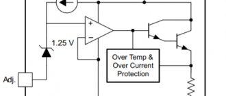
A typical integrated stabilizer circuit consists of the following elements:
- reference voltage source;
- error amplifier;
- adjustment elements connected between the source and the load;
- circuit for turning off the device when a signal is supplied from the outside;
- transistor for protection against short circuit or overload.
Integrated stabilizer chips are functionally complete devices and have only three external pins: input, output and ground. These microcircuits are manufactured for fixed voltage values from 5 to 24 V and loads up to 1 A.
Stabilization devices on the IC are provided with built-in circuits that limit the output current, as well as an overload protection circuit for temperature.
Basic configuration
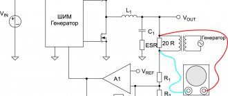
The main task of the stabilizer is to ensure constant output voltage and suppress ripple. The design of the stabilizer is based on the simplest circuit, but I chose each of its elements so that it ideally fulfills its function:
To maximize input noise suppression, the resistance of the resistor R should be as high as possible, and the internal resistance of the reference voltage source Vref should be as low as possible. And the reference voltage driver will work better if it is powered from a high-resistance source. A stable current source (GST) meets these requirements.
For the high-voltage stabilizer, I used a GST with two transistors, which provides greater current stability when the supply voltage fluctuates.
For low-voltage stabilizers, you can use a similar circuit or just a single diode.
For high-voltage stabilizers, I chose a GST current value of about 5mA. For low-voltage stabilizers, you can choose a lower value.
The TL431 chip requires a minimum of 2 mA for normal operation.
Important note: The two-transistor GST can sometimes be excited if high-frequency transistors are used. Therefore, I chose MJ340/350 transistors which, as my experience shows, work stably
Zener diodes are quite noisy and also have a poor temperature coefficient. The output voltage when using them will vary depending on the ambient temperature, and even more so if your amplifier has active ventilation. In addition, the stability of their internal resistance also leaves much to be desired.
I used a TL431 as a voltage reference instead, as their noise performance is quite decent, they have low output impedance and a fairly wide output voltage range that can be set using a simple divider.
Series regulator
This is a stabilizer installed in series with respect to the load. The series regulator consists of a zener diode (VR1), a current limiting resistance (R1), and a load resistance (RL).
The zener diode and the current limiting resistor are connected in series to form a voltage divider. The base of the transistor is connected to the voltage divider. The emitter-collector transistor circuit is connected in series with the load resistance.
Diagram of a series stabilizer connected to a bridge rectifier
Since the transistor is in a series regulator, the voltage acting on the base of the transistor is equal to the voltage drop in the zener diode. This potential is positive relative to the emitter of the transistor. Since the zener diode maintains the voltage drop at a constant level, the potential acting on the base of the transistor will remain constant.
A series regulator maintains a constant level of voltage applied to the load by varying the amount of voltage drop across the transistor. An increase in current through the load can be caused either by an increase in the power supply voltage or by a decrease in load resistance. As the current increases, the voltage drop across the load also increases. As a result, the voltage applied to the emitter of the transistor increases, making it more positive. This means that the electrical potential difference between the emitter and base becomes smaller, so the internal resistance of the transistor increases.
The principle of operation of a zener diode
When the diode is turned on in the forward direction (anode – “+”, cathode – “-”), it freely begins to pass current at voltage Uthr
current Irev
, which has a value of several μA,
can pass through the diode If you increase the reverse voltage Urev
on the diode to a certain
value Urev.max,
an electrical breakdown of the diode will occur, and if the current is sufficiently high, then thermal breakdown occurs and the diode fails. A diode can be made to operate in the electrical breakdown region by limiting the current that passes through the diode (breakdown voltage for different diodes is 50 - 200 V).
The zener diode is designed in such a way that its current-voltage characteristic in the breakdown region is highly linear, and the breakdown voltage is quite constant. Thus, we can say that voltage stabilization by a zener diode is carried out when it operates on the reverse branch
volt-ampere characteristic, in the region of
the direct branch
the zener diode behaves similarly to an ordinary diode.
Zener diode is designated as follows Zener diode designation
Connecting a voltage stabilizer
One of the reasons why household appliances and electrical appliances fail prematurely is sudden voltage drops in the electrical network.
To prevent these undesirable situations, stabilizers are used - protective devices that protect household and industrial equipment from interference and voltage distortion.
Protection is provided by an electronic circuit that monitors the value of the input voltage, which turns off the load when it goes beyond acceptable limits. The load is connected when the network parameter values return to acceptable limits.
Diagram for connecting a voltage stabilizer to a 220 V network
The voltage stabilizer is connected when the network is de-energized. This is a basic safety requirement. To perform this, the input circuit breaker located in the distribution cabinet is turned off, after which it is necessary to finally verify that there is no voltage using a pointer.
In most cases, the stabilizer is turned on immediately after the meter, at the entrance to the room, before the load. Connection type – serial, in phase wire break. Quite often, manufacturers of electronic products designate the structural diagram of the stabilizer on the surface of the case.
The voltage stabilizer usually has three contacts for connection:
- – phase – “input”;
- – phase – “output”;
- – zero.
The phase wire from the input circuit breaker is connected to the “input” of the stabilizer. Then the load phase wire is connected to the “output”. The neutral wire of the network is connected to the neutral contact of the stabilizer without breaking.
To connect the neutral wire, you must first connect it to the stabilizer, and then to the common neutral wire of the network (using terminal connectors (blocks) or regular twisting).
What to do if there are four connection contacts on the stabilizer body?
In some cases, the voltage stabilizer circuit is designed in such a way that not three, but four contacts are used to connect it to the network:
- – phase – “input”;
- – zero – “input”;
- – phase – “output”;
- – zero – “exit”.
In this case, the voltage stabilizer circuit, according to which it is connected to the network, is performed as follows: the phase and neutral wires from the input circuit breaker (electrical panel) are connected to the corresponding “input” contacts on the protective device, and the phase and neutral load wires are connected to the “output” contacts "
After installation, you should carefully check that the wires are connected correctly. Before turning on the device for the first time (applying voltage to the input), it is necessary to disconnect all the load from its output (lighting, remove the plugs of electrical appliances from sockets, etc.).
After turning on the stabilizer, you need to check its operation; it should work stably and normally without extraneous noise, crackling, etc.
Some low-power voltage stabilizers (P
General concepts
The principle of arc welding is well known. Let's refresh our memory of the basic concepts. To obtain a welding joint, an arc must be created. An electric arc occurs when voltage is applied between the welding electrode and the surface of the material being welded. The arc current melts the metal, forming a molten pool between the two ends. After the seam has cooled, we obtain a strong connection between the two metals.
In Russia, alternating current is regulated at a frequency of 50 Hz. Power for the welding machine is supplied from the mains with a phase voltage of 220 V. Welding transformers have two windings: primary and secondary. The secondary voltage of the transformer is 70 V.
Separate manual and automatic welding modes. In a home workshop, welding is carried out manually. We list the parameters that can be changed manually:
- welding current;
- arc voltage;
- welding electrode speed;
- number of passes per seam;
- diameter and brand of electrode.
The correct selection and maintenance of the necessary parameters throughout the welding process are the key to a high-quality welded joint.
When carrying out manual arc welding, it is necessary to correctly distribute the current. This will allow you to make a high-quality seam. The stability of the arc directly depends on the magnitude of the welding current. Experts select it based on the diameter of the electrodes and the thickness of the materials being welded.
Connecting the stabilizer to 380 V
If we consider the design of the unit, the three-phase stabilizer is made in the form of three single-phase devices, where each is responsible for stabilizing the single-phase voltage. Before starting installation work, you must carefully read the attached instructions and strictly follow all of its points.
Based on the connection method, three-phase stabilizers come in two types. The first type of equipment is characterized by three modules with three terminals, to which the wires are connected. The input and output of the “phase” and the neutral cable (input, three modules and the power circuit) are connected to the terminals. Each individual module is connected to a single-phase network.
The second type of unit also has three single-phase stabilizers, each with 4 terminals for connecting wires. In addition to the “phase” input and output, the “zero” input and output are also connected to them. This allows the neutral wire of the power input to operate separately from the neutral wire of the stabilized electrical network.
Three single-phase units or one three-phase unit can be connected to a three-phase network. Each option has its own advantages.
The first one has this:
- For each phase it becomes possible to select equipment of individual capacity;
- Based on operating conditions, a specific type of unit is selected for each phase;
- Three single-phase devices will be slightly cheaper compared to one three-phase one;
- Single-phase models are easier to transport;
- If service is required, only the device of the three that requires intervention is turned off.
The advantage of connecting a three-phase unit to a similar network:
A three-phase consumer is connected without any problems. However, there are certain disadvantages that should be taken into account: Stabilizers of this type are only electromechanical, and this can become a problem with frequent power surges; Difficulties in transportation. This is determined not only by their weight and dimensions, but also by the fact that they can only be transported in an upright position; It is impossible to distribute power across phases depending on the consumer.
Types of stabilizers
Two types of integrated stabilizers are widely used in electronics:
- semiconductor (solid-state);
- hybrid-film (with elements made from films).
Semiconductor stabilizers, in turn, are divided into several groups:
- having adjustable output voltage - require the connection of additional elements;
- having a fixed voltage supplied to the output - they are a ready-to-use product that does not require additional connections to the circuit;
- bipolar – used for devices requiring bipolar output voltage.
Tags: machine, ampere, sconce, type, harm, choice, house, grounding, sign, cable, like, capacitor, design, installation, power, load, voltage, neutral, lighting, variable, connection, constant, potential , rule, principle, wire, start, , work, size, calculation, resistor, row, light, lamp, LED, network, connection, resistance, means, term, stabilizer, zener diode, circuit, ten, type, current, transistor, transformer, three-phase, , phase, photo, photoresistor, shield, electronic, electrical panel
Electronic devices
These stabilizers use thyristors or triacs instead of relays, which makes it possible to maintain normal output voltage when the input drops to 60 V. The absence of moving elements ensures quiet operation and a long service life, which is why they are used even in city apartments. Due to the use of a large number of control elements, the control step is smaller than that of relay analogues. The main disadvantage is the high cost.
The advantages include:
- large, starting from 60 V, operating range;
- absolute silence;
- smooth adjustment;
- high accuracy of maintaining output parameters;
- convenient wall mounting;
- extended warranty up to 3 years.