Periodic alternating current
One that, while changing, manages to return to its original value at equal time intervals and at the same time goes through the entire cycle of its transformations, is called periodic. It can be traced on a sinusoid displayed on the oscilloscope screen.
Period and amplitude of sinusoidal oscillation
It can be seen that at regular intervals the graph repeats without changes. These intervals are designated by the letter T and are called periods. The frequency with which a certain number of similar periods fits into a unit of time is the frequency of an alternating current.
It can be calculated using the AC frequency formula:
f = 1/T,
Where:
- f – frequency, Hz;
- T – period, s.
Frequency is equal to the number of cycles per second and has a unit of 1 hertz (Hz).
Attention! The SI unit of frequency is named after Heinrich Hertz. 1 hertz (Hz, Hz) = 1 s-1
Multiple and submultiple units, expressed by standard SI prefixes, are applicable to it.
Frequency standards
In order to ensure coordination of the operation of sources of alternating electricity, transmission systems, reception and operation of electrical consumers, frequency standards are applied. Frequency used in electrical engineering in some countries:
- 50 Hz – countries of the former USSR, the Baltic states, European countries, Australia, North Korea and others;
- 60 Hz is the standard adopted in the USA, Canada, the Dominican Republic, Taiwan, the Cayman Islands, Cuba, Costa Rica, South Korea and some other countries.
In Japan, both frequencies are used. Eastern regions (Tokyo, Sendai, Kawasaki) use 50 Hz. Western regions (Kyoto, Hiroshima, Nagoya, Okinawa) use a frequency of 60 Hz.
For your information. The railway infrastructure of Austria, Norway, Germany, Switzerland and Sweden still uses the 16.6 Hz frequency.
Units
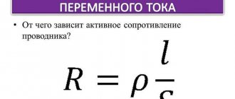
In the International System of Units (SI), the unit of electrical resistance is called the “ohm” in honor of the physicist Georg Ohm. By definition, an electrical resistance of 1 ohm has a section of the circuit where the voltage drops 1 V at a current of 1 A.
The unit of measurement of resistivity is derived from the units of quantities included in the formula: resistance, length and area. That is, in the SI system it turns out that if R = 1 Ohm, S = 1 m 2, and L = 1 m, then ρ = 1.
This is the unit of measurement for resistivity. But in practice it turned out that real wires have a cross-sectional area much less than 1 m2. Therefore, when calculating ρ, it was decided to use the value of the area S in mm 2 so that the final value has a compact form. Then we get more convenient (fewer zeros after the decimal point) numerical values of resistivity for perception:
Electrification of railways using alternating current[edit]
The Russian AC passenger electric locomotive EP1P is produced at the Novocherkassk Electric Locomotive Plant.
In Russia and the republics of the former USSR, about half of all railways are electrified using single-phase alternating current with a frequency of 50 Hz. Voltage ~ 25 kV (usually up to 27.5 kV, taking into account losses)
is fed to the contact wire, the second (return) wire is the rails.
Electrification is also carried out according to the 2 × 25 kV (two twenty-five kilovolts each)
, when a voltage of ~ 50 kV is applied to a separate supply wire
(usually up to 55 kV, taking into account losses)
, and half the voltage of 50 kV is applied to the contact wire from autotransformers
(i.e. 25 kV)
. Electric locomotives and AC electric trains do not require alteration when operating on 2 × 25 kV sections.
A policy is being pursued to further expand the AC traction range both through newly electrified sections and through the transfer of some lines from direct current to alternating current. Transferred to 1990s - 2000s:
- on the East Siberian Railway: section Slyudyanka - Irkutsk - Zima; - on the Oktyabrskaya Railway: section Loukhi - Murmansk; — on the Volga Railway: Saratov and Volgograd railway junctions; - on the North Caucasus Railway: sections Mineralnye Vody - Kislovodsk and Beshtau - Zheleznovodsk.
It should be noted that dual-system electric locomotives are also produced that can operate on both alternating and direct current (see VL61D, VL82 and VL82M, EP10, EP20).
Is it possible to represent the effective (effective) values of e. by vectors? d.s. and currents?
This important question usually causes confusion. You can answer it as follows.
If you need to determine the instantaneous values of a sinusoidal quantity, then it is more convenient to take the vector representing its maximum value, because it is its projection onto the axis that gives the instantaneous values. But in practical activities, they usually deal not with instantaneous values, but with 2 effective values, for example, they say 220 V, meaning by this the effective value and without thinking about the maximum values, which are 41% greater, or about other instantaneous values. Therefore, vector diagrams are usually constructed for effective values. In this case, the phase shift angles between the current, e. d.s., voltage and the like are visible quite clearly, and the results of addition and subtraction of vectors are directly obtained in effective values, which is convenient.
Instantaneous power in an alternating current circuit with active resistance.
With variable voltage and current values, the rate of conversion of electrical energy in the receiver, i.e. its power, also changes. Instantaneous power is equal to the product of instantaneous voltage and current values: p = Umsinωt * Imsinωt = UmImsin2ωt
From trigonometry we find
A more clear idea of the nature of the change in power in a circuit is given by a graph in a rectangular coordinate system, which is constructed after multiplying the ordinates of the voltage and current curves corresponding to a number of values of their common argument - time t. The dependence of power on time is a periodic curve (Fig. 13.2). If the time axis t is raised according to the drawing by the amount p = Pm√2 = UmIm√2, then relative to the new axis t' the power graph is a sinusoid with double frequency and an initial phase of 90°:
Thus, in the original coordinate system, the instantaneous power is equal to the sum of the constant value Р = UmIm√2 and the variable р':
p = P + p'
Analyzing the instantaneous power graph, it is easy to notice that the power remains positive during the period, although the current and voltage change their sign. This is achieved due to the phase coincidence of voltage and current.
The constancy of the power sign indicates that the direction of the flow of electrical energy remains unchanged during the period, in this case from the network (from the energy source) to the receiver with resistance R, where the electrical energy is irreversibly converted into another type of energy. In this case, electrical energy is called active.
If R is the resistance of the conductor, then, in accordance with the Lenz-Joule law, electrical energy in it is converted into heat.
Voltage or potential difference?
It should be noted that voltage and potential difference are one and the same thing. Essentially, it is a force that can cause electrical charges to move in a stream. It doesn't matter where this movement is directed.
Potential difference is simply another expression for voltage. It is clearer and perhaps clearer, but it does not change the essence of the matter. Therefore, the main question is where the voltage comes from and what it depends on.
As far as the 220 Volt home network is concerned, the answer is simple. At a hydroelectric power station, the flow of water rotates the generator rotor. The rotational energy is transformed into tension. A nuclear power plant first turns water into steam. He turns the turbine. In a gasoline power plant, the rotor is rotated by the force of burning gasoline. There are other sources, but the essence is always the same: energy turns into tension.
It's time to ask the question about the dependence of voltage on frequency. But we don't yet know where the frequency comes from.
High frequency currents
HDTV – this is their abbreviation; they are used for melting metals and hardening the surface of metal products. HDTV are currents with a frequency of more than 10 kHz. Induction furnaces use HDTV by placing a conductor inside a winding through which the HDTV is passed. Under their influence, eddy currents arising in the conductor heat it up. By adjusting the strength of the HDTV, the temperature and heating rate are controlled.
Interesting. The metal to be melted can be suspended in a vacuum using a magnetic field. It does not require a crucible (a special ladle for heating). This is how very pure substances are obtained.
Advantages of using HDTV in different cases:
- rapid heating during forging and rolling of metal;
- optimal temperature conditions for soldering or welding parts;
- melt even very refractory alloys;
- cooking in microwave ovens;
- Darsonvalization in medicine.
HDTV is obtained using installations that include an oscillating circuit or electric machine generators. The stator and rotor of the generators have teeth on the sides facing each other. Their mutual movement generates a pulsation of the magnetic field. The greater the product of the number of rotor teeth and its rotation frequency, the greater the output frequency.
Effective value of alternating sinusoidal current[edit]
If all the positive and negative instantaneous values of the alternating sinusoidal current are added, then their sum will be equal to zero.
But if the algebraic sum of all instantaneous values for a period is equal to zero, then the average value of this current for a period is also equal to zero: . The average value of the sinusoidal current over a period cannot be used to measure this current.
To judge the magnitude of the alternating sinusoidal current, alternating current is compared with direct current by their thermal effect.
Two currents, one of which is sinusoidal and the other constant, are equivalent in thermal effect if they, flowing through the same resistances, emit the same amount of heat over the same periods of time. The effective value of an alternating sinusoidal current is numerically equal to a direct current, equivalent to a given sinusoidal current, that is, separately releasing the same amount of heat in the same resistance over the same period of time.
It was found experimentally, and then confirmed theoretically, that the magnitude of the effective value of the alternating sinusoidal current is in a strictly defined dependence on the amplitude of this current: that is, the effective value of the alternating sinusoidal current is several times less than the amplitude of this current.
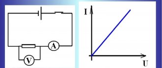
The ammeter of an electromagnetic or electrodynamic system, connected to an alternating sinusoidal current circuit, shows the effective value of the current.
Similar to the effective value of an alternating sinusoidal current, we can talk about the effective value of an alternating sinusoidal electromotive force or an alternating sinusoidal voltage.
The effective value of the voltage is less than its amplitude:
or.
A voltmeter of an electromagnetic or electrodynamic system connected to an alternating sinusoidal current network shows the effective value of the sinusoidal voltage.
For example, in an electrical outlet the electrical voltage
is RMS value , the peak voltage will be Volts.
These formulas are valid only for sinusoidal current; if the pulses are triangular, sawtooth, rectangular or other in shape, a different calculation method is required.
Using the method of mathematical analysis, it is possible to determine the average value of an alternating sinusoidal current over half a period, for example, over a positive half-wave of a sinusoid.
The average value of alternating sinusoidal current for half a period is
.
You can also determine the ratio of the effective current value to the average value for half a period (positive half-wave). This ratio for a sinusoidal current is:
.
What currents are there?
Energy is required to power electrical devices and electrical equipment. Direct and alternating currents are a way of transferring energy from one point to another using conductors.
Important! The main difference between them is the nature of the movement of charged particles. Direct current flows uniformly in one direction, while alternating current constantly changes direction at a given speed or frequency. The main consequence of this is voltage polarity.
Constant
Direct current is characterized by a constant indicator of the polarity of charged particles. Since direct current maintains a constant polarity, it is important to pay attention to how the device is connected - incorrectly connecting the device to the network will most likely damage it. A good example is battery-powered devices - they are always marked with markings to ensure they are connected correctly. Otherwise, the equipment simply will not work, as it will not receive power.
Important! When using direct current, the voltage reading can vary greatly depending on the device used. Typical rated voltages of autonomous power supplies are 1.5V, 3.7V, 6V, 9V,12V, 24V, etc.
Changing the direction of current
Variable
With alternating current, the polarity constantly switches between positive and negative values. With such a characteristic of the force field, the voltage will constantly change, and the polarity in this case does not have any effect on the performance of the network. That is why any household electrical device can be plugged into the network without thinking about the position of the plug in the outlet, that is, about maintaining the correct polarity.
The main reason for the widespread use of alternating current is the relative ease and efficiency of increasing or decreasing voltage. This is achieved using transformers, and the number of changes in quantitative indicators is determined by the number of windings.
Important! The same transformation is allowed for a constant value, but this phenomenon is not effective for its application in practice. Also, this is another, additional reason why alternating current is used in the household network.
Phases in the battery
Although lower voltages are easier to generate, higher voltages incur less losses when transmitted over distances. Therefore, before supplying consumers, the alternating voltage is increased to several hundred kilovolts. But, once the electricity reaches its destination, it drops to 110 or 220 volts. The fact is that the variable indicator has two established standard voltages that are used all over the world: 220V and 110V. Frequency plays a decisive role in electrical engineering, and devices designed for a voltage of 110V will not operate on a 220V network.
Generating alternating current[edit]
The simplest alternating current generator: if a flywheel with several pairs of permanent magnets installed in it is rotated around a wire coil wound on a magnetic core made of transformer steel, then a sinusoidal EMF will be induced in the coil (conventionally shown as one turn), and when a load is connected, an alternating current will appear in the electrical circuit current. Used on vehicles (mopeds, light motorcycles, snowmobiles, jet skis, as well as outboard boat motors), works in conjunction with a rectifier and voltage regulator (see Magdino)
.
Main article: Alternator
The operating principle of an alternating current generator is based on the law of electromagnetic induction - the induction of an electromotive force in a rectangular loop (wire frame) located in a uniform rotating magnetic field.
The electromotive force of an alternator is determined by the formula:
, Where
— number of turns;
- magnetic induction of the magnetic field in volt-seconds per square meter ( T
,
Tesla
);
— the length of each of the active sides of the circuit in meters;
— angular velocity of the sinusoidal electromotive force, in this case equal to the angular velocity of rotation of the magnet in the circuit;
— phase of the sinusoidal electromotive force.
The frequency of the alternating current generated by the generator is determined by the formula:
, Where
— frequency in hertz;
— number of rotor revolutions per minute;
— number of pairs of poles.
According to the number of phases, alternating current generators are:
- three-phase generators are the main type of powerful industrial generators; See also three-phase power supply system, three-phase motor, three-phase alternating current automobile generator
. - single-phase generators, used, as a rule, in low-power gasoline power plants, built into internal combustion engines of mopeds, light motorcycles, snowmobiles, jet skis, and outboard boat engines; See also capacitor motor, single-phase motor
. - two-phase generators are much less common compared to single-phase and three-phase. See also two-phase electrical network, two-phase motor
.
Modified sine wave generated by an inverter.
Invertersedit
Direct current can be converted to alternating current using an inverter.
It should be noted that inexpensive inverter models have a non-sinusoidal alternating current output, usually rectangular pulses or a modified sine wave. To produce a sinusoidal current, the inverter must have a master oscillator (usually a specialized microcircuit that generates a sinusoidal electrical signal, which then controls the operation of thyristor or transistor electronic switches.
Phase splitteredit
Three-phase current can be obtained from single-phase current using a phase splitter. These electric machines are used, in particular, on electric locomotives such as VL60, VL80.
What are the phases in the current?
Only alternating current can be multiphase. There are 3 different phases in total, and they are all shifted 120 degrees relative to each other. Each power station produces 4 wires: 3 phase and one for grounding, which is common to all three. The power plant produces three different phases of alternating current simultaneously, and these three phases are shifted strictly at a certain angle.
Phase arrangement
Why three phases? Why not one, two or four? In 1-phase and 2-phase power supplies, a phenomenon occurs when the sine wave crosses the zero mark 120 times per second. With three-phase power, at any given moment one of the three phases is approaching peak. Thus, high-power 3-phase motors (used in industry) and other devices such as 3-phase welding equipment have a uniform power output.
Important! Four phases will not significantly improve the situation, but it will add a fourth wire, which will increase the complexity of many works and maintenance, so 3 phases is the generally accepted and optimal value.
Three-phase
Three-phase power is a common method of generating, transmitting and distributing variable power. It is a type of multiphase system and the most common method used by electrical networks around the world to transmit energy. It is also used to power large motors and when heavy loads are encountered.
A three-phase circuit is generally more economical than an equivalent two-wire single-phase circuit at the same line voltage and grounding because less conductor material is used to transmit a given amount of electrical energy.
Interesting fact: Polyphase power systems were invented by Galileo Ferrari, Mikhail Dolivo-Dobrovolsky, Jonas Wenström, John Hopkinson and Nikola Tesla back in the late 1880s, and the basic operating principles are still used today.
Particle movement
Two-phase
Two-phase electrical power was the only AC power distribution system available in the early 20th century. At that time, two circuits were used, and the voltage phases differed by a quarter of a cycle, that is, by 90°. Typically, circuits used four wires, two for each phase. Less commonly used were three wires with a common core, but of a larger diameter. Some two-phase generators of yesteryear had two complete rotor assemblies with physically offset windings to provide two-phase power.
Today, two-phase power supply has become widespread in everyday life, since every consumer - resident of an apartment or private house - has a certain number of connection points for low-power household appliances.
Important! With the standard operation of the most common household appliances, a two-phase electrical circuit fully satisfies the needs of residential property owners.
The turbine generator plants at Niagara Falls, built in 1895, were the largest in the world at that time and were precisely two-phase machines. However, ultimately, three-phase systems replaced the hopelessly outdated and inefficient original units for generating and transmitting energy. There are currently few industrial two-phase distribution systems left in the world, such as those in Philadelphia, Pennsylvania.
Two-phase current
How to calculate Xc
The current strength of a circuit with constant voltage readings at the time of operation of the electric capacitor is equal to 0. Its value in a circuit with alternating voltage after connecting the capacitor I? 0. As a result, the capacitor imparts less Xc to a chain with a variable voltage than to a chain with a constant voltage.
Formula for calculating voltage in one second
Formula for calculating the amount of electric current in an instant
It turns out that voltage changes differ in phase from current changes by π/2.
According to the law formulated by Ohm, the strength of the electric current is directly proportional to the magnitude of the circuit voltage. Formula for calculating the largest values of voltage and current:
The largest values of voltage and current can be calculated using the formula: The final formula for calculating capacitance in an alternating current circuit
ω = 2πf.
f is an indicator of the frequency of intermittent current, measured in hertz;
ω is an indicator of the angular frequency of the current;
C is the size of the capacitor in farads.
Important! Xc is not a parameter of the conductor; it depends on such characteristics of the electrical circuit as the frequency of the electric current. Increasing the values of this value causes an increase in the transmittance of the capacitor (the limit of its resistance to intermittent current decreases)
Increasing the values of this value causes an increase in the transmitting capacity of the capacitor (the limit of its resistance to intermittent current decreases).
Let's imagine that a capacitor with a capacity of 1 μF is connected to the circuit. It is necessary to calculate the level of capacitance at a frequency of 50 Hz and how the capacitance of the AC circuit changes at a frequency of 1 kHz. The voltage amplitude applied to the capacitor is 50 V.
After entering the data into the formula that determines Xc, the following values are obtained:
Result for frequency 50 Hz Result for 1 kHz
Capacitive reactance is equated to the ratio of deviations in voltage fluctuations of the terminals of an electrical chain with capacitive parameters (with small inductive and active resistances) to fluctuations in the electric current of the chain. It is equivalent to an electric capacitor.
Electromagnetic vibrations
Electromagnetic oscillations are a repeating process of mutual conversion of electric and magnetic fields.
Electromagnetic oscillations arise in an oscillatory circuit.
An oscillatory circuit is a circuit consisting of a capacitor and an inductor (Fig. 316).
If the resistance of the circuit wires can be neglected, then such a circuit is called ideal.
When charging a capacitor in an ideal oscillatory circuit, free, undamped electromagnetic oscillations of charge and voltage occur on the capacitor plates, as well as current and emf in the inductor. Electromagnetic oscillations in an ideal oscillatory circuit are high-frequency and harmonic.
In Fig. 317 shows graphs of charge, voltage and current fluctuations in an ideal oscillatory circuit.
Below are the equations for electromagnetic oscillations and waves.
Equations of electromagnetic oscillations of charge, current, voltage and emf:
Here q is the instantaneous charge (C), is the maximum charge (C), is the cyclic frequency of oscillations (rad/s), t is the oscillation time (s), is the initial phase (rad), i is the instantaneous current (A), - maximum current (A), u - instantaneous voltage (V), - maximum voltage (V), e - instantaneous emf (V), - maximum emf (V), S - area of the rotating circuit, C - capacitor capacitance (F ).
Period, cyclic frequency and frequency of free electromagnetic oscillations in an oscillatory circuit (Thomson formula)
Here T is the oscillation period (s), L is the inductance of the coil (H), C is the capacitance of the capacitor (F), is the cyclic frequency of oscillations (rad/s), v is the oscillation frequency (Hz).
AC power formula:
Here i is the instantaneous current (A), is the first time derivative of the charge (A), is the maximum current (A), and is the maximum charge (C).
RMS AC current values:
Here I is the effective value of alternating current (A), is the maximum value of current (A), U is the effective value of voltage (V), is the maximum voltage (V), is the effective emf (V), is the maximum emf (V) .
Inductive, capacitive and impedance in an alternating current circuit
Here - inductive reactance (Ohm), - capacitive reactance (Ohm), - cyclic frequency of alternating current (rad/s), Z - total resistance (Ohm), R - active resistance (Ohm).
Ohm's law for a complete alternating current circuit:
Here I is the effective value of alternating current (A), U is the effective value of alternating current voltage (V), is the maximum alternating current (A), is the maximum alternating current voltage (V). The remaining quantities are named in the previous formula.
Average power in AC circuit:
Here P is the AC power (W), U is its effective voltage (V), I is the effective current (A), is the AC power factor (dimensionless), is the phase shift between current and voltage (rad).
AC power factor
Here all quantities are named in the previous formulas.
Transformer ratio
Here k is the transformation ratio of the transformer (dimensionless), is the voltage on the primary winding (V), is the voltage on the secondary winding (V), is the number of turns in the primary winding (dimensionless), is the number of turns in the secondary winding (dimensionless).
Formulas for the length of an electromagnetic wave in vacuum (air)
Here is the wavelength (m), m/s is the speed of light in vacuum, T is the oscillation period (s), v is the oscillation frequency (Hz).
Electromagnetic radiation flux density
Here I is the flux density of electromagnetic radiation—electromagnetic energy passing through a certain surface (J), S—the area of this surface—the time of passage of energy (s).
Free electromagnetic oscillations in an ideal oscillatory circuit obey the law of conservation of energy: the total energy of electromagnetic oscillations is equal to the maximum energy of the electric field of the capacitor, or equal to the maximum energy of the magnetic field of the inductor, or equal to the sum of the instantaneous electric and magnetic energies of the field of the capacitor and coil at any intermediate moment:
This law can be written by expanding the energy values of the electric and magnetic fields through their parameters:
In this equation, the maximum energy of the electric field, depending on the known quantities, can be expressed as; and its instantaneous energy - accordingly as . Here q, u and i are the instantaneous values of charge, voltage and current.
Any real oscillatory circuit (Fig. 318) has a wire resistance R. If energy is supplied to it once, for example, by charging capacitor C, then the oscillations in it will be damped due to energy losses due to Joule heat. The graph of damped current oscillations is shown in Fig. 319.
In order for the oscillations to be undamped, the oscillatory circuit must be replenished with energy, for example, by turning on an alternating voltage source (Fig. 320).
If the frequency of replenishing the circuit with energy is equal to the natural frequency of oscillations of the circuit, then an electrical resonance will occur in the circuit - the phenomenon of a sharp increase in the maximum current strength in the circuit (current amplitude), when the frequency of replenishing the circuit with energy becomes equal to the natural frequency of oscillations in the circuit.
When a conductive circuit rotates in a magnetic field, an alternating current arises in it due to the phenomenon of electromagnetic induction.
The effective (effective) value of alternating current is the strength of such direct current, which, passing through the circuit, emits the same amount of heat per unit time as the given alternating current. Measuring instruments included in the alternating current circuit show its effective values.
If an inductor is connected to an alternating current circuit, a self-induction current will arise in it, which, according to Lenz’s rule, will prevent the alternating current from changing. Because of this, the current fluctuations in the circuit will be out of phase with the voltage fluctuations, so the inductor included in the circuit provides inductive resistance to the alternating current.
If a capacitor is connected to an alternating current circuit, then the change in voltage on its plates will lag in phase with the change in current strength, so the capacitor will provide capacitive resistance to the alternating current.
Inductive and capacitive reactance are collectively called reactance.
The resistance R provided by the conductors of the circuit is called active resistance. Joule heat is released only through active resistance - this is the main difference between active resistance and capacitive and inductive resistance.
The device for changing the alternating current voltage is called transformer T (Fig. 321).
The operation of a transformer is based on the phenomenon of electromagnetic induction. The transformer consists of a closed ferromagnetic core on which windings are placed. The winding that is connected to the source of variable voltage is called primary, and the one from which the changed voltage is supplied to the consumer is called secondary.
If the number of turns in the secondary winding is greater than the number of turns in the primary, then the transformer is called a step-up transformer, and if less, then a step-down transformer. The value k, showing how many times the transformer changes the AC voltage, is called the transformer transformation ratio.
The voltage on the windings is directly proportional to the number of turns in them:
Since the efficiency of the transformer is very high, the work done by the current in both windings is approximately the same. Therefore, the current strength in the windings is inversely proportional to the number of turns in them:
Electromagnetic waves are the propagation of electromagnetic vibrations in space.
The microsource of electromagnetic waves is an excited atom, the macrosource is an oscillatory circuit. Electromagnetic waves are emitted by rapidly moving charged particles.
Electromagnetic waves are transverse waves because the vectors of electrical intensity and magnetic induction in an electromagnetic wave oscillate perpendicular to its movement (Fig. 322).
In a vacuum, electromagnetic waves propagate at a maximum speed of m/s.
The amplitude of an electromagnetic wave is proportional to the square of its frequency, and its energy is proportional to the frequency to the fourth power. Electromagnetic waves have all the properties of waves: interference, diffraction, dispersion and polarization.
In Fig. 323 shows a scale of electromagnetic waves, on which electromagnetic waves are arranged in increasing order of their frequency or in decreasing order of wavelength.
This theory is from the page for detailed solutions to problems in physics, there is a theory and detailed solutions to problems on all topics in physics:
Physics problems with solutions
You might find these pages useful:
| Magnetism in physics: basic formulas, laws and rules |
| Mechanical vibrations in physics: basic formulas and laws |
| Geometric optics in physics: basic formulas |
| Wave and quantum optics in physics: basic formulas |
Current power through the coil
Let alternating voltage be applied to the coil. The current through the coil lags in phase from the voltage by:
For instantaneous power we get:
Again the average power is zero. The reasons for this are, in general, the same as in the case of a capacitor. Let's look at the graphs of voltage and current through the coil over a period (Fig. 5).
Rice. 5. Voltage on the coil and current through it
We see that during the second and fourth quarters of the period, energy enters the coil from the external circuit. In fact, voltage and current have the same signs, the current increases in magnitude; To create a current, the external electric field does work against the vortex electric field, and this work goes to increase the energy of the magnetic field of the coil.
In the first and third quarters of the period, the voltage and current have different signs: the coil returns energy to the circuit. The vortex electric field, which maintains a decreasing current, moves charges against the external electric field and thereby does positive work. How is this work accomplished? Due to the energy previously accumulated in the coil.
Thus, the energy stored in the coil during one quarter of the period is completely returned to the circuit during the next quarter. Therefore, the average power consumed by the coil is zero.
The influence of current frequency on electrical appliances
Next, we consider the influence of the frequency of electric current. An increase in frequency to relatively low values (1 - 10 thousand Hz) is usually a consequence solely of an increase in the rated power of electrical equipment, since this increases the conductivity of the gas gaps. Frequency meters are used to measure frequency in the system.
A steam turbine is designed and built in such a way that at rated rotation speed (frequency) it provides maximum shaft power output. In this case, a decrease in the nominal frequency is a consequence of the occurrence of losses due to the impact of steam on the blades with a simultaneous increase in the torque, and an increase in frequency leads to a decrease in the torque.
Thus, the most economical operating mode is achieved at the optimal frequency.
In addition, operation at lower frequencies leads to accelerated wear of the rotor blades and other parts and mechanisms. A decrease in frequency affects the station's own consumption.
General concept of alternating current[edit]
Since alternating current in the general case changes in an electrical circuit not only in magnitude, but also in direction, one of the directions of alternating current in the circuit is considered conditionally positive, and the other, opposite to the first, conditionally negative. In accordance with this, the magnitude of the instantaneous value of the alternating current is considered positive in the first case, and negative in the second case.
Alternating current is an algebraic quantity, its sign is determined by the direction in which the current flows in the circuit at the given moment in time - positive or negative.
The amount of alternating current corresponding to a given moment in time is called the instantaneous value of alternating current
.
The maximum instantaneous value of the alternating current that it reaches during its change is called the current amplitude
.
A graph of alternating current versus time is called an alternating current diagram.
Expanded diagram of alternating sinusoidal current
The figure shows an expanded diagram of alternating current
, changing over time in magnitude and direction. On the horizontal axis, time intervals are plotted on a certain scale, and on the vertical axis, current values are plotted upward - from the starting point - positive, down - negative. The part of the expanded current diagram located above the time axis characterizes the change in positive values over time, and the part located below the time axis characterizes the change in negative values.
At the initial moment of time, the current is zero. Then it grows over time in a positive direction, at the moment of time it reaches its maximum value, after which it decreases in value and at the moment of time it becomes equal to zero. Then, having passed through the zero value, the current changes its sign to the opposite, that is, it becomes negative, then increases in absolute value, then reaches a maximum at , after which it decreases and becomes equal to zero.
Using the formula
Using Ohm's law allows you to construct the time characteristics of various elements. Using it, it is easy to calculate the loads for electrical circuits, select the desired cross-section of wires, and select the correct circuit breakers and fuses. Understanding the law makes it possible to use the correct power source.
The use of Ohm's Law can be applied in practice to solve a problem. For example, let there be an electrical line consisting of series-connected elements, such as capacitance, inductance and resistor. In this case, the capacitance C = 2*F, the inductance L = 10 mH, and the resistance R = 10 kOhm. It is required to calculate the impedance of the complete circuit and calculate the current. In this case, the power supply operates at a frequency equal to f = 200 Hz and produces a signal with an amplitude U = 12 0 V. The internal resistance of the power supply is r = 1 kOhm.
First you need to calculate the reactance in the AC circuit. So, the capacitive reactance is found from the expression: Xc = 1/ (2 *p *F*C) and at a frequency of 200 Hz it is equal to: Xc = 588 Ohm.
The inductive reactance is found from the expression: XL = 2*p*F* L. At f = 200 Hz and it leaves: X*L = 1.25 Ohm. The total resistance of the RLC circuit will be: Z = ((10 *10 3 +1*10 3 ) 2 + (588−1.25) 2 ) ½ = 11 kOhm.
The potential difference, changing according to the harmonic sine law, will be determined: U (t) = U * sin (2* p *f*t) = 120*sin (3.14*t). The current will be equal to: I (t) = 10* 10 −3 + sin (3.14*t+p/2).
Using the calculated data, it is possible to construct a current graph corresponding to a frequency of 100 Hz. To do this, the dependence of the current on time is displayed in a Cartesian coordinate system.
It should be noted that Ohm's law for an alternating signal differs from that used for classical calculations only by taking into account the impedance and frequency of the signal
And it is important to take them into account, since any radio component has both active and reactance, which ultimately affects the operation of the entire circuit, especially at high frequencies. Therefore, when designing electronic structures, in particular pulsed devices, it is Ohm’s complete law that is used for calculations
Dependence of the voltage on the capacitor on the time of its discharge
Ministry of Education and Science of the Russian Federation Federal State Budgetary Educational Institution of Higher Professional Education St. Petersburg State Mining University
Department of General and Technical Physics
Lab report
Discipline: Physics.
(name of academic discipline according to the curriculum)
Topic: “Study of charge accumulation and relaxation processes in dielectric materials”
Completed by: student gr. RM-11 ______________ /Danilenko A.K./
(signature) (full name)
Checked by: ____________ /Khodkov D.A./
(signature) (full name)
Saint Petersburg,
2012
Purpose of work: 1 . Determination of the time constant of an RC circuit.
2.Determining the input resistance of a voltmeter by measuring the discharge characteristics of a capacitor.
3. Estimation of the amount of charge not associated with the polarization of the dielectric in the capacitor.
Brief theoretical information.
Charge relaxation
Charge relaxation in the base Q(t) depends on the switching circuit, since it is determined not only by the recombination of nonequilibrium carriers, but also by the base current of the emitter current component.
To study the relaxation of a charge of a specific type, for example, an injected homocharge, isothermal processes at elevated temperature are usually used, taking into account the recapture of charge carriers by shallow traps and the process of release of carriers captured by deep traps.
Quasi-stationary processes
Quasi-stationary processes are processes that occur in a limited system and propagate in it so quickly that during the propagation of this process within its system, its state does not have time to change. The concept of a quasi-stationary process can be applied to other systems - mechanical and thermodynamic.
Quasi-stationary processes can be studied using the laws of direct current, if these laws are applied to instantaneous values of currents and voltages in sections of the circuit.
Due to the enormous speed of light, the time required to establish electrical equilibrium in the circuit turns out to be very short. Therefore, many processes that are quite fast in the usual sense can be classified as quasi-stationary. For example, fast oscillations in radio circuits with frequencies of the order of a million oscillations per second and even higher can very often still be considered quasi-stationary.
Processes occurring over time in circuits are usually slow in the sense considered. This paper examines the process of charge accumulation on capacitor C
, discharge of a capacitor) in a circuit with resistance
R. It will be shown below that with reasonable values of capacitance and resistance, this process can be considered quasi-stationary.
A capacitor is an electrical element that stores electricity in the form
electric field.
Transient process is the process of changing over time the characteristics of a dynamic
system, during its transition from one steady state
state to another, under the influence of applied
indignation.
Time constant RC is a value that shows how long after
start of discharge voltage on the capacitor
decreases in e
= 2.72 times.
Polarization of dielectrics is a phenomenon associated with limited bias
bound charges in a dielectric or by rotation
electric dipoles, usually under the influence
external electric field, sometimes under
by the action of other external forces or spontaneously.
Charge carrier injection - increasing the concentration of charge carriers in
semiconductor (dielectric) as a result
transfer of carriers by current from areas with
increased concentration under the influence
external electric field.
Migration charges are excess electrical charges transferred
conductive or non-conducting body and causing
violation of its electrical neutrality.
Installation diagram.
Calculation formulas:
1). - dependence of the voltage on the capacitor on time in
the process of its charging, where: Uc
– instantaneous value
voltage across the capacitor (V), R –
resistance
circuit (Ohm), C – electrical capacity of the capacitor (F).
2). - dependence of the voltage on the capacitor on time in
the process of its discharge, where Uinit –
initial voltage (V).
3). — time constant RC
– circuits, where: – RC time constant – circuits,
R –
circuit resistance (Ohm), C – capacitance of the capacitor (F).
4). - resistance, where: - time interval between
measurements of voltages and capacitances in
the process of its discharge.
5). - current strength, where: Uc
– instantaneous voltage value across the capacitor
(B), R –
circuit resistance (Ohm).
6). — finding the charge remaining in the dielectric, with a known
dependences I(t)
over a very long observation period.
7). , where: is the charge remaining in the dielectric, S –
area under
graph I(t)
, and
I1
and
t1
are scales along the current and time axes.
8). - full charge of a charged capacitor.
Source data table.
Table 1.
Dependence of the voltage on the capacitor on the time of its charge
U0= 12.1V, R=100kOhm, C=470uF
| t,c | 6 | 12 | 19 | 28 | 38 | 51 | 67 | 92 | 134 |
| Uс,B | 1,2 | 2,4 | 3,6 | 4,8 | 6,0 | 7,2 | 8,4 | 9,6 | 10,8 |
| Usteor,V | 16,3 | 20,4 | 25,3 | 31,6 | 38,5 | 47,6 | 58,7 | 76 | 105,2 |
Table 2.
Dependence of the voltage on the capacitor on the time of its discharge
Ustart = 10.8 V, R = 100 kOhm, C = 470 μF
| t,c | 6 | 13 | 22 | 32 | 45 | 69 | 85 | 127 | 558 |
| Uс,B | 9,6 | 8,4 | 7,2 | 6,0 | 4,8 | 3,6 | 2,4 | 1,2 | 0 |
| Uc theor,V | 3,7 | 8,1 | 13,6 | 19,9 | 27,9 | 48 | 59,1 | 88,3 | 387,9 |
Table 3.
Dependence of the voltage on the capacitor on the time of its discharge through the desired input resistance of the voltmeter Rv
Ustart = 12.1V, C = 470 µF
| Measurement no. | 1 | 2 | 3 | 4 | 5 | 6 | 7 | 8 | 9 |
| t, c | 566 | 768 | 893 | 987 | 1208 | 1312 | 1435 | 1345 | 1498 |
| Uс,B | 10,8 | 9,6 | 8,4 | 7,2 | 6,0 | 4,2 | 3,6 | 2,4 | 1,2 |
| Pair No. in measurement, select. For calc. | 1 and 5 | 3 and 7 | 2 and 8 | 3 and 9 | 1 and 4 | 3 and 8 | 2 and 6 | 5 and 9 | 1 and 7 |
| Rv, MOhm | 2,324 | 1,361 | 0,89 | 0,66 | 2,2 | 0,77 | 1,4 | 0,38 | 1,7 |
Table 4.
Alternating current
The term explains the characteristics of one of the types of electric current, which constantly changes over time. Changes occur both in absolute values and in direction. As a special case, changes are possible only in magnitude, while maintaining the direction of the oscillatory motion in the electrical circuit unchanged. This current (alternating) is widely used in the lighting network of households, residential buildings, as well as at numerous industrial facilities.
If with direct current the electrons always move in one direction, then alternating current is characterized by multiple changes not only in direction, but also in values (several times per unit time). All such changes occur in accordance with one law - harmonic. In a picture displayed using an oscilloscope, such a picture can be seen in the form of a clear, geometrically accurate sinusoid
It is important to understand that alternating current is an algebraic quantity, therefore its sign can only be indicated taking into account a specific instantaneous value (taking into account the direction in which the electrons are moving at a particular moment in time)
What is current frequency
Current frequency can only refer to a variable value that periodically changes its direction and/or strength in accordance with a sinusoidal function. In order to calculate the period of alternating current, it is necessary to determine the minimum period of time through which changes in voltage and force are repeated. Frequency is the number of periods that a current completes in a specified period or per unit of time. The standard measurement is in hertz (Hz), one cycle of 1 second is equal to one Hertz.
Current work
Pulsation period and frequency
The physical essence of alternating current is the movement of electrons in a conductor, first in one direction, then in the other direction. A full cycle of movements back and forth is completed over a certain period, determined by the frequency of oscillations: T = 1/ f.
Cycle intensity
For the conditions of Russian power grids, the indicator f = 50 Hz, and the time of one pulsation is T = 1/50 = 0.02 seconds. Feedback of two parameters allows you to determine the frequency ~ of the current from the duration of the signal: f = 1/0.02 = 50 Hz.
One hertz means 1 oscillation per second. The faster the electromotive force changes, the faster the radius vector reverses and the period shortens. Accordingly, when speed is increased, the frequency increases: the values of T and f are inversely proportional, the larger one is, the smaller the second. The values of the characteristic f vary widely, which predetermines the use of expanded terminology:
| Number of zeros after one | Prefix to the hertz dimension |
| 3 (thousand) | Kilo (kHz) |
| 6 (million) | Mega (MHz) |
| 9 (billion) | Giga (GHz) |
Depending on the magnitude, the frequency of alternating current is divided into the following subgroups:
- industrial: 16–25 Hz on railway networks in some countries, 25 and 75 Hz in interlocking circuits of track circuits, in autonomous systems of aviation and military energy - 400 Hz, in some industrial and agricultural installations 200–400 Hz;
- sound are in the range 20–20000 Hz (20 kHz), in transmitting antennas - up to 1.5 GHz;
- technical: automation - the range from 1 kHz to 1 GHz is used, metallurgy and mechanical engineering: smelting, welding and heat treatment of metals;
- satellite communication radar stations, special systems GLONASS, GPS - up to 40 GHz and higher.
High-frequency currents (HFC) begin at a level of tens of kHz, when the radiation of electromagnetic waves and the skin effect are significantly manifested: the charge moving in the conductor is distributed not over the cross-section, but in the surface layer.
The danger of multi-frequency charges
The equivalent voltages of alternating and direct current in terms of their impact on the human body are 42 V and 120 V, respectively. The inequality of danger disappears when the EMF reaches 500 V, and at higher values the constant one becomes more dangerous. Manifestations of the adverse effects of the latter are thermal and electrolytic, and variable ones are mainly expressed in the contraction of blood vessels, muscles, and vocal cords. In this case, the frequency of the current has a decisive influence on the danger:
- 40–60 Hz - the greatest threat of damage, the possibility of heart fibrillation; a further increase in the intensity of charge oscillations leads to a reduction in risk, but the probability of death remains within the entire range of industrial frequencies - up to 500 Hz;
- above 10 kHz, HDTV begins - they are safe up to the level of 1 MHz relative to internal lesions, which is due to the skin effect, but they cause burns and the threat from them is no less than from constant or variable ones of the previous group;
- High frequency currents are accompanied by electromagnetic radiation - from this side there is the possibility of a negative impact on living organisms.