How to calculate the power of a resistor?
The resistor has a rather important parameter, which completely affects the reliability of its operation. This parameter is called dissipation power. It was already mentioned in the article about resistor parameters.
The DC power itself is calculated using a simple formula:
As you can see, power depends on voltage and current. In a real circuit, a certain current flows through a resistor. Since the resistor has resistance, the resistor heats up under the influence of flowing current. It releases some heat. This is the power that is dissipated by the resistor.
If you install a resistor with less dissipation power than required in the circuit, the resistor will heat up and eventually burn out. Therefore, if you need to replace a 0.5 Watt resistor in a circuit, then set it to 0.5 Watt or more. But no less!
Each resistor is designed for its own power. The standard series of power dissipation resistors consists of the following values:
The larger the resistor, the more power it is designed to dissipate, as a rule.
Let's say we have a resistor with a nominal resistance of 100 ohms. A current of 0.1 Ampere flows through it. What power should this resistor be rated for?
Here we need a formula. She looks like this:
R(Ohm) – circuit resistance (in this case, a resistor);
I(A) – current flowing through the resistor.
All calculations should be made strictly observing dimensions. So, if the resistance of the resistor is not 100 Ohms, but 1 kOhm, then you need to substitute the value in Ohms into the formula, i.e. 1000 Ohm (1 kOhm = 1000 Ohm). The same rule applies to other quantities (current, voltage).
Let's calculate the power for our resistor:
We received a power of 1 Watt. Now a small digression.
In a real circuit, it is necessary to install a resistor with a power one and a half to two times higher than calculated.
Therefore, a resistor with a power of 2 W is suitable for us (see the standard series of resistor powers).
There is also another formula for calculating power. It is used when the current flowing through the resistor is unknown.
Everything would be fine, but in life there are cases when series or parallel connection of resistors is used. How to calculate the power dissipation for each of the resistors in a series or parallel circuit?
Let's say we need to replace a resistor with a resistance of 100 ohms. The current flowing through it is 0.1 Ampere. Therefore, the power of this resistor is 1 Watt.
To replace it, you can use two resistors connected in series with a resistance of 20 Ohms and 80 Ohms. What power should these resistors be rated for?
For a daisy chain, one rule applies. The same current flows through resistors connected in series. Now we apply the formula for calculating power and find that the power dissipation of a 20 Ohm resistor should be equal to 0.2 W, and that of an 80 Ohm resistor should be 0.8 W. We select resistors according to the standard power range:
As you can see, if the resistances of the resistors are different, then the power allocated to them will be different.
How does a PNP transistor work?
Operating principle of PNP transistor
Let's look at this picture:
Here we see a pipe through which water flows from bottom to top under high pressure. At the moment, the pipe is closed with a red valve and therefore there is no water flow.
But as soon as we pull back the valve, slightly pulling the green lever, the red valve is pulled back and a rapid stream of water runs through the pipe from bottom to top.
But then we release the green lever again, and the blue spring returns the flap to its original position and blocks the path of water
That is, we pulled the valve a little closer to us, and water ran through the pipe in a mad stream. A PNP transistor behaves almost exactly the same way. If you imagine this pipe as a transistor, then its conclusions will look like this:
This means that in order for the current to run from the emitter to the collector (and you remember that the current must flow where the emitter arrow points)
we must make sure that flows , or, in amateurish language, supply minus power to the base (“pull” the voltage to ourselves).
Operation of a PNP transistor using a real example
Well, let's conduct the long-awaited experiment. To do this, let's take the KT814B transistor, which is a complementary pair to the KT815B transistor.
For those who have not read past articles well, I would like to remind you that a complementary pair for a transistor is a transistor with exactly the same characteristics and parameters , BUT it simply has a different conductivity . This means that the KT815 transistor is of reverse conduction, that is, NPN, and the KT814 is of direct conduction, that is, PNP. The opposite is also true: for the KT814 transistor, the complementary pair is the KT815 transistor. In short, mirror twin brothers.
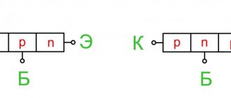
Transistor KT814B is a PNP transistor:
Here is its pinout:
In order to show the principle of its operation, we will assemble it according to a common emitter (CE) circuit:
In fact, the whole scheme looks something like this:
The blue alligator wires come from the Bat1 , and the other two alligator wires, black and red, from the Bat2 .
So, in order for the circuit to work, we set the voltage on Bat2 to power the incandescent light bulb. Since our light bulb is 6 Volt, we set it to 6 Volt.
Bat1 power supply, carefully add voltage from zero until the incandescent light comes on. And now at a voltage of 0.6 Volts
our light bulb came on
That is, the transistor “opened” and an electric current ran through the emitter-collector circuit, which made our light bulb burn. The opening voltage is the voltage drop across the base-emitter PN junction. As you remember, for silicon transistors (and our KT814B transistor is silicon, this is indicated by the letter “K” at the beginning of its name) this value is in the range of 0.5-0.7 Volts. That is, to “open” the transistor, it is enough to apply a voltage of more than 0.5-0.7 Volts to the base-emitter.
Connection circuits for NPN and PNP transistors
So, look at the two diagrams and find the difference. On the left is the NPN transistor KT815B in a circuit with an OE, and on the right is the KT814B according to the same connection circuit:
So what is the difference? Yes to power polarity! And now we can say with confidence that the PNP conduction transistor opens with a “minus”, since we apply a “minus” to the base, and the NPN conduction transistor opens with a “plus”.
You can buy bipolar transistors here.
Properties and technical characteristics of resistors
As already noted, resistors in electrical circuits and circuits perform a regulatory function. For this purpose, Ohm's law is used, expressed by the formula: I = U/R. Thus, with a decrease in resistance, a noticeable increase in current occurs. And, conversely, the higher the resistance, the lower the current. Due to this property, resistors are widely used in electrical engineering. On this basis, current dividers are created that are used in the designs of electrical devices.
In addition to the current regulation function, resistors are used in voltage divider circuits. In this case, Ohm's law will look slightly different: U = I x R. This means that as the resistance increases, the voltage increases. The entire operation of devices designed to divide voltage is based on this principle. For current dividers, a parallel connection of resistors is used, and for voltage dividers, a series connection is used.
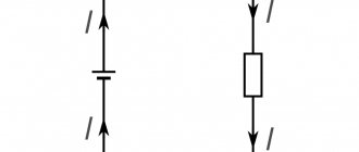
In the diagrams, resistors are displayed in the form of a rectangle measuring 10x4 mm. The symbol R is used for designation, which can be supplemented with the power value of a given element. For power above 2 W, the designation is made using Roman numerals. The corresponding inscription is placed on the diagram near the resistor icon. Power is also included in the markings on the element body. The units of resistance are ohm (1 ohm), kilohm (1000 ohm) and megaohm (1,000,000 ohm). The range of resistors ranges from fractions of an ohm to several hundred megaohms. Modern technologies make it possible to produce these elements with fairly accurate resistance values.
An important parameter of a resistor is the resistance deviation. It is measured as a percentage of the nominal value. The standard series of deviations is represented by values in the form: +20, +10, +5, +2, +1% and so on up to a value of +0.001%.
Finite rise and fall times of the pulse edge
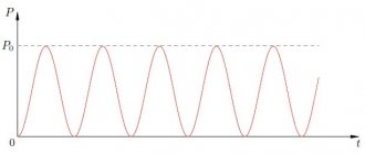
Measuring the voltage at the damper input (point Vx in Figure 1) shows that the rise and fall occur quite quickly. The voltage rises to 19.5 V and drops to 0 V in 10 ns. Is this significant? Returning to the calculation, we repeat the same calculations as above, but this time taking into account the rise time (Figure 3).
Rice. 3. Signal rise and fall
The equations below describe the energy Er1 and Er2 associated with the rise times of Tr and TON, respectively:
$$E_{r1}=CV^{2}\times \frac{\tau}{T_{r}}\times \left(T_{r}-\frac{3}{2}\tau+2\tau e^{-\frac{T_{r}}{\tau}}-\frac{\tau}{2}e^{-\frac{2T_{r}}{\tau}} \right)$$
$$V_{r1}=\frac{V}{T_{r}}\times \left[T_{r}-\tau \times (1-e^{-\frac{T_{r}}{\tau }})\right]$$
$$E_{r2}=\frac{CV_{r2}^2}{2}$$
$$V_{r2}=V-V_{r1}$$
A similar set of equations is obtained for the falling edge:
$$E_{f1}=CV^{2}\times \frac{\tau}{T_{f}}\times \left(T_{f}-\frac{3}{2}\tau+2\tau e^{-\frac{T_{f}}{\tau}}-\frac{\tau}{2}e^{-\frac{2T_{f}}{\tau}} \right)$$
$$V_{f1}=\frac{V}{T_{f}}\times \left[T_{f}-\tau \times (1-e^{-\frac{T_{f}}{\tau }})\right]$$
$$E_{f2}=\frac{CV_{f2}^2}{2}$$
$$V_{f2}=V-V_{f1}$$
The total average power dissipation is the sum of the four energies multiplied by the frequency of the voltage source.
$$P=(E_{r1}+E_{r2}+E_{f1}+E_{f2})\times f$$
However, we find that calculating the power loss in the non-ideal pulse case is a little more complicated.
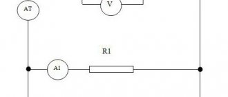
Power in series connection
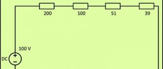
When resistors are connected in series, electric current passes through each resistance in turn. The current value at any point in the circuit will be the same. This fact is determined using Ohm's law. If you add up all the resistances shown in the diagram, you get the following result: R = 200+100+51+39 = 390 Ohms.
Considering the voltage in the circuit is 100 V, according to Ohm’s law, the current will be I = U/R = 100/390 = 0.256 A. Based on the data obtained, the power of the resistors in a series connection can be calculated using the following formula: P = I 2 x R = 0.256 2 x 390 = 25.55 W.
In the same way, you can calculate the power of each individual resistor:
- P1 = I 2 x R1 = 0.256 2 x 200 = 13.11 W;
- P2 = I 2 x R2 = 0.256 2 x 100 = 6.55 W;
- P3 = I 2 x R3 = 0.256 2 x 51 = 3.34 W;
- P4 = I 2 x R4 = 0.256 2 x 39 = 2.55 W.
If we add up the received power, then the total P will be: P = 13.11 + 6.55 + 3.34 + 2.55 = 25.55 W.
Power with parallel connection
With a parallel connection, all the beginnings of the resistors are connected to one node of the circuit, and the ends to another. In this case, the current branches out and it begins to flow through each element. According to Ohm's law, the current will be inversely proportional to all connected resistances, and the voltage value across all resistors will be the same.
Before calculating the current, it is necessary to calculate the admittance of all resistors using the following formula:
- 1/R = 1/R1+1/R2+1/R3+1/R4 = 1/200+1/100+1/51+1/39 = 0.005+0.01+0.0196+0.0256 = 0.06024 1/Ohm.
- Since resistance is a quantity inversely proportional to conductivity, its value will be: R = 1/0.06024 = 16.6 Ohms.
- Using a voltage value of 100 V, Ohm's law calculates the current: I = U/R = 100 x 0.06024 = 6.024 A.
- Knowing the current strength, the power of resistors connected in parallel is determined as follows: P = I 2 x R = 6.024 2 x 16.6 = 602.3 W.
- The current for each resistor is calculated using the formulas: I1 = U/R1 = 100/200 = 0.5A; I2 = U/R2 = 100/100 = 1A; I3 = U/R3 = 100/51 = 1.96A; I4 = U/R4 = 100/39 = 2.56A. Using these resistances as an example, a pattern can be seen that as the resistance decreases, the current increases.
There is another formula that allows you to calculate the power when resistors are connected in parallel: P1 = U 2 /R1 = 100 2 /200 = 50 W; P2 = U 2 /R2 = 100 2 /100 = 100 W; P3 = U 2 /R3 = 100 2 /51 = 195.9 W; P4 = U 2 /R4 = 100 2 /39 = 256.4 W. By adding up the powers of individual resistors, you get their total power: P = P1+P2+P3+P4 = 50+100+195.9+256.4 = 602.3 W.
Thus, the power for series and parallel connection of resistors is determined in different ways, with the help of which the most accurate results can be obtained.
Parallel connection
Parallel connection of LEDs
At any point in the series circuit, the current strength is the same. This simplifies the calculation and prevents emergency situations. If one element fails, all LEDs turn off. Therefore, damage due to increased voltage is excluded. The noted reasons explain the popularity of using this method when creating strip lamps and other designs.
Certain advantages are provided by the use of parallel connections. In this embodiment, the product retains partial functionality if one circuit is damaged. This solution ensures the same voltage at the points of connection to the power source of each branch.
Parallel connection is suitable for organizing independent control circuits. The principles of operation of New Year's garlands are based on this technology. Individual branches are connected to the power source according to the algorithm specified by the program.
You cannot use one resistor for several parallel diodes. Careful selection of resistance is due to the need to accurately regulate the current. In some situations, errors of 0.1-0.5 A cause breakdowns and a radical reduction in service life.
The actual technical characteristics of LEDs vary significantly even within the same product batch. For this reason, each circuit is protected with a separate resistor.
Resistors
Connecting in series
[Resistance of series connected resistors, kOhm
] = [
Resistance of the first resistor, kOhm
] + [
Resistance of the second resistor, kOhm
]
[Power dissipated by the first resistor, W
] = [
Resistance of the first resistor, kOhm
] * [
Current strength, mA
] ^ 2 / 1000
[Power dissipated by the second resistor, W
] = [
Resistance of the second resistor, kOhm
] * [
Current strength, mA
] ^ 2 / 1000
It turns out that from two 500 Ohm 2 W resistors you can make one 1 kOhm 4 W resistor.
Connect in parallel
[Resistance of parallel connected resistors, kOhm
] = 1 / (1 / [
Resistance of the first resistor, kOhm
] + 1 / [
Resistance of the second resistor, kOhm
])
This formula is intuitive and can be formally derived from the following considerations. At a given voltage across the resistors, each of them independently carries a current equal to the voltage divided by the resistance. The total resistance is equal to the voltage divided by the total current. In the formulas, the voltage value is happily reduced, and the given formula is obtained.
[Power dissipated by the first resistor, W
] = [
Voltage across resistors, V
] ^ 2 / [
Resistance of the first resistor, kOhm
] / 1000
[Power dissipated by the second resistor, W
] = [
Voltage across resistors, V
] ^ 2 / [
Resistance of the first resistor, kOhm
] / 1000
It turns out that from two 500 Ohm 2 W resistors you can make one 250 Ohm 4 W resistor.
Unfortunately, errors are periodically found in articles; they are corrected, articles are supplemented, developed, and new ones are prepared. Subscribe to the news to stay informed.
Practice of electronic circuit design. Electronics self-instruction manual. The art of device development. Element base of radio electronics. Typical schemes.
Application of thyristors (dinistors, thyristors, triacs). Scheme. Is. Thyristors in electronic circuits. Subtleties and features of use. Types of thyris.
Bipolar transistor. Principle of operation. Application. Types, species, category. All about the bipolar transistor. Principle of operation. Application in circuits. Properties. Cla.
Smooth adjustment of the brightness of fluorescent fluorescent lamps. Driver circuit for smoothly adjusting the brightness of fluorescent lamps. Dra.
Checking electronic elements and radio components. Check serviceability, p. How to check the serviceability of a part. Test method. What parts can be used?
RC - chain. Resistor-capacitor circuit. Resistor, capacitor. I. Calculation of RC circuits, voltage changes on the capacitor depending on time.
Power resonant filter for obtaining a sine wave from the inverter. To obtain a sinusoid from the inverter, we used a homemade power resonator.
Connection types
The main task of a transistor is to amplify the incoming signal. The problem is that any triode has only three contacts, while the amplifier itself has four poles - two for the incoming signal and two for the outgoing, that is, amplified. The way out is to use one of the transistor contacts twice: both as an input and as an output.
Read also: What is a crankshaft pulley for?
Based on this principle, three types of connection are distinguished. It is worth noting that it makes no fundamental difference what type of device is used - field or bipolar.
- Connection with a common emitter (CE) or a common source (CS). This connection diagram has the highest power amplification values for current and voltage. However, due to the Miller effect, its frequency characteristics are significantly worse. They combat this negative phenomenon in several ways: they use a connection with a common base, use a cascode connection of two transistors (a second one connected via a common base is added to the one connected via a common emitter).
- Connection with a common base (CB) or a common gate (G). The influence of the Miller effect is completely excluded here. However, this comes at a price: in this circuit there is virtually no current amplification, but there is a wide range for changing the signal frequency.
- Connection with a common collector (OC) or a common drain (OS). This type of connection is often called an emitter or source follower. This is the “golden mean” between the two previous types of circuits: frequency characteristics and amplification power in terms of current and voltage are somewhere in the middle between the first two.
All three connection types described above are used depending on what goals the designers are pursuing.