The quality of work when using inverter equipment is largely determined by the welding arc, its stability and reliability. However, surges and drops in the mains voltage can lead to a failure, and the arc spontaneously turns off. To avoid such situations and ensure stable operating conditions, a special device is used - an oscillator for the inverter. It is connected in parallel to the main device, and its function is to directly excite the arc and maintain it during the entire welding process.
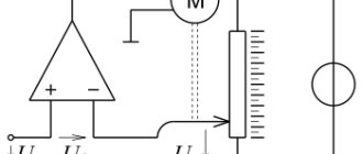
Electrical circuit of the oscillator
Schemes and designs of welding oscillators may differ based on operating conditions and frequency of use.
Typically, these devices are connected in two ways:
- Consistently. This connection allows you to weld aluminum workpieces.
- Parallel. Used when working with stainless steel and for short-term welding.
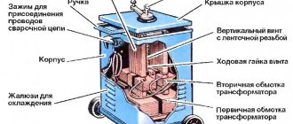
A typical circuit consists of the following electrical components:
- Standard single-circuit spark gap design. This part is essentially a generator and ensures the formation of damped oscillations. It consists of a capacitor and inductors connected in parallel. Tungsten electrodes serve as contacts.
- There are two chokes, also made on the basis of inductors.
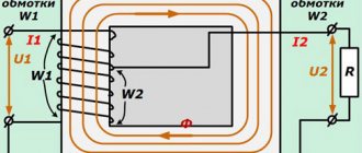
- Powerful step-up transformer. Converts standard mains voltage up to 6000 V and frequency up to 250 kHz.
- Transformer installed at the output. Transfers the generated voltage to the welding inverter circuit.
- Control circuit parts. This includes a stabilizer, start-up control elements, and a feedback loop with a current sensor.
- Security system elements. Made in the form of safety circuits that protect the circuit from overloads, and the worker himself from electric shock.
Where are the devices used?
Oscillators are widely used in the processing of non-ferrous metals. If you need to make a strong, neat seam, the oscillator will solve the problem as quickly as possible - by exciting a lightning arc and starting the welding process. This is much simpler and more effective than striking the product with an electrode.
An oscillator is indispensable when you need to make a precise seam. The master attaches the end of an iron needle to the nearest edge of the joint, lowers the mask onto his face, then presses a button and an arc appears. This significantly reduces the complexity of processing products in order to remove traces of contact with electrode elements.
The welding oscillator is also used for processing thin sheets of various alloys. The inverter current in them is set to minimum levels; minor adjustments to the electrode ends from the weld pools are fraught with failures and gaps in the arc. The oscillator allows you to stabilize low-current electric welding processes.
Interaction with the inverter
The principle of operation of the equipment that stabilizes the operation of the inverter is to additionally supply high voltage to the electrode. It arrives periodically, along with the main output voltage of the welding unit itself. The voltage comes in the form of pulses with characteristic amplitude modulation. Their parameters can reach 6 kV, and the frequency is in the range of 150-500 kHz.
The duration of the generated pulses is insignificant, so they have a very low duty cycle, quite sufficient to obtain the required power - up to 300 W. Their impact leads to the formation of a short-term electrical breakdown between the part and the electrode, increasing the reliability of the contact. The oscillator starts when the electrode approaches the metal by approximately 5 mm. Under the influence of electrical impulses, the air gap is ionized, after which an instantaneous discharge occurs.
Operating principle
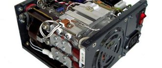
All installations in this category are integrated inside the equipment circuit in the area between the rectifier element, transformer station and welding electrode holder. As a result, contact is created and the operation of the installations is stabilized. Most installations have a similar design of:
- rectifier;
- work blocks;
- power supply;
- main working node;
- valves;
- transformer devices;
- voltage sensor.
The main task of the device generating pulses is to modernize the incoming voltage, increase V, frequency, and reduce the duration of the pulse flash to a second interval.
Features of the scheme implementation:
- Start (press the corresponding button).
- The rectifying device stabilizes the strength of the input current and makes it unidirectional.
- Capacitor working parts accumulate discharge voltage.
- When the current is released, it flows into the oscillatory motion circuit (its main part is made up of transformer windings), and the force V increases.
- The pulse is released and the gas supply valve opens.
- The impulse force triggers the discharge.
- As the current charge passes through the circuit, the pulse stops. The seam connection will be created on the posts.
After the arc has died down, the oscillator purges the burners with argon gas for a few more seconds. After the seam has cooled, the work can be considered completed.
Types of oscillators
The welding oscillator can only be used as an additional device. By itself, it cannot provide a working process, due to its low power and the inability to independently connect and melt metals. The main purpose of the device is to ignite the arc and maintain its stable state without contact of the electrode with the metal surface.
This result was achieved by generating high voltage at high frequency, capable of breaking through the air space between the metal and the electrode. A zone of ionized air is created, through which the main welding current then begins to flow.
Depending on the operating modes, all oscillators can be divided into the following groups:
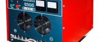
- Continuous devices (Fig. 1). Capable of delivering current with voltages of up to 6000 volts and a frequency of about 250 kHz. This additional potential combines with the main welding current to instantly ignite the arc at a certain distance from the workpiece. High frequency ensures stability, regardless of the inverter current parameters. Due to the low power, the additional current is completely safe for the welder. The device is connected to the inverter using a parallel or serial circuit. The latter option is used more often and does not require additional high voltage protection.
- Pulse oscillators (Fig. 2). Very convenient when performing welding work with alternating current. These devices have the ability to constantly maintain an arc with changing polarity of electricity. They easily ignite the arc in the absence of any contact between the electrode and the workpiece. In general, pulsed instruments have some advantages over continuous oscillators.
- Devices using storage capacitors. These components are installed in a general circuit and subsequently ensure the operation of the device in charge-discharge mode. The capacitors are filled with energy using a charging module. At the moment of operation, the energy of the charged capacitors is transferred to the arc. They are then disconnected from the discharge circuit and automatically connected to the charging module. If there is a threat of arc interruption, the capacitors are switched to the working circuit of the welding equipment.
Rules for using equipment
In order to safely and comfortably operate the oscillator during welding operations with any non-ferrous metals or stainless steel, you should adhere to certain rules for operating the equipment:
Rules for using welding equipment
- It is allowed to use an oscillator for an inverter, working both outdoors and indoors with proper ventilation;
- During precipitation and high humidity, it is recommended not to use the equipment, or to use it limitedly under a canopy;
- The ambient temperature acceptable for turning on the welding equipment and oscillator is -10 – +40 degrees Celsius;
- It is forbidden to supply power to the welding oscillator if the air is saturated with moisture above 98 percent;
- The optimal atmospheric pressure for safe welding with an oscillator is 86-106 kPa;
- In dusty rooms or where there is severe contamination with gases and caustic vapors, intensive wear of the equipment occurs;
- Before starting welding work, it is necessary to reliably ground the oscillator and welding inverter to avoid electric shock;
- Power is supplied to the devices only when the correct connection of the equipment has been checked;
- When the oscillator is turned on, it is prohibited to remove the protective casing of its electrical circuit and carry out work without it;
- Carbon deposits and dirt are regularly removed from the surface of the spark gap.
How to make the device yourself
If you have certain knowledge and practical skills in working with electronics, making an oscillator for an inverter yourself will not be difficult. There may be several options for the device, therefore, when choosing the most suitable scheme, it is necessary to determine the operating conditions and other initial data.
Typically, the following factors are taken into account:
- Purpose of the equipment. It is advisable to determine as accurately as possible what material you will have to work with. Each metal has its own characteristics, which are taken into account when drawing up the diagram.
- Basic parameters of current and voltage: alternating or direct, mains voltage characteristics, etc.
- The amount of permissible electrical power. Determined by the input power of conventional circuits, not exceeding 250 W. An increase in this indicator will inevitably entail an increase in the cost of parts and the entire device as a whole.
- The value of the generated secondary voltage is usually no more than 3 kW.
In the household, welding of aluminum blanks is most often required. Therefore, you need to choose a scheme that most fully provides this type of work. First you need to choose a suitable transformer that can increase the voltage from the usual 220 to 3000 V.
At the next stage, a spark gap is installed that allows a spark to pass through. Next, an oscillatory circuit is included in the circuit. It must contain a blocking capacitor that ensures the generation of high-frequency pulses. With its help, the device acquires all the necessary indicators. The welding arc is given stability and its ignition is greatly simplified.
Upon completion of assembly, the functionality of the finished device is checked. First, a start-up is performed, causing the arrester to start and create high-frequency pulses using a step-up transformer. After the arc occurs, a powerful magnetic field appears, which enters a coil with a winding of thick wire. Here this field is converted into an electric current, connected by the plus to the torch, and by the minus to the workpiece. Gas enters the same torch, passing through a special valve, and welding begins.
Diagnostics of a homemade inverter and its preparation for operation
Making an inverter welding machine is half the battle
An equally important task is to prepare it for work, during which the correct functioning of all elements is checked, as well as their settings
The first thing you need to do when checking a homemade welding inverter is to apply a voltage of 15 V to the PWM controller and one of the cooling fans. This will allow you to simultaneously check the functionality of the controller and avoid overheating during such a test.
Checking the output voltage with a tester
After the capacitors of the device are charged, a relay is connected to the electrical supply, which is responsible for closing the resistor. If you apply voltage directly to the resistor, bypassing the relay, an explosion may occur. After the relay operates, which should happen within 2-10 seconds after applying voltage to the PWM controller, you need to check whether the resistor has shorted.
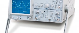
When the relays of the electronic circuit operate, rectangular pulses should be generated on the PWM board and supplied to the optocouplers. This can be checked using an oscilloscope. The correct assembly of the diode bridge of the device also needs to be checked; for this, a voltage of 15 V is applied to it (the current should not exceed 100 mA).
The transformer phases may have been incorrectly connected when assembling the device, which can lead to incorrect operation of the inverter and the generation of strong noise. To prevent this from happening, the correct phase connection must be checked using a dual-beam oscilloscope. One beam of the device is connected to the primary winding, the second to the secondary. The phases of the pulses, if the windings are connected correctly, should be the same.
Using an oscilloscope to diagnose an inverter
The correct manufacturing and connection of the transformer is checked using an oscilloscope and connecting electrical devices with different resistances to the diode bridge. Based on the noise of the transformer and the readings of the oscilloscope, they conclude that it is necessary to improve the electronic circuit of the homemade inverter apparatus.
To check how long you can continuously work on a homemade inverter, you need to start testing it from 10 seconds. If the device’s radiators do not heat up during operation for such a duration, you can increase the period to 20 seconds. If such a time period does not negatively affect the condition of the inverter, you can increase the operating time of the welding machine to 1 minute.
DIY plasma torch
When making a plasma cutter from a welding inverter with your own hands, the most difficult part of the work is the production of a high-quality cutting head (plasma torch).
Tools and materials
If you make a plasma cutter with your own hands, it is easier to use air as a working fluid. For production you will need:
- a handle in which the cable and air supply tube should fit;
- plasma cutter torch start button;
- insulating sleeve;
- plasma cutter torch electrode;
- air flow swirl device;
- a set of nozzles of various diameters for cutting metals of various types and thicknesses;
- protective tip against splashes of liquid metal;
- a limiting spring to maintain the same gap between the plasma cutter torch nozzle and the metal being cut;
- chamfering attachments.
Plasma cutter consumables in the form of nozzles and electrodes should be purchased at a welding equipment store. They burn out during the cutting and welding process, so it makes sense to purchase several pieces for each nozzle diameter.
The thinner the metal to be cut, the smaller the plasma cutter torch nozzle hole should be. The thicker the metal, the larger the nozzle opening. The most commonly used nozzle is the one with a diameter of 3 mm; it covers a wide range of thicknesses and types of metals.
Assembly
The plasma cutter torch nozzles are attached with a clamping nut. Directly behind it there is an electrode and an insulating sleeve, which does not allow an arc to occur in an unnecessary place in the device.
Then there is a flow swirler that directs it to the desired point. The entire structure is placed in a fluoroplastic and metal case. A pipe for connecting an air hose is welded to the outlet of the tube on the plasma cutter torch handle.
Transformer based cutter
Like other components of the system, the power supply is assembled or modified with your own hands. Detailed instructions help you easily cope with this task.
Device diagram
The electrical circuit of the device includes the following components:
- welding transformer with rectifier;
- start relay;
- oscillator;
- a resistor that reduces the pilot arc voltage;
- start button;
- a contactor that deactivates the initial arc;
- compressor with controls.
A correctly compiled diagram should display all elements, regardless of their location.
What details will be needed
In addition to the welding inverter, to create the machine you will need:
- Holder with replaceable rod. When the current is up to 100 A and the thickness of the workpiece is up to 5 cm, the element is made of copper. The holder of a more powerful unit is equipped with channels for liquid cooling. To ignite the arc, leave a distance of 2 mm between the nozzle and the electrode. The main rod is made movable.
- PTFE insulator. Due to rapid wear, the part is replaceable.
- Housing with nozzle.
- Cables: power and for igniting the pilot arc.
- Hoses. In liquid-cooled units, the bare wire is located in the tube that supplies water to the torch. You will also need a separate hose to remove gas to the nozzle.
Plasma cutter assembly
Work begins with remaking the welding transformer. The number of turns of the winding is selected taking into account the future characteristics of the equipment and the parts being cut.
With a sheet thickness of up to 1.2 cm, a current of 50 A and an open circuit voltage of 20 V, set the following values:
- core cross-section - 107 mm²;
- the number of turns of the primary winding is 225, the secondary is 205.
After remaking the transformer, other elements are connected:
- Compressor with a capacity of 140-190 l per minute. The pressure generated by the unit must be more than 4.5 bar.
- Cables and hoses for connecting components. The cross-section of the supply wire depends on the power of the plasma cutter. At a current of 50 A it is 6 mm². The wire cross-section for the pilot arc is 1.5 mm². The recommended diameter of the air hose is 1 cm.
- Oscillator. When creating a plasma cutter from a transformer, you can use a car electronic ignition system as this block.
The air hose is connected to the compressor outlet. The start key wire is connected to the control unit.
Features of use
When working with a cutter from a transformer from a semi-automatic welding machine, carefully follow safety rules, which is explained by the influence of the following harmful factors:
- Melt splash. Under the influence of plasma, the metal is heated to extreme temperatures. The air flow blows it out of the cut line. Splashing some materials will cause them to catch fire. Contact of the melt with human skin leads to deep burns. Therefore, the plasma jet is directed in the direction opposite to the welder and flammable materials.
- Dust and air pollution with harmful gases. During plasma cutting, metal begins to burn. Smoke is dangerous to the human respiratory system. Therefore, a hood is installed above the desktop. The master puts on a respirator.
- Bright light. The plasma torch is a powerful generator of ultraviolet radiation, which causes burns to the retina of the eye. Therefore, the carver puts on a protective mask and equips the work area with a mobile shield.
- Temperatures. The edges of the resulting blanks retain heat for a long time. You can touch them only with gloves after the parts have cooled.
Advantages and disadvantages
The advantages of using plasma equipment over other cutting methods include:
- ability to work with all metals and alloys;
- high performance of the device;
- increased precision of impact, helping to obtain an even cut without sagging or drips;
- no need to preheat parts;
- refusal to use explosive gases - methane or oxygen.
The disadvantages of plasma cutting are:
- the complexity of assembling a home-made device, the high cost of ready-made installations;
- the need to organize a separate control unit for each operator;
- cutting angle no more than 50°;
- increased noise level from operating equipment.