In order for LED lamps to work as brightly and efficiently as possible, special modules are used - drivers. Anyone can assemble a driver circuit for LEDs on their own, if, of course, they have knowledge of electrical engineering. The purpose of the device is to convert the alternating voltage flowing in the network into direct (reduced) voltage. But before you start assembling, you need to decide what requirements are imposed on the device - analyze the characteristics and types of devices.
What are drivers for?
The main purpose of the drivers is to stabilize the current that passes through the LED. Moreover, it is necessary to take into account that the current strength that passes through the semiconductor crystal must be exactly the same as that of the LED according to the passport. This ensures stable lighting. The crystal in the LED will last much longer. To find out the voltage required to power the LEDs, you need to use the current-voltage characteristic. This is a graph showing the relationship between supply voltage and current.
If you plan to illuminate a residential or office space with LED lamps, then the driver must be powered from a household AC network with a voltage of 220 V. If LEDs are used in automobiles or motorcycles, you need to use drivers powered by a constant voltage, value 9-36 V. V In some cases (if the LED lamp is of low power and is powered from a 220 V network), it is possible to remove the LED driver circuit. If the device is powered from the network, it is enough to include a constant resistor in the circuit.
Inside look: 13 LED lights and a bottle of rum. Part 3
Hello again, my little entrails lovers!
We have finally reached the final part of the story about LED lamps, in which we will look at 4 lamps in the E27 base, and also sum up the final results of this protracted story.
The last two parts are here and here.
Let’s not drag out our story about lamps and get straight to the main thing – the insides of patients, LED lamps from ASD
,
Gauss
and
Supra
.
LED lamps in E27 base: spacious housing = the key to a successful lamp
As we remember from the first part, all LED lamps in the E27 base showed decent characteristics in terms of ripple levels, not exceeding 1%.
It is quite natural that such a driver requires a fairly spacious housing to accommodate it, if only because it has more components than a capacitor ballast. However, using the example of a light bulb from Gauss, we could verify that even in a GU5.3 housing it is possible to compactly place a ripple-free driver made using transformerless technology. Well, let's see what's inside the first guinea pig from today's list - a lamp from the manufacturer ASD
.
The cover can be removed quite easily, almost with bare hands, which, apparently, is a manufacturing defect/defect, since there is glue on the back side. In this case, the LED assembly is attached directly to the metal body of the lamp, but the heat sink is organized only along the outer ring, which, as the reader probably already understands, is not good. For example, in the same E14 and GU5.3 lamps, the assembly is in contact with the heat-dissipating body over the entire area.
It is easy to see that the provided volume is used freely, without much effort to minimize the size of the driver. The electrical circuit is shown in the image below. It is made according to the transformerless step-down topology that has already become classic for lamps with large bodies. The arrangement of 28 LEDs is sequential, with SMD resistors (?) added here and there. If anyone knows why this was done, please write in the comments.
Individual LEDs are packaged in oblong housings and soldered between copper contacts; ASD also uses similar SMD components in GU5.3 lamps. In the figure below, the boundary between two such contacts is clearly visible (dark gray area). The size of the light-emitting element itself is 253 by 83 microns.
Next in line will be two lamps from Gauss
power 6.5 and 12 W, respectively. Despite the similarity in many respects, these LED lamps also have some differences, for example, the driver, and, most interestingly, different LEDs inside.
The scattering bulb is very successfully attached to the body of the lamp - you have to sweat a lot to break it out (yes, break it out!) from there, because the Gauss company does not spare glue and sealant for light bulbs. Thus, you can absolutely safely use these lamps in rooms with high humidity.
However, Gauss light bulbs have the same problem as ASD; the metal heat dissipator in the lamp body is connected to an aluminum substrate on which the LEDs are attached only in a relatively small ring around them.
Of course, from the point of view of thermophysicists, this is a solution. maybe it makes sense, but still... About maintainability
Gauss took an interesting approach to this aspect. Of course, I will not claim that the lamps from this manufacturer are completely repairable, while the others are not. However, the engineers of this company obviously worked on both the assembly and disassembly of the lamp. The LED assembly on an aluminum plate is not tightly soldered to the driver, as we can see everywhere, but is connected using a simple connector. If you really want, you can gut the light bulb, take out the driver and LED assembly, replace the necessary components (capacitors, for example) and put the driver and diodes back together, or at least use a good, “non-blinking” driver for your purposes! The driver itself is made using transformerless technology. The LED blocks (12 in total, each in a separate SMD housing) are connected in series.
The sapphire substrate of the light-emitting chips is structured, like that of ASD - isn’t that the same plant that produces them, the substrates?! LEDs have a emitting surface of as much as 283 by 140 square micrometers, which is one of the largest indicators among the lamps presented.
Let us now turn to a 12 W light bulb. Fundamentally, it is not much different from a 6.5 W lamp: a similar driver, albeit with its own characteristics, the same plastic bulb with a metal diffuser ring inside, similar LED modules, albeit in larger quantities; however, only this lamp has the driver filled with a special compound.
About uploading the driver
The dear LampTester has already disassembled a lamp from Gauss. However, I beg to differ with the author in terms of organizing the heat removal of this lamp. The electrical circuit and heat sink are designed correctly: the inductor and one of the capacitors are placed closer to the hot zone of the lamp, which is surrounded by a metal rim to dissipate heat, while the more sensitive elements are located in the “cold part”. In addition, the filling should increase heat exchange with the metal shell, because, as you know, air is a good heat insulator (remember the old window frames). We have already seen a similar fill when analyzing a light bulb from Optogan and SvetaLED.
There were some problems with the driver's electrical circuit, so the block where the coil should be located was left with a question mark. On the one hand, the control chip used implies a transformerless driver, but on the other hand, the inductor used has 3 pins on the board, which would seem to tell us about a driver based on a flyback converter, but the resistances between the contacts/legs of the coil are only 1.7, 5.8 and 6.2 Ohm, which should not fit into the galvanic isolation circuit in this driver.
A 12 W light bulb contains as many as 32 LED housings. True, the LEDs themselves have a slightly different size: 275 by 148 microns versus 283 by 140 microns for a 6.5 W bulb and an excellent arrangement of contact tracks. At first glance, the LEDs are almost identical, but I still wonder what this could be connected with: different batches of LEDs or are they really different for lamps of different power? Let me remind you that lamps of the same color temperature were used under the knife - 2700K.
LED modules from the same company may differ - what a twist!
And the last in this class, a light bulb from Supra
. The light bulb is difficult to open, which means that the seal is completely fine: enough sealant has been poured. The neutral line contact is not soldered to the base itself, but is only pressed against it, as we said in the previous part, this method of fixation is not the most reliable - it is quite difficult to remove the base, but it is possible!
But what really surprised me was the LED assemblies mounted on a completely flexible PCB instead of an aluminum substrate, which in turn is connected with thermal paste to a heat-sinking housing. As a result, another positive point was the presence of a full-fledged heat dissipator, and not a ring, like the three lamps discussed above.
The driver of the presented lamp is based on technology... Yes, a similar story as with the Gauss 12 W lamp. It is difficult to understand by simple ringing what a choke with three contacts on the board is. Therefore, in the final table, although these two drivers will appear under the “flyback converter”, they are most likely made using a transformerless step-down topology. Although conscious readers sometimes send useful links, from which it follows that the microcircuit used implies a transformerless driver.
Now let's make some analogies. The LEDs are connected in series-parallel, just like an ASD lamp (ring number one).
The name of the control chip is BP2822 from the BPSemi company.
If we look at the light-emitting elements themselves, it turns out that in terms of dimensions (251 by 83 versus 253 by 83 microns), the location of the contact pads and the microstructure, they are completely identical to the LEDs in the ASD lamp (bell number two). Yes, they are packaged in a case of two pieces, but often they are packaged in different cases: one, two, three, four, and so on. So it is quite possible to assume that the ASD and Supra bulbs are filled with LED modules from the same manufacturer. With equivalent filling (driver + LEDs), similar lighting performance indicators, it is not surprising that the retail cost of lamps is practically the same - about 250-270 rubles (August-September 2015).
Deja vu? Yes, completely identical to the ASD lamp
Final conclusions
Well, after such a long and sometimes not always successful, but sometimes extremely intriguing testing of LED lamps, as well as a journey through their inner world, it remains to sum up the final results.
- About appearance.
As we can see, even those LED lamps that seem sealed, in fact, are not. Therefore, my dear reader and buyer, before purchasing them for rooms with high humidity, be sure to check the mounting of the light diffuser! - About drivers.
The drivers of all lamps are divided into two large camps: capacitor ballast (strong ripple factor up to 10-15%) and transformerless driver (Kp<1%). Typically, an advanced driver is installed in lamps with an E27 socket, while almost all lamps with an E14 and GU5.3 socket are equipped with a capacitor ballast, which gives a strong ripple factor. A pleasant exception was the Gauss GU5.3 lamps, which have a compactly packaged transformerless driver on board. However, the pulsations of these lamps have a very high frequency - several hundred Hz. - About thermal contact and thermal sink.
Many manufacturers sin by poor-quality installation of the LED assembly into the lamp, as a result of which the thermal contact between the aluminum or textolite substrate and the heat dissipator/radiator is disrupted, which, whatever one may say, leads to premature failure of the most sensitive component - light-emitting diodes. Most of the complaints arose against the Pulsar company. Plus, some people manage to glue assemblies onto some analogue of gel-like tape (for example, as Wolta does). - About substrates for LED assemblies.
Some manufacturers place LED modules on a textolite rather than aluminum substrate - a very interesting solution that reduces the weight and dimensions of the lamp, but requires additional testing and verification, although I personally really like it! - About LEDs and their manufacturing technologies.
Based on the type of structuring of the sapphire substrate used, the lamps were divided into three types. Let’s call them conventionally: “shield”, “star” and “rings”:
Modern technologies for texturing sapphire substrates for LEDs in comparisonSome lamps are confusingly similar in appearance to the LEDs used, which raises serious questions for manufacturers. For example, with some degree of confidence we can say that the LEDs in the lamps of ASD and Supra companies were produced at almost the same plant.
- About the versatility of production.
As the practice of opening lamps has shown, sometimes the versatility of LED lamp production is not a determining factor. So, for example, seemingly the same lamps from the Gauss company, differing only in power, have both different drivers and different LEDs that bear little resemblance to each other. - About luminous flux, power and a little about heat transfer.
If we collect all the geometric characteristics and the associated specific characteristics of the lamps in one table (neglecting losses in the driver), we will see that the specific luminous flux and power dissipation are inversely related. Some manufacturers, such as Supra, produce a stunning 1500 lm/mm2, but this comes at the cost of 22 watts of dissipated energy per mm2. This is where the time comes to compromise and pay for the “analogue” 100W light bulb. Unfortunately, this is a difficult task to achieve without redistributing the thermal energy released by the LEDs and, accordingly, using special radiators and diffusers.
NB:
The author of the article is not a professional electrical engineer, so if you notice an error or omission in the diagrams, text or anywhere else, please write to me in a PM.
PS:
There are at least two confirmed manufacturers of control chips: Monolithic Power and BPSemi. Also some reference designs from Dialog Semiconductor (together with iWatt)
PPS:
All diagrams are drawn in the free (open-source) software package QUCS, which toster helped me find.
UPD:
Commentary from D3 brought interesting information about interference and methods of protection - here.
Full list of published articles “A Look from the Inside” on Habré and GT:
Opening the Nvidia 8600M GT chip, a more detailed article is given here: Modern chips - a look from the inside A look from the inside: CD and HDD A look from the inside: LED light bulbs A look from the inside: LED industry in Russia A look from the inside : Flash memory and RAM A look from the inside: the world around us A look from the inside: LCD and E-Ink displays A look from the inside: digital camera matrices A look from the inside: Plastic Logic A look from the inside: RFID and other tags A look from the inside: PhD studies at EPFL. Part 1 A look from the inside: postgraduate studies at EPFL. Part 2 A look from the inside: the world around us - 2 A look from the inside: the world around us - 3 A look from the inside: the world around us - 4 A look from the inside: 13 LED lamps and a bottle of rum. Part 1 A look from the inside: 13 LED lamps and a bottle of rum. Part 2 A look from the inside: 13 LED lamps and a bottle of rum. Part 3 A look from the inside: IKEA LED strikes back A look from the inside: are Filament lamps really that good?
and 3DNews: Microview: comparison of displays of modern smartphones
Secondly
, in addition to the blog on HabraHabr, articles and videos can be read and watched on Nanometer.ru, YouTube, and also Dirty.
Sometimes you can read briefly, and sometimes not very much about science and technology news on my Telegram channel - you are welcome;)
Driver settings
Before purchasing a device or making it yourself, you need to familiarize yourself with what its main characteristics are:
- Rated current consumption.
- Power.
- Output voltage.
The voltage at the output of the converter directly depends on the chosen method of connecting the light source and the number of LEDs. The current has a direct relationship with the brightness and power of the elements.
The converter must provide a current at which the LEDs will operate at the same brightness. The PT4115 LED driver circuit is implemented quite simply - it is the most common voltage converter for use with LED elements. You can literally make a device based on it “on your knees.”
How does an LED floodlight work?
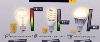
Externally, an LED floodlight works in the same way as its counterpart with an incandescent lamp. It just consumes less electricity and is more durable. In fact, it emits light based on completely different physical principles. “Ilyich’s light bulb” - the basis of outdated lamps - shines using a hot filament. To do this, you need to heat it up, and the efficiency in this process is only 3-4%, like the first steam locomotives. The remaining 96-97% of energy goes into heat.
Appearance of LED spotlight
LED is another matter. Here, light emission is associated with physical processes occurring in the pn junction of a diode made of a special semiconductor (usually gallium arsenide), and does not depend on the degree of heating. The efficiency of such a light source reaches 60% (according to manufacturers). The rest goes into heat (the Joule-Lenz law cannot be circumvented), so measures have to be taken to remove heat. Otherwise, the lifespan of the LEDs will drop sharply.
Driver power
The power of the device is the most important characteristic. The more powerful the driver, the greater the number of LEDs that can be connected to it (of course, you will have to carry out simple calculations). A prerequisite is that the driver power must be greater than that of all LEDs in total. This is expressed by the following formula:
Р = Р(св) x N,
where P, W – driver power;
P(sv), W – power of one LED;
N – number of LEDs.
For example, when assembling a driver circuit for a 10W LED, you can safely connect LED elements with a power of up to 10 W as a load. You definitely need to have a small power reserve - about 25%. Therefore, if you plan to connect a 10 W LED, the driver must provide a power of at least 12.5-13 W.
How to disassemble an LED spotlight with glued glass
The design of many lamps is such that you can get to the remaining components only by removing the glass. In expensive spotlights, the frame with glass is often bolted. In most economy-class devices, the glass is glued to the reflector compartment with a sealing compound, and it can be difficult to remove.
How to remove glass from an LED spotlight
If you need to disassemble a device with glued glass, as a first step you can try to carefully remove the sealant (at least part) with a sharp knife or small screwdriver. If this doesn’t help, you should try to warm up the frame around the perimeter with a hair dryer and pry it off with a sharp object. If you fail here too, there is another way.
Screw on the back of the spotlight housing
On the back of most spotlights there is a screw, the purpose of which is most likely a plug to seal the internal space after assembly. Sometimes it is enough to unscrew this screw so that the pressure inside the lamp is equal to atmospheric pressure (a vacuum can occur due to cooling of the air inside the device). After this, you can try to repeat the operation with warming up and prying up the edge. If this doesn’t work, then you need to find a screw with the same thread, but longer. This screw must be screwed into place until it stops. After this, you need to try again to warm up the joint, slowly tightening the screw. And when the glass moves, pry it in this place and continue heating along the perimeter, carefully tearing it off along the remaining length.
LED colors
Be sure to take into account what color the LED emits. This determines what voltage drop they will have at the same current strength. For example, with a supply current of 0.35 A, the voltage drop for the red LED elements is approximately 1.9-2.4 V. The average power is 0.75 W. A similar model with green color will already have a drop in the range of 3.3-3.9 V, and a power of 1.25 W. Therefore, if you use a 220V LED driver circuit with conversion to 12V, you can connect a maximum of 9 elements with green color or 16 with red color to it.
Driver types
In total, there are two types of drivers for LEDs:
- Pulse. With the help of such devices, high-frequency pulses are created in the output part of the device. Operation is based on the principles of PWM modulation. The average current value depends on the duty cycle (the ratio of the duration of one pulse to the frequency of its repetition). The output current changes due to the fact that the duty cycle fluctuates in the range of 10-80%, and the frequency remains constant.
- Linear - a typical circuit and structure are made in the form of a current generator using transistors with a p-channel. With their help, you can ensure the smoothest possible stabilization of the supply current if the input voltage is unstable. They are cheap, but have low efficiency. During operation, a large amount of heat is generated, so it can only be used for low-power LEDs.
Pulse ones have become more widespread, since their efficiency is much higher (can reach 95%). The devices are compact and the input voltage range is quite wide. But there is one big drawback - the high influence of various types of electromagnetic interference.
Advantages and disadvantages
It’s hard not to be interested in dimmable lamps – the ability to change the lighting intensity looks very tempting. Before you buy such lamps or fixtures, evaluate their advantages and disadvantages.
Pros of a dimmable lamp:
- Selecting the operating mode allows you to use the lamp for both intense lighting and light illumination in the evening.
- Dimmable LED lamps last longer than non-dimmable ones. If the latter are connected to a dimmer, they will quickly burn out due to exposure to extreme loads that their stabilizers cannot withstand.
- It can change the temperature of light transmission, which allows you to change the perception of space.
- Does not emit infrared and ultraviolet rays. Thanks to this, objects, fabrics, furniture upholstery, wallpaper and other things that are exposed to lighting do not burn out.
- Can be used for room zoning. To do this, individual lamps are connected to a dimmer and, by changing the brightness of the lighting, illuminate the desired areas of the room.
Dimmer lamps have much fewer disadvantages
- The main disadvantage is the high cost. Moreover, both the lamp itself and the control switch are expensive.
- There may be difficulties with choosing lamps and dimmers - they must match each other and be compatible. Some manufacturers produce lamps that are compatible only with dimmers of their own production.
- They can interfere with electrical appliances, sometimes flickering, humming and crackling (if the lamps are of low quality).
What to look for when purchasing?
It is imperative to purchase a driver when choosing LEDs. On PT4115, the LED driver circuit allows for the normal functioning of the lighting system. Devices using PWM modulators built using single-chip circuits are mostly used in automotive applications. In particular, for connecting backlights and headlights. But the quality of such simple devices is quite low - they are not suitable for use in household systems.
Dimmable Driver
Almost all converter designs allow you to adjust the brightness of LED elements. With these devices you can do the following:
- Reduce light intensity during the day.
- Hide or emphasize certain interior elements.
- Zoning the room.
Thanks to these qualities, you can significantly save on electricity and increase the life of the elements.
Types of dimmable drivers
Types of dimmable drivers:
- Connect between the power supply and the light source. They allow you to control the energy that goes to the LED elements. The design is based on PWM modulators with microcontroller control. All energy goes to the LEDs in pulses. The energy that goes to the LEDs directly depends on the length of the pulses. Such driver designs are used mainly for operating modules with stabilized power supply. For example, for ribbons or tickers.
- The second type of device allows you to control the power supply. Control is carried out using a PWM modulator. The amount of current that flows through the LEDs also changes. As a rule, such designs are used to power those devices that require stabilized current.
It is necessary to take into account the fact that PWM regulation has a bad effect on vision. It is best to use driver circuits to power LEDs in which the current is regulated. But here’s one caveat: depending on the current value, the glow will be different. At a low value, the elements will emit light with a yellow tint; at a higher value, it will emit a bluish tint.
LED power supply circuit based on a capacitor divider
Unfortunately, the design of cheap 220V LED lamps from China does not provide either a linear or a pulse stabilizer. Motivated by the exceptionally low price of the finished product, the Chinese industry was able to simplify the power supply circuit as much as possible. It is not correct to call it a driver, since there is no stabilization here.
The figure shows that the electrical circuit of the lamp is designed to operate from a 220V network. The alternating voltage is reduced by the RC circuit and supplied to the diode bridge. Then the rectified voltage is partially smoothed by a capacitor and is supplied to the LEDs through a current-limiting resistor. This circuit does not have galvanic isolation, that is, all elements are constantly at high potential.
As a result, frequent sags in the mains voltage lead to flickering of the LED lamp. Conversely, an excessive network voltage causes an irreversible aging process of the capacitor with loss of capacity, and, sometimes, causes its rupture. It is worth noting that another serious negative side of this scheme is the accelerated process of LED degradation due to unstable supply current.
Which microcircuit should I choose?
If you don’t want to look for a ready-made device, you can make it yourself. Moreover, make calculations for specific LEDs. There are quite a lot of microcircuits for making drivers. All you need is the ability to read electrical diagrams and use a soldering iron. For the simplest devices (power up to 3 W), you can use the PT4115 chip. It's cheap and very easy to get. The characteristics of the element are:
- Brightness adjustment.
- Supply voltage – 6-30 V.
- Output current – 1.2 A.
- The permissible error when stabilizing the current is no more than 5%.
- Load cut-off protection.
- Conclusions for dimming.
- Efficiency – 97%.
Designation of microcircuit pins:
- SW – connection of the output switch.
- GND – negative terminal of power and signal sources.
- DIM – brightness control.
- CSN – input current sensor.
- VIN is the positive terminal connected to the power supply.
Body parts
Arduino controller board. Such repairs help restore the functionality of humidifiers in most cases. The transistor is installed on the radiator to remove excess heat.
Do not touch the housing with wet hands. And here's another thing!
Moisture is absorbed by the air that passes through the membrane, and as a result, the air humidity in the room increases and the temperature decreases. When the water in the humidifier runs out, the float moves down and the field is captured by the sensitive element of the electronic board. An air humidifier traditionally consists of a drive roller, a control panel, louvers, a water tank and water level indicator, a coupler, an annular membrane and its motor, a centrifugal fan and its motor, an internal power cord and a filter.
The effect of such devices is similar to wet cleaning.
When the tester does not respond, use a professional to check the humidifier. During its operation, such a device saturates the air with moisture and cleans it of various impurities and harmful substances. Humidifier does not produce steam
Driver circuit options
Device options:
- If there is a power source with a constant voltage of 6-30 V.
- Powered by an alternating voltage of 12-18 V. A diode bridge and an electrolytic capacitor are introduced into the circuit. Essentially, a “classical” bridge rectifier circuit with cutting off the variable component.
It should be noted that the electrolytic capacitor does not smooth out voltage ripples, but allows you to get rid of the variable component in it. In equivalent circuits (according to Kirchhoff's theorem), the electrolytic capacitor in the alternating current circuit is a conductor. But in a DC circuit it is replaced by a break (there is no element).
You can assemble the 220 LED driver circuit yourself only if you use an additional power supply. It necessarily involves a transformer, which lowers the voltage to the required value of 12-18 V. Please note that you cannot connect drivers to LEDs without an electrolytic capacitor in the power supply. If it is necessary to install inductance, it is necessary to calculate it. Typically the value is 70-220 μH.
Why can't regular lamps be used with a dimmer?
Ordinary lamps cannot be connected in the same circuit with a dimmer. It's all about the design. A simple LED lamp has a micro-rectifier that converts the input AC voltage to DC. A regular LED light bulb can only be in two positions - on or off.
A dimmer assumes a completely different approach to lamp operation. With its help, a smooth and gradual change in the level of illumination is carried out. If you screw an ordinary, non-dimmable lamp into a circuit with a dimmer, it first blinks and then turns on 100%.
If the lamp burns at full power in the same circuit with the dimmer, both devices become unusable after a short time. Inside dimmable light bulbs there is a special unit through which the brightness is adjusted.
Build process
All elements used in the circuit must be selected based on the datasheet (technical documentation). Usually it even provides practical diagrams for using the devices. Be sure to use low-impedance capacitors in the rectifier circuit (ESR value should be low). The use of other analogues reduces the efficiency of the regulator. The capacitance must be at least 4.7 μF (in case of using a circuit with direct current) and from 100 μF (for operation in an alternating current circuit).
You can assemble a driver for LEDs with your own hands according to the circuit in literally a few minutes; you only need the availability of the elements. But you also need to know the specifics of installation. It is advisable to place the inductor near the output of the SW microcircuit. You can make it yourself; you only need a few elements:
- Ferrite ring - can be used from old computer power supplies.
- Wire type PEL-0.35 in varnish insulation.
Try to place all elements as close to the microcircuit as possible, this will eliminate the appearance of interference. Never connect elements using long wires. They not only create a lot of interference, but are also able to receive it. As a result, a microcircuit that is not resistant to these interferences will not work correctly and the current regulation will be disrupted.
LED floodlight circuit
An LED lamp can be built on a different element base, but the block diagram of an LED spotlight is usually the same.
Block diagram of LED lamp
The purpose of the terminal (terminal block or connector) and the LED matrix is clear. The driver is a power supply that stabilizes the current. The constancy of this particular parameter is important for the long-term operation of light-emitting elements. In low-power flashlights, the driver is replaced by a resistor. In this way, the design becomes cheaper, but a significant part of the power is uselessly dissipated on the resistance.
Layout option
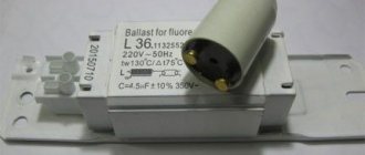
All elements can be placed in the housing of an old fluorescent lamp. It already contains everything - the case, the cartridge, the board (which can be reused). Inside, you can arrange all the elements of the power supply and the microcircuit without much difficulty. And on the outside, install an LED that you plan to power from the device. Almost any driver circuits for 220 V LEDs can be used, the main thing is to lower the voltage. This can be easily done with a simple transformer.
It is advisable to use a new circuit board. And it’s better to do without it altogether. The design is very simple, it is permissible to use wall-mounted installation. Be sure to make sure that the voltage at the rectifier output is within acceptable limits, otherwise the microcircuit will burn out. After assembly and connection, measure the current consumption. Please note that if the supply current decreases, the life of the LED element will increase.
Carefully select the driver circuit for powering the LEDs, calculate each design component - service life and reliability depend on this. With the correct selection of drivers, the characteristics of the LEDs will remain as high as possible, and the resource will not suffer. Driver circuits for high-power LEDs differ in that they contain a larger number of elements. PWM modulation is often used, but at home, as they say, “on the knee,” such devices are already difficult to assemble.
Types of schemes and their features
To create the optimal voltage for operation of a device using diodes, the driver is assembled based on a circuit with a capacitor or a step-down transformer. The first option is cheaper, the second is used to equip high-power lamps.
There is a third type - inverter circuits, which are implemented either for assembling dimmable lamps, or for devices with a large number of diodes.
Option #1 - with capacitors to reduce voltage
Let's consider an example involving a capacitor, since such circuits are common in household lamps.
Elementary circuit of an LED lamp driver. The main elements that dampen the voltage are capacitors (C2, C3), but resistor R1 also performs the same function
Capacitor C1 protects against power line interference, and C4 smoothes out ripples. At the moment the current is supplied, two resistors - R2 and R3 - limit it and at the same time protect it from a short circuit, and the VD1 element converts alternating voltage.
When the current supply stops, the capacitor is discharged using resistor R4. By the way, R2, R3 and R4 are not used by all manufacturers of LED products.
A multimeter is often used to test a capacitor.
Disadvantages of a circuit with capacitors:
- It is possible that the diodes may burn out , since the stability of the current supply is not observed. The load voltage is completely dependent on the supply voltage.
- There is no galvanic isolation , so there is a risk of electric shock. It is not recommended to touch current-carrying elements when disassembling lamps, as they are under phase.
- It is almost impossible to achieve high glow currents , because this would require an increase in capacitor capacities.
However, there are also many advantages, which is why capacitors remain popular. The advantages are ease of assembly, wide range of output voltages and low cost.
You can safely experiment with making it yourself, especially since some of the parts can be found in old receivers or televisions.
Option #2 - with a pulse driver
Unlike a linear driver with a capacitor, a pulsed one effectively protects LEDs from voltage surges and network interference.
An example of a pulse device is the popular electronic model CPC9909. Let's take a closer look at its features. The efficiency of its use reaches 98% - an indicator at which we can really talk about energy saving and savings.
The CPC9909 chip, developed by Clare, is often used for self-assembly of LED lamps, including those with increased power. The controller is housed in a compact plastic housing
The device can be powered directly from high voltage - up to 550 V, since the driver is equipped with a built-in stabilizer. Thanks to the same stabilizer, the circuit has become simpler and the cost is lower.
LED driver circuit based on the CPC9909 chip. Advantages of the circuit: ability to operate in the temperature range from -55 °C to +85 °C and powered by alternating voltage current
The microcircuit is successfully used for the development of electrical networks for emergency and backup lighting, since it is suitable for boost converter circuits.
At home, lamps powered by batteries or drivers with a power not exceeding 25 V are most often assembled based on the CPC9909.
Option #3 - with a dimmable driver
Adjusting the brightness of lighting fixtures allows you to set the desired level of lighting in the room. This is convenient for creating separate zones, reducing the brightness of light during the day, or for highlighting interior items.
With the help of a dimmer, the use of electricity becomes more rational, and the service life of the electrical appliance increases.
Sample of a retro style lamp with a dimmer. In appearance, the tabletop lighting device resembles a kerosene lamp and has a brightness control knob on the side.
There are two types of dimmable drivers, each with their own advantages. The first ones work with PWM control.
They are installed between the lamp and the power supply. Energy is supplied in the form of pulses of different durations. An example of using a driver with PWM regulation is a creeping line.
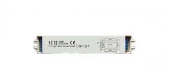
Testing a 40W dimmable driver. It is intended for office lamps, as well as devices for car parks and public buildings where energy saving mode is required
Dimmable drivers of the second type act directly on the power source and are used for devices with stabilized current.
When regulating the current, the shade of the glow may change: white diodes begin to emit slightly yellow light when the current decreases, and blue when it increases.