Accurate knowledge of the polarity of an electrical appliance is extremely important. After all, if you connect electrical equipment with incorrect polarity, it may either not work or be completely damaged. In most cases, the “plus” and “minus” of wires and contacts in such devices are indicated by letters, symbols or colors (on the case near the contacts there is a “+” and “-” marker, and the wires are black for minus and red for plus) .
But sometimes it happens that it is not possible to visually determine the poles. To do this, you can use either an ordinary polarity tester or improvised means.
Setting the measurement mode
After installing the probes, set the multimeter switch to the appropriate range.
If you are measuring the voltage at an outlet, choose a threshold value of 750 ACV, if, for example, a car battery is 20 or 200 DCV. It is always necessary to set the measurement limit higher than the expected voltage at the power supply. Otherwise, you risk burning the device.
There is a rule: voltage is measured by connecting a multimeter in parallel (while current strength is measured in series with the load). In practice, this means that in order to measure the voltage in an outlet, you simply need to insert both multimeter probes into it, each into its own socket. Where the zero is, where the phase is, it doesn’t matter.
The device shows the voltage within the limits to which it is adjusted. Thus, if you set the upper threshold to 750 V, you will see on the screen a value in the range of 210-230 V. Or less, or more, if the voltage surge is very large, but it cannot rise above 750 V. But if you set the threshold to 200 V, then when the actual voltage value is above this limit, the number 1 will appear on the screen.
Please note that there is not always exactly 220 V in a household outlet. Deviations of plus or minus 10-15 V are acceptable.
Testing a three-phase line is carried out by contacting two multimeter probes with two buses. Between them there should be 380 V, between one bus and the ground there will be 220 V (plus or minus 15).
Instead of an afterword
When buying a used car, it is useful to know how to find an electrical leak and understand its cause. Take a multimeter to inspect your car - you will save yourself from unpleasant surprises, such as a suddenly dead battery, power surges or burnt wiring.
For the same purpose, check the car's history. This can be done directly during a conversation with the seller. It’s convenient to use the Autocode service - monitor information from 13 sources at once: traffic police, RSA, EAISTO, banks, tax and other services. The verification will take 5 minutes.
Afterwards you will find out the actual mileage, number of owners, history of fines, as well as information about theft, participation in an accident, restrictions on car registration and much more. Be carefull!
Having fully studied the online report, it is still worth taking a closer look at the technical nuances of the car when purchasing. And if you are not confident in your knowledge, or it is not possible to go for an inspection, order an on-site inspection service. The specialist will conduct a diagnosis for you and make a detailed conclusion from a professional point of view.
Multimeter connectors and probes
Typically, even household multimeters have removable probes of different colors - one black, the other red, and in addition two or three connectors for connecting them on the instrument panel.
The connectors of the digital tester, as in our case, are marked as follows:
10ADC - the connector is used only for measuring direct current in the range up to 10 A. The red probe is connected to it when you need to measure current.
COM (common common) – a common connector; in various measurement modes it can also be negative or grounded. The black probe is connected to it
VΩmA – connector for basic measurements - resistance, voltage or current (except for high currents over 10A) A red probe is connected to it
The common and VΩmA connectors are most often used; the main measurements are made with them.
When you use a digital multimeter when taking measurements, do not be afraid to mix up the probes, or attach the black one to the positive terminal; if you mix up the measurement poles, the multimeter will not burn out, but will only indicate this with a “-” sign on the screen, this is how phase and zero are determined by the way for alternating current and plus and minus for direct current sources.
Where are the plus and minus located on the radio?
If the polarity of the wires of the current source is unknown, then it can be determined with a magnetoelectric voltmeter, which has the polarity of the terminals marked. The polarity of the source is judged by the direction of deflection of the voltmeter needle. In the absence of a magnetoelectric voltmeter, the polarity of the source can be determined in the following ways. The copper rods of the wires connected to the current source are lowered into a glass of acidified water, for which 2-3 cm3 of electrolyte is added to the water. If the source voltage is more than 36 V, an electric lamp of the appropriate voltage is introduced into the electric current circuit. In this case, the rods in the glass should not touch one another. When the current source is turned on, a small amount of oxygen will be released on the positive rod in the form of small bubbles, and on the negative rod hydrogen will be released in the form of large bubbles and in large quantities. Determining the polarity of the wires of a direct current source using: a - acidified water; b - potato tuber; 1 - electric lamp; 2 - drive; 3 - negative rod; 4 - positive rod 2. Copper rods of wires connected to a direct current source are inserted at some distance from one another into a cut of a potato tuber and turn on the current source. Near the positive rod, the potato starch will turn greenish-blue.
Definition of terms
So, first you need to understand these terms and understand why you are looking for this or that wire. It is necessary to remember that all electrical networks are divided into 2 categories:
- with alternating current;
- with direct current.
Current represents the movement of electrons according to a certain scenario. In the first version, electrons carry out permanent movement in a certain direction. And in the case of variable, the feature will be a constant change in the direction of movement.
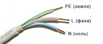
Now let's say a little about phase, zero and grounding. Electricity is supplied to the electrical network from a transformer substation, the main purpose of which is to convert high voltage to 380 V. And electricity is supplied to the house either by air or underground through an input distribution panel. Then the voltage goes to the panels located in each entrance. And already in the apartments there is one phase with zero, that is, 220 volts and a protection conductor.
The conductor that supplies electric current to the consumer will be called phase. Inside the transformer winding, they are connected to each other in a so-called star, which has a common neutral, which is grounded at the substation itself. It usually goes to the load via a separate cable. The zero, which is a common conductor, is intended to reverse the flow of current to the source of electricity. It makes it possible to equalize the phase voltage - the difference between zero and phase.
But grounding, which is popularly called earth, has no voltage. Its main task is to protect the user from the effects of electric current in the event of problems with the equipment, that is, in the event of a breakdown.
Determining polarity with a multimeter
Sometimes it happens that a new electrical device that needs to be connected does not have polarity markings or it is necessary to re-solder the wiring of a damaged device, and all the wires are the same color
In such a situation, it is important to correctly determine the poles of the wires or contacts
But if you have the necessary instruments, a logical question arises: how to determine the plus and minus of an electrical appliance with a multimeter?
To determine the polarity, the multimeter must be turned on in the mode for measuring direct voltage up to 20 V. The wire of the black probe is connected to the socket marked COM (it corresponds to the negative pole), and the red one is connected to the socket with the VΩmA marker (it is, accordingly, a plus).
After this, the probes are connected to the wires or contacts and the device, the polarity of which needs to be determined, turns on.
If the multimeter display shows a value without additional signs, then the poles are determined correctly, the contact to which the red probe is connected is positive, and the contact to which the black probe is connected will correspond to the minus.
If the multimeter shows a voltage value with a minus sign, this will mean that the probes are connected to the device incorrectly and the red probe will be a minus, and the black probe will be a plus.
If the multimeter used to measure is analog (with an arrow and a display with gradations of values), if the poles are connected correctly, the arrow will show the actual voltage value, but if the poles are reversed, then the arrow will deviate in the opposite direction relative to zero, that is, it shows a negative current value.
Charger wire polarity by color
Let us assume that you have come across some kind of constant voltage power supply or battery. It does not indicate where the plus is and where the minus is. Yes, the matter can be quickly resolved with a multimeter, but if you don’t have one at hand, and we urgently need to start the car or power some trinket? An incorrect connection can damage the power source itself, or the device or unit being powered. This is where it is important to determine the polarity of the power source using improvised means. In this article I will tell you about three simple ways. Method number 1.
Determination using a multimeter
Position of the measuring range switch on the multimeter
Any home electrician should have a multimeter in their toolbox. This is a universal tester that allows you to check the performance of electronic components, measure voltage and current, and also test circuits. An inexpensive and high-quality device with simple functionality can be purchased for 300-500 rubles. Professional electricians use more expensive devices with additional options and minimal error.
There are two types of multimeters based on the way they work - electronic and analog. Pointer or analogue is a simple device with an arrow. A digital multitester displays values in numbers. The determination method is the same for both types of devices.
Rules for working with a multimeter:
- Measurements cannot be taken at high humidity.
- Defective probes are not used.
- The measurement limit must exceed the measured value.
- When taking measurements, it is forbidden to turn the knobs or set other limits.
Currently, digital multimeters are actively used. The verification algorithm may differ.
Wiring of three wires without markings
Phase search by elimination method
You can choose the exclusion method. To find the phase, the multimeter should be assembled and the probes should be placed on the left and right - black in the COM connector, red in the voltage measurement connector. The switch should be placed in the AC voltage sector V~ or ACV. The arrow selects the voltage limit - it must exceed the network voltage. On the tester you can see values of 500, 600, 750 W depending on the model.
Then voltage measurements are taken between the stripped conductors. There may be 3 options:
- Between zero and phase there should be a voltage close to the mains 220 V.
- There can also be 220 V between the phase and the ground. If the line is protected by an RCD system, the machine may trip. If there is no RCD or there is a minimum leakage current, the displayed voltage will be within the nominal error.
- There is zero voltage between zero and ground.
Checking the contact in the socket by directly measuring the voltage
Determining phase using a multimeter
The multimeter is prepared and a control measurement of the voltage in the socket is made. This allows you to verify that there are no breaks in the line and that the device itself is working. If the numbers shown on the display are correct, the connection is correct.
The red probe needs to touch the conductor being tested. When checking the socket, the probe is placed in the socket. If you are testing the stripped end of the cable, it is recommended to connect via an alligator clip. The second probe touches the fingers. Readings are taken on the display. If the black probe is set to zero, the voltage will be zero or close to zero. When it hits a phase, the voltage will reach tens or hundreds of volts.
Touching the probe with your hand is safe in this measurement. The device was previously tested for serviceability, so a person will not be shocked by an electric shock that is life-threatening. But even despite the safety of the procedure, not everyone can cross the psychological barrier. Then you can touch the plaster, ceiling or wallpaper with the probe. They have little moisture, so the readings on the tester will be visible. They will be lower than the required value, but it is realistic to determine the phase in this way. You can also use any grounded device (heating radiator, water supply) or a metal frame without grounding as the second contact.
Search for zero and ground
Voltage measurement mode on a multimeter to determine phase
Determining the phase is not difficult. It is more difficult to distinguish zero from ground. There are different determination methods, but they are all unreliable. You can accurately determine the purpose of the core using professional instruments from the arsenal of specialists.
One way is to check with a multimeter. If the RCD is triggered, it can be judged that the tester was connected between phase and ground. Upon contact with the phase and neutral conductors, the protective device does not operate. This is due to the fact that when measuring between the phase and grounding conductors, a small leakage current is formed, which may not be enough to trigger the protective system.
The second method is calling using a multitester. The multimeter switches to the resistance measurement state. The range can be set to 200 Ohms. Be sure to turn off the voltage on the panel. After this, you should check the voltage between the conductors and the grounded object. The resistance value on the grounding conductor should be lower than on the zero one.
Correctly measure phase consumption
The house is old - in plain sight you will see a large steel plate that is clearly connected to the body. The signified is neutral. The house is powered by a three-phase voltage of 380 volts. Each apartment is often supplied with one phase. We see three clamps in addition to the ground terminal. Look where the wires go: automatic machines, switches (according to the number of apartments). A typical number of site neighbors of three simplifies the analysis task.
Now we know the method for finding the phase with a multimeter, we can safely (with caution, observing safety measures) poke with probes. Take care to set the correct range so as not to burn the device
Use measurements to confirm or refute your assumptions. There are two phases - load each equally. Examine the junction boxes, located near the ceiling (large round holes in the wall) in most older homes. Having turned off the supply to the apartment, armed with a tester, understand where and what is going. Use a radical method - cut off one plug, look where the power is lost.
The load of the two phases is uneven - correct it. It would be better to do it for automatic machines and traffic jams, which will have a positive effect on reducing the cost of switchboard equipment. To complete this topic, let’s say that the work rules provide for the implementation of such activities by at least two people. One is sure to insure and is ready to cut off the power supply, cut off the current-carrying wire, or kick the person suffering from an electric shock away from the dangerous territory.
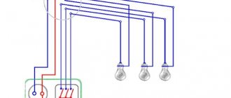
Apartment power supply diagram with two phases
What a simple multimeter can do and how to use it correctly
It requires power to make it work. A regular 1.5 volt battery is not suitable; a higher voltage is needed. In models with a large case, Krona type batteries can be used: 6F22, 1606 and others, with a voltage of 9 volts. Compact models are equipped with an A23 battery with a voltage of 12 volts. In the event of a critical discharge, the device will signal that it is impossible to carry out measurements; only the dialing mode will remain. The fact is that digital instruments use an electronic circuit for measurements, which requires a certain voltage to operate.
Pointer instruments for measuring current or voltage can operate autonomously.
But even pointer testers require power to measure the resistance of a resistor or check the health of a diode.
So, the battery is installed, the tester is ready for use. We will look at a popular digital model; dial multimeters are almost never seen in everyday life.
Before starting work (or, more correctly, purchasing a device), you need to understand why you need it. What should be the measurement limits, accuracy class, additional functions. For example, for household use there is no need to take current clamps with a measurement limit of hundreds of amperes. Functions such as measuring temperature, sound and light intensity, and humidity are certainly useful. But additional sensors increase the cost of the device, and you will use them extremely rarely.
For user convenience, many manufacturers add screen backlighting, stands, and storage cases.
This allows you to work with the device more comfortably, you just pay for each option.
In fact, the following functions are sufficient for most tasks:
- Measurement of alternating and direct voltage in the range up to 500 volts.
- Measurement of resistance and line continuity with a sound indicator.
- Current measurement up to 2 amperes.
Additional options that are almost always available even in inexpensive models:
- Checking transistors.
- Testing capacitors, sometimes with the ability to measure capacitance.
- Checking the serviceability and direction of conduction of diodes.
- Checking LEDs.
The measurement is quite simple: the control handle is set to the required mode.
The measurement limit is selected as close as possible to the expected value, but not less. For example, if you are testing the voltage on a 12 volt battery, the measurement limit is set to 15 volts (depending on the model). Then you should securely fasten the measuring cables in the sockets and connect the probes to the measuring points.
When is it necessary to determine the polarities of LED bulbs?
Small LEDs are widely used in various areas related to lighting and display:
- street lighting: advertising signs, park lighting;
- household elements of artificial light: lighting of working panels, the perimeter of the suspended ceiling, built-in furniture, etc.;
- indication of electrical appliances in on/off modes: homemade smart sockets, etc.;
- Kids toys;
- remote controls and much more.
There is information on various forums that there is no point in looking for where the LED “hides” the plus and minus. There are often opinions that a light bulb can be connected without observing polarity. There are nuances here. Even if the master is lucky and the element gives light, it will ultimately lead to the following consequences:
- The service life of an incorrectly connected light bulb, as declared by the manufacturer, will be reduced significantly. For example, with a guaranteed mode of 45,000 hours, the LED will work half as long.
- Performance (intensity, brightness of light) will decrease significantly from what it should be. In the overall circuit this will be visible to the naked eye.
Such games with polarities and the probability of operation of the diode element directly depend on the characteristics of a particular semiconductor and the breakdown voltage.
The average lifespan of LED bulbs is 10 years. With their moisture protection IP67 or more, the elements can be safely used for street lighting. In order for the LEDs to work for the stated period, it is important to observe the polarities when connecting them and determine them before carrying out repair work, and not after.
Properly inserted probes
Checking the voltage with a multimeter begins with preparing the device for operation. To do this, you need to insert the supplied probes into the sockets.
When taking DC voltage measurements or checking diodes, the red probe is “+” and the black probe is “-“.
There are three holes for probes on the front panel. Next to them there are symbols:
- COM - common contact. When carrying out any measurements, a black wire is inserted into it.
- VΩCx - connector for testing voltage, resistance and small currents. A red probe is inserted into it.
- 10A or 20A. Connector for measuring high currents.
To measure voltage, probes are inserted into holes marked “COM” and “VΩCx”. When working on an AC network, the color marking of the wires does not matter.
Important! The voltage in the socket is life-threatening, so before starting work it is necessary to check the insulation of the probes and wires
Details about the polarities of LED lamps
Such small lighting points work on the principle that current flows through them only in the forward direction. This produces optical radiation from the light bulb. If the polarity is not observed when connecting, the current will not be able to make its way through the circuit. Accordingly, the lighting device will not work.
Thus, before installing the LED, the master must know the location of its cathode and anode (“+” and “-”). This is not difficult to do if you know certain principles for visually assessing a light bulb or the operation of electrical appliances in combination with an LED element.
Rules for safe calling using a multimeter
testing a network cable with a multimeter
Working with electricity does not allow for unprofessionalism, so a certain list of rules has been developed that make it possible to make it as accurate, fast and safe as possible.
When making calls, it is most convenient to use special tips at the ends of the measuring wires, which are more commonly known as “crocodiles”. They will make the contact stable and free your hands when taking measurements. When testing, the circuit being tested must always be de-energized (even low-current batteries must be removed). If there are capacitors in the circuit, they must be discharged by short-circuiting
Otherwise, the device will simply burn out during work. Before checking the integrity of a long length of conductor when taking measurements, it is important not to touch its bare ends with your hands. This is due to the fact that the resulting readings may be incorrect.
When testing a multi-core cable, it is necessary to separate and strip all existing cores from both ends. After this, you need to check the circuit for the presence of short circuits in it: to do this, a “crocodile” is attached to each core in turn, and all the remaining ones are touched with the other measuring end in all possible combinations.
Check to see if there is a short circuit between the cable cores. If the indicator shows “1” and there is no sound signal, then everything is in order, otherwise there is a short circuit.
In this case, a sound signal will indicate the presence of a short circuit between the tested conductors
This may not be of practical importance for small cross-section multi-core cables operating in low-current networks, but when working with high voltages it is fundamentally important
We call the cable cores. There is a sound signal - everything is fine, otherwise the core is damaged.
To determine the integrity of the cores, the same operation is performed, only at one end of the cable all stripped cores are twisted together
When searching for a break, it is important to consider that the absence of a sound signal at either end will indicate a violation of the integrity of the conductor
We check the wiring in the apartment with a multimeter
Let's take as an example a modern apartment in which the wiring is done in accordance with current requirements and standards. This means that when laying the lighting lines and power outlets, they were separated, and separate wires were laid for them in each of the rooms. Each of these circuits is powered from the apartment panel through a separate circuit breaker.
If the light has gone out in one of the rooms, you should first check that the lamp is working properly. Before starting work, it is necessary to turn off the power to the room/apartment depending on the power supply. When using an opaque incandescent lamp in a lamp, the integrity of the filament is difficult to visually determine, so you will need a multimeter and its continuity function. Let's figure out step by step how to do this correctly.
First you need to check the shield for triggered circuit breakers. In the first case, they will be in the on position (then the fault may be hidden in the room switch, lamp or socket). The likelihood of damage to the wiring in such a situation is low. If the device works, you will need to check everything except the room switch, including the switchboard itself.
If the machines don't work
We ring the switch. When the switch is on, there should be a sound signal, when off, there should be silence and “1” on the indicator.
- Make sure there is voltage at the input and output of the machine. If it is, you can proceed to further verification.
- Prepare the device for operation and check its serviceability by short-circuiting the measuring leads.
- Unscrew the lamp from the socket.
- Touch one of the measuring probes to the base (the metal part of the lamp with threads), and the second to the central contact of the lamp (the insulated center of the end part of the base).
- A sound signal and instrument readings that are different from 0 or 1 mean that the lamp is working. If it is faulty, you need to replace it, which will solve the problem.
- We check the cartridge for serviceability. To do this, you need to disassemble the lamp, make sure that the connected wires and contacts are intact. If everything is in order, then the cause of the failure is not in the cartridge. If malfunctions are detected, they must be eliminated. The lamp cannot be screwed in yet.
- We check the serviceability of the room switch. To do this, remove the plastic cover, unscrew the screws and take it out of the mounting box. We inspect the equipment for the appearance of carbon deposits and check the tightness of the fasteners. If everything is in order, you need to install the measuring ends of the tester on the contacts of the switch. The appearance of a sound signal when dialing in the on position will indicate that the equipment is working properly. The wires do not need to be disconnected.
During such a check, as a rule, a malfunction is identified, which becomes the cause of all the troubles. Eliminating it allows you to quickly solve the problem.
If the machine worked
To ensure electrical safety during work, in this case the voltage is turned off using a general apartment circuit breaker. Next, the serviceability of the socket and the wires connected to the lamp is determined according to the algorithm described above. If there are no faults, you need to check the wiring itself using a multimeter and the continuity function. Such malfunctions happen quite rarely, but they still happen, for example, when installing suspended ceilings or decorative interior elements.
The wiring in this case is performed as follows.
- Using a screwdriver, disconnect the connected conductor (if installed correctly, it is located at the bottom) and move it to the side. The “zero” of this group is, as a rule, located at the zero clamp under the machines.
- Unscrew the incandescent lamp from the socket. Using a ready-to-use tester, we check the line by connecting one of the measuring probes to “zero” and the other to the disconnected conductor. If the device beeps, it means the wiring is shorted.
- In this case, in the room under the ceiling above the switch, we find and open the junction box. We disconnect the wires.
- We check all groups of wires for short circuits. To determine the section of the circuit in which there is a short circuit, we again check the circuits on the apartment panel with a multimeter. If the signal sounds, it means that it is the wire laid from the switchboard to the box in the room that needs to be repaired. Otherwise, the search will need to be continued until a result is obtained.
Determining the purpose of conductors
When working with electrical wiring, be sure to double-check the assignment of the outlet conductors. There is no guarantee that the electrician or the previous owner of the premises did not mix up the wires. Therefore, if the tester shows a voltage of 220 V relative to a terminal that appears to be grounding, this does not mean that it is such.
This means that one of the contacts is a phase, and the second is a zero or ground. If the tester shows 0, then there is a neutral and ground conductor. It is impossible to understand exactly what is what.
If you are not 100% sure of the purpose of the grounding terminal, the sockets operate differently. First you need to exclude the presence of two phases. Check the voltage between all contacts. If the device does not show 380 V anywhere, but only 220, it means that one phase conductor is connected to the socket. Now you need to start looking for grounding.
First you need to disconnect the grounding conductor in the floor panel. It is connected through a bolted connection to a special bus welded to the body of the electrical panel.
After this, the voltage between the socket connectors is measured.
If the device shows 220 V, then the socket contacts are the phase and neutral wires, and the ground terminal really is. Now knowing exactly where the ground is, you can determine the remaining connectors, but first you need to reconnect the “ground” to the ground bus.
We measure the voltage relative to the ground terminal. One socket shows 220 V - this is a phase, the second - 0, then this is a zero contact.
If the multimeter shows 0, then the ground has been connected to one of the socket contacts, and the second is neutral or phase. Now we take measurements between the socket and ground contact of the socket. If there is no voltage, then this socket is the real ground.
The readings at 220 V speak for themselves.
Does the location of the phase and zero in the socket matter?
Sockets used in the CIS countries allow plugs to be turned on in two ways, and the plugs themselves are arranged symmetrically, so when turned on, the phase in the socket can be connected to any of the pins of the plug.
For the operation of most electrical appliances, the polarity of the plug in the outlet does not matter. In turn, when turning on the plug, ordinary consumers do not pay attention to its position. The exception is plugs, in which the cable is located at an angle of 90° to the pins. These devices are turned on in a way that is more convenient for them to use.
There is an opinion that, according to the PUE and other regulatory documents, the phase should be connected to the right terminal of the socket, but this is not so. Not a single document or instruction indicates the correct position of the phase in the socket and where to connect it is determined by the installer during installation.
Given the possibility of turning on the device in any way, circuit breakers in electrical appliances disconnect both supply wires.
Determining phase and zero with a multimeter or screwdriver
Multimeter
The device is a combined electrical measuring device capable of performing several functions. The minimum configuration includes a voltmeter, ohmmeter and ammeter. Some modifications are made in the form of current clamps. Both analog and electronic meters are available.
To begin the measurement process, you must switch to AC voltage measurement mode. Measurement is carried out using one of several methods:
- We clamp one of the existing probes with two fingers. We direct the second probe to the contact, which is located in the switch or socket. If the data on the monitor is insignificant (does not exceed 10 volts), we are talking about zero. If you touch another contact, the indicator will be higher - this is a phase.
- If there are concerns about touching the dipstick, there is another way. We direct one of the rods into the socket. With the second rod we touch directly to the wall next to the outlet. The result will be approximately the same as in the case described above.
- There is a third way to measure using a multimeter. We touch the probe to a grounded surface (for example, the equipment body). We touch the surface to be measured with the second probe. If the wire is a phase, the multitester will detect a voltage of 220 volts.
Indicator screwdriver
The indicator is a simple way to determine the phase, accessible even to a person who is doing this for the first time. The test screwdriver looks like a standard one. The difference lies in the internal structure of the indicator screwdriver. The screwdriver handle is made of special transparent plastic. There is a diode inside. The upper part is made of metal.
Note! The indicator screwdriver must not be used for purposes other than its intended purpose. It is not intended for loosening or tightening screws.
Improper use of the test screwdriver will cause its failure.
To find phase and zero using a screwdriver, you need to perform the following sequence of operations:
- Use the end of a screwdriver to touch the contact.
- Press the metal button at the top of the screwdriver with your finger.
- If the LED lights up, we are talking about a phase. If it doesn't react, it's zero.
Note! An indicator lamp rated for 220-380 volts will glow at voltages greater than 50 volts. When working with an indicator screwdriver, it is recommended to adhere to the following safety precautions:
When working with an indicator screwdriver, it is recommended to adhere to the following safety precautions:
- Do not touch the bottom end of the screwdriver while taking measurements.
- Keep the screwdriver clean, otherwise there is a high risk of insulation damage.
- If you need to determine the absence of voltage, first check the functionality of the device, which is definitely under voltage.
Advice! In a DC network, the polarity of the contacts is determined in a very simple way. To do this, simply immerse the wires in a container of water. Bubbles will begin to form near one of the wires - this is a minus. The second wire is positive.
An indicator screwdriver should not be confused with a dialing device. The dialing screwdriver is equipped with batteries. When working with such a device, you do not need to press the button to determine zero and phase, since the screwdriver will light up in any possible situation.
How to easily determine the polarity of the power supply wire
Forgot your password? Author subaru, Tell me how to do this? I connected it in different ways, I can’t tell by ear. Maybe there is some kind of mp3 file with a low-frequency recording, with which you can determine which way the speaker cone goes, just like with a battery?
Leave a comment 6. Connect the test leads to the terminals of the charger and turn it on. To check the polarity of the speakers, briefly touch the speaker terminals with wires from a 3-volt battery. When the speaker cone moves outward, the polarity of the speaker terminals matches the polarity of the battery.
Forgot your password? Forum General forums Music in the car Plus and Minus wires. Showing 1 to 16 of Topic Options Subscribe to this topic….
View full version: How to determine the polarity when connecting a thermocouple with a temperature compensation wire. Sometimes I get confused when connecting the thermocouple to the TRM. Within a range of up to 30 degrees, the TRM with one or another connection of the polarity to the thermocouple with a temperature compensation wire shows either 25 or 30 degrees. Which is the correct largest or smallest value? Sometimes there is no time to run for a thermometer. If it were in the minus, there would be no questions, but here the degrees jump, well, it seems that it happened even more.
Which outlet? There is a phase and a zero. You can determine it using an indicator screwdriver: where the phase is, it will light up, where 0 is not. If we are talking about a socket where the voltage is constant, for example a telephone socket, you can determine the polarity using a multimeter tester, or an LED with a resistor, the resistor must be designed for the appropriate voltage.
What is the voltage at the outlet?
More precisely, what should it be? In Russia, the most common indicators in a centralized network are 220 and 380 volts, with a frequency of 50 Hz. The permissible deviation, in one direction or another, is considered to be 10%. That is, an error of up to 198 or 242 volts will be normal.
These fluctuations can depend both on the heavy load on the network, on high-power electrical appliances (heaters, boilers, welding machines), and on the servicing power plant. But whatever the reason, it is recommended to sometimes monitor the voltage in the outlet at home in order to avoid possible unpleasant consequences.