All known types of conductors have certain properties, including electrical resistance. This quality has found its application in resistors, which are circuit elements with a precisely set resistance. They allow you to adjust current and voltage with high precision in circuits. All such resistances have their own individual qualities. For example, the power for parallel and series connection of resistors will be different. Therefore, in practice, various calculation methods are often used, thanks to which it is possible to obtain accurate results.
Power in series connection
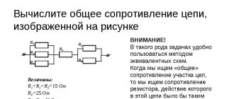
When resistors are connected in series, electric current passes through each resistance in turn. The current value at any point in the circuit will be the same. This fact is determined using Ohm's law. If you add up all the resistances shown in the diagram, you get the following result: R = 200+100+51+39 = 390 Ohms.
Considering the voltage in the circuit is 100 V, according to Ohm’s law, the current will be I = U/R = 100/390 = 0.256 A. Based on the data obtained, the power of the resistors in a series connection can be calculated using the following formula: P = I2 x R = 0.2562 x 390 = 25.55 W.
In the same way, you can calculate the power of each individual resistor:
- P1 = I2 x R1 = 0.2562 x 200 = 13.11 W;
- P2 = I2 x R2 = 0.2562 x 100 = 6.55 W;
- P3 = I2 x R3 = 0.2562 x 51 = 3.34 W;
- P4 = I2 x R4 = 0.2562 x 39 = 2.55 W.
If we add up the received power, then the total P will be: P = 13.11 + 6.55 + 3.34 + 2.55 = 25.55 W.
Three-phase connection of heaters
Delta connection
The rated voltage of each heating element is identical to the voltage between phases in a delta connection.
Star connection
The rated voltage of heating elements is equal to the phase-to-phase voltage of three-phase wiring divided by the root of 3 or 1.732
Connection example: 3 1000 W 230 V heating elements connected to a 400 V three-phase network generate 3000 W. 3 1000W 400V heating elements connected to a 400V three phase power supply generate 1000W.
Read more about three-phase connection of heating elements in our article - triangle or star for connecting heaters
Resistance dependence
The value of electrical conductivity depends on several factors that must be taken into account when calculating, manufacturing resistive load elements (resistors), repairing and designing devices. These factors include the following:
- Ambient and material temperature.
- Electrical quantities.
- Geometric properties of matter.
- The type of material from which the conductor (semiconductor) is made.
Electrical quantities include potential difference (voltage), electromotive force (EMF) and current. The geometry of a conductor is its length and cross-sectional area.
Electrical quantities
The dependence of electrical conductivity on electrical parameters is determined by Ohm's law. There are two formulations: one for a section, and the other for a complete chain.
In the first case, the ratio is determined based on the values of current (I) and voltage (U) by a simple formula: I = U / R. From the ratio one can see that the current is directly proportional to the voltage value, as well as inversely proportional to the resistance. You can express R: R = U / I.
To calculate the electrical conductivity of the entire section, you should use the relationship between the emf (e), current strength (i), and also the internal resistance of the power source (Rin): i = e / (R+Rin). In this case, the value of R is calculated using the formula: R = (e / i) - Rin. However, when performing calculations, it is also necessary to take into account geometric parameters and the type of conductor, since they can significantly affect the calculations.
Type and geometric parameters
The property of a substance to conduct electricity is determined by the structure of the crystal lattice, as well as the number of free carriers. Based on this, the type of substance is the key factor that determines the amount of electrical conductivity.
In science, the coefficient that determines the type of substance is denoted by the letter “p” and is called resistivity. Its value for various materials (at a temperature of +20 degrees Celsius) can be found in special tables.
Sometimes, for convenience of calculations, the inverse quantity is used, which is called specific conductivity (σ). It is related to resistivity by the following relationship: p = 1 / σ. Cross-sectional area (S) affects electrical resistance. From a physical point of view, the dependence can be understood as follows: with a small cross section, more frequent interactions of electric current particles with the nodes of the crystal lattice occur. The cross section can be calculated using a special algorithm:
- Measuring the geometric parameters of the conductor (diameter or side length) using a caliper.
- Visually determine the shape of the material.
- Calculate the cross-sectional area using the formula found in a reference book or on the Internet.
In the case when the conductor has a complex structure, it is necessary to calculate the value S of one element, and then multiply the result by the number of elements included in its composition. For example, if the wire is multi-core, then S should be calculated for one wire. After this, you need to multiply the resulting value S by the number of cores. The dependence of R on the above values can be written as a ratio: R = p * L / S. The letter “L” is the length of the conductor. However, to obtain accurate calculations, it is necessary to take into account the temperature indicators of the external environment and the conductor.
Temperature indicators
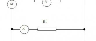
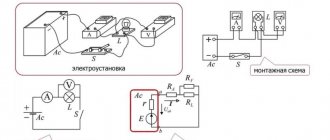
There is evidence that the resistivity of a material depends on temperature, based on physical experiment. To conduct the experiment, you need to assemble an electrical circuit consisting of the following elements: a power source, a nichrome spiral, connecting wires of an ammeter and a voltmeter. Instruments are needed to measure current and voltage values, respectively. When electricity flows, the nichrome spring heats up. As it heats up, the ammeter readings decrease. In this case, a significant voltage drop occurs in the circuit section, as evidenced by the voltmeter readings.
In radio engineering, a decrease in voltage is called a sag or drop. The formula for the dependence of p on temperature is as follows: p = p0 * [1 + a * (t - 20)]. The value p0 is the resistivity of the material taken from the table, and the letter “t” is the temperature of the conductor.
The temperature coefficient “a” takes on the following values: for metals - a>0, and for electrolytic solutions - a Combining resistive radio components
To obtain the required resistance value, two types of resistor connections are used: parallel and series. If you connect them in parallel, then you need to connect the two terminals of one resistor to the two terminals of the other. If the connection is in series, then one terminal of the resistor is connected to one terminal of the other resistor. Connections are used to obtain the required resistance ratings, as well as to increase the power dissipation of the current flowing through the circuit.
Each of the compounds has certain characteristics. In addition, several resistors can be combined in series or parallel. Connections can also be mixed, i.e., both types of combining radio components can be used.
Parallel connection
When connected in parallel, the voltage across all resistors is the same, and the current is inversely proportional to their total resistance. On the Internet, web developers have created an online calculator to calculate the total resistance of a parallel connection of resistors.
Read also: How to make a musket from wood
The total resistance in a parallel connection is calculated using the formula: 1 / Rtot = (1 / R1) + (1 / R2) + …+ (1 / Rn). If you perform mathematical transformations and bring them to a common denominator, you will get a convenient parallel connection formula for calculating Rtotal. It has the following form: Rtot = (R1 * R2 * … * Rn) / (R1 + R2 + … + Rn). If it is necessary to calculate the value of Rtot for only two radio components, then the parallel resistance formula has the following form: Rtot = (R1 * R2) / (R1 + R2).
When repairing or designing a device circuit, the task arises of combining several resistive elements to obtain a specific resistance value. For example, the value of Rtotal for a certain chain of elements is equal to 8 Ohms, which was obtained during calculations. The radio amateur is faced with the task of choosing which values to select to obtain the desired value (in the standard series of resistors there is no radio component with a rating of 8 ohms, but only 7.5 and 8.2). In this case, you need to find the resistance when connecting resistive elements in parallel. You can calculate the value of Rtot for two elements as follows:
- A 16 ohm resistor value is fine.
- Substitute into the formula: R = (16 * 16) / (16 + 16) = 256 / 32 = 8 (Ohm).
In some cases, you may need to spend more time selecting the required denominations. You can use not only two, but also three elements. The current strength is calculated using Kirchhoff's first law. The formulation of the law is as follows: the total value of the current entering and flowing through the circuit is equal to its output value. The current value for a circuit consisting of two resistors (parallel connection) is calculated using the following algorithm:
- Current flowing through R1 and R2: I1 = U / R1 and I2 = U / R2 respectively.
- Total current - addition of currents on resistors: Itotal = I1 + I2.
For example, if the circuit consists of 2 resistors connected in parallel, with values of 16 and 7.5 ohms. They are powered from a 12 V power supply. The current value of the first resistor is calculated as follows: I1 = 12 / 16 = 0.75 (A). The current on the second resistor will be equal to: I2 = 12 / 7.5 = 1.6 (A). The total current is determined by Kirchhoff's law: I = I1 + I2 = 1.6 + 0.75 = 2.35 (A).
Serial connection
Series connection of resistors is also used in radio engineering. The methods for finding total resistance, voltage and current are different from parallel connections. The basic connection rules are as follows:
- The current does not change along the circuit section.
- The total voltage is equal to the sum of the voltage drops across each resistor.
- Rtot = R1 + R2 + … + Rn.
An example of the problem is as follows: a chain consisting of 2 resistors (16 and 7.5 Ohms) is powered from a source with a voltage of 12 V and a current of 0.5 A. It is necessary to calculate the electrical parameters for each element. The calculation procedure is as follows:
- I = I1 = I2 = 0.5 (A).
- Rtotal = R1 + R2 = 16 + 7.5 = 23.5 (Ohm).
- Voltage drops: U1 = I * R1 = 0.5 * 16 = 8 (V) and U2 = I * R2 = 0.5 * 7.5 = 3.75 (V).
The voltages are not always equal (12 V is not equal to 8 + 3.75 = 11.75 V), since this calculation does not take into account the resistance of the connecting wires. If the diagram is complex and there are two types of connections in it, then you need to perform calculations by section. First of all, calculate for a parallel connection, and then for a serial one.
Thus, parallel and series connections of resistors are used to obtain more accurate resistance values, as well as in the absence of the required rating of the radio component when designing or repairing devices.
In electrical circuits, elements can be connected in various ways, including serial and parallel connections.
Serial connection
With this connection, the conductors are connected to each other in series, that is, the beginning of one conductor will be connected to the end of the other. The main feature of this connection is that all conductors belong to one wire, there are no branches. The same electric current will flow through each of the conductors. But the total voltage on the conductors will be equal to the combined voltages on each of them.
Consider a number of resistors connected in series. Since there are no branches, the amount of charge passing through one conductor will be equal to the amount of charge passing through the other conductor. The current strength on all conductors will be the same. This is the main feature of this connection.
This connection can be viewed differently. All resistors can be replaced with one equivalent resistor.
The current across the equivalent resistor will be the same as the total current flowing through all resistors. The equivalent total voltage will be the sum of the voltages across each resistor. This is the potential difference across the resistor.
If you use these rules and Ohm's law, which applies to each resistor, you can prove that the resistance of the equivalent common resistor will be equal to the sum of the resistances. The consequence of the first two rules will be the third rule.
Application
A serial connection is used when you need to purposefully turn on or off a device; the switch is connected to it in a series circuit. For example, an electric bell will only ring when it is connected in series with a source and a button.
According to the first rule, if there is no electric current on at least one of the conductors, then there will be no electric current on the other conductors. And vice versa, if there is current on at least one conductor, then it will be on all other conductors. A pocket flashlight also works, which has a button, a battery and a light bulb. All these elements must be connected in series, since the flashlight needs to shine when the button is pressed.
Sometimes a serial connection does not achieve the desired goals. For example, in an apartment where there are many chandeliers, light bulbs and other devices, you should not connect all the lamps and devices in series, since you never need to turn on the lights in each of the rooms of the apartment at the same time. For this purpose, serial and parallel connections are considered separately, and a parallel type of circuit is used to connect lighting fixtures in the apartment.
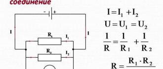
Parallel connection
In this type of circuit, all conductors are connected in parallel to each other. All the beginnings of the conductors are connected to one point, and all the ends are also connected together. Let's consider a number of homogeneous conductors (resistors) connected in a parallel circuit.
Read also: Calculation of pulley rotation speed calculator
This type of connection is branched. Each branch contains one resistor. The electric current, having reached the branching point, is divided into each resistor and will be equal to the sum of the currents at all resistances. The voltage across all elements connected in parallel is the same.
All resistors can be replaced with one equivalent resistor. If you use Ohm's law, you can get an expression for resistance. If, with a series connection, the resistances were added, then with a parallel connection, the inverse values of them will be added, as written in the formula above.
Application
If we consider connections in domestic conditions, then in an apartment lighting lamps and chandeliers should be connected in parallel. If we connect them in series, then when one light bulb turns on, we turn on all the others.
With a parallel connection, we can, by adding the corresponding switch to each of the branches, turn on the corresponding light bulb as desired. In this case, turning on one lamp in this way does not affect the other lamps.
All electrical household devices in the apartment are connected in parallel to a network with a voltage of 220 V, and connected to the distribution panel. In other words, parallel connection is used when it is necessary to connect electrical devices independently of each other. Serial and parallel connections have their own characteristics. There are also mixed compounds.
Current work
The series and parallel connections discussed earlier were valid for voltage, resistance and current values being the fundamental ones. The work of the current is determined by the formula:
A = I x U x t , where A is the work of the current, t is the flow time through the conductor.
To determine operation with a series connection circuit, it is necessary to replace the voltage in the original expression. We get:
A=I x (U1 + U2) x t
We open the brackets and find that in the entire diagram, the work is determined by the amount at each load.
We also consider a parallel connection circuit. We just change not the voltage, but the current. The result is:
A = A1+A2
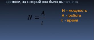
Current power
When considering the formula for the power of a circuit section, it is again necessary to use the formula:
P=U x I
After similar reasoning, the result is that series and parallel connections can be determined by the following power formula:
P=P1 + P2
In other words, for any circuit, the total power is equal to the sum of all powers in the circuit. This can explain that it is not recommended to turn on several powerful electrical devices in an apartment at once, since the wiring may not withstand such power.
The influence of the connection diagram on the New Year's garland
After one lamp in a garland burns out, you can determine the type of connection diagram. If the circuit is sequential, then not a single light bulb will light up, since a burnt out light bulb breaks the common circuit. To find out which light bulb has burned out, you need to check everything. Next, replace the faulty lamp, the garland will function.
When using a parallel connection circuit, the garland will continue to work even if one or more lamps have burned out, since the circuit is not completely broken, but only one small parallel section. To restore such a garland, it is enough to see which lamps are not lit and replace them.
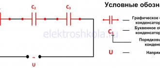
Series and parallel connection for capacitors
With a series circuit, the following picture arises: charges from the positive pole of the power source go only to the outer plates of the outer capacitors. Capacitors located between them transfer charge through the circuit. This explains the appearance of equal charges with different signs on all plates. Based on this, the charge of any capacitor connected in a series circuit can be expressed by the following formula:
qtotal= q1 = q2 = q3
To determine the voltage on any capacitor, you need the formula:
U=q/С
Where C is capacity. The total voltage is expressed by the same law that is suitable for resistances. Therefore, we obtain the capacity formula:
С= q/(U1 + U2 + U3)
To make this formula simpler, you can reverse the fractions and replace the ratio of the potential difference to the charge on the capacitor. As a result we get:
1/C= 1/C1 + 1/C2 + 1/C3
The parallel connection of capacitors is calculated a little differently.
The total charge is calculated as the sum of all charges accumulated on the plates of all capacitors. And the voltage value is also calculated according to general laws. In this regard, the formula for the total capacitance in a parallel connection circuit looks like this:
С= (q1 + q2 + q3)/U
This value is calculated as the sum of each device in the circuit:
C=C1 + C2 + C3
Heating elements for water are standard and can be ordered according to the drawing and technical specifications. task
You can order heating elements for water, heating elements for oil, heating elements for air and other media, find out about availability and delivery times by calling or write a request by email:
mob.
t.f. (499)948-03-51
tel. Email: