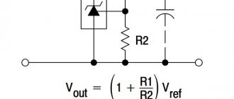
And now about the modifications that are necessary to bring this “indicator” to fruition. If the resistance of the ammeter is low, the power loss in it is also low.
Black with a minus. But the car voltmeter fig. When connecting the device to a DC network, the polarity of the connection is shown on the display. The potential at the phase output changes from positive to negative with a frequency of 50 Hz, so the current under load will change its direction 50 times per second. Voltmeter ammeter with aliexpress - connection, calibration and modification Measuring current transformers Measuring current transformers are used to connect ammeters to alternating current circuits. Measuring current transformers Measuring current transformers are used to connect ammeters to alternating current circuits. The potential at the phase output changes from positive to negative with a frequency of 50 Hz, so the current under load will change its direction 50 times per second.
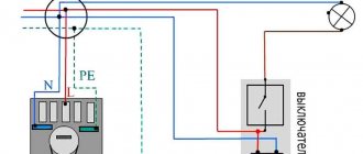
Also, in addition to the standard circuit, we will describe how to connect a voltammeter to a charger. How to connect a voltammeter to a charger - a selection of circuits. We have selected the 4 most common voltammeters that craftsmen use in their devices. The voltage from the vehicle's on-board network through the divider R1-R2-R3 is supplied to the input of the D1 microcircuit. DC voltage measurement To measure DC voltage between two points of a circuit, parallel to the circuit, between these two points, connect a voltage class=»aligncenter» width=»960″ height=»720″[/img] DC voltage Methods for measuring DC voltage depend on its values: up to 1 millivolt - digital and analog devices with a built-in amplifier; up to volts use conventional devices of various systems; above 1 kV, measurements are made with electrostatic devices designed for operation in high-voltage networks or conventional ones connected through a divider.
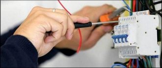
VOLTMETER-AMMETER TEST, CALIBRATION, CONNECTION DIAGRAM. ALIEXPRESS
Connection circuits for an ammeter and a voltmeter.
Figures 4.3 and 4.4 show circuits for connecting a voltmeter and an ammeter through voltage (VT) and current (CT) measuring transformers, respectively.
Rice. 4.3. Voltage transformer.
Voltmeter connection diagram:
?/,, U2_
primary and secondary voltages of VT;
Wv W2
- primary and secondary windings of the voltage transformer;
V
- voltmeter
Rice. 4.4.
Measuring current transformer. Ammeter connection diagram:
/р/2 - primary and secondary currents of the CT; Wv W2
— primary and secondary windings of the CT;
A
- ammeter
Ammeters, milliammeters and microammeters of various systems are used to measure current in electrical circuits. They are connected in series to the circuit, and all the current flowing in the circuit passes through them (Fig. 4.4)
It is important that during various electrical measurements the ammeter influences the electrical mode of the circuit in which it is connected as little as possible. Therefore, the ammeter must have a low intrinsic resistance compared to the circuit resistance
It is impossible to connect an ammeter to a current source (power supply) without a load, since in this case a large current will pass through its winding and it may burn out. For the same reason, the ammeter cannot be connected in parallel with the load.
Each ammeter is designed for a certain maximum current, above which the ammeter may burn out. If you need to use an ammeter to measure a current that exceeds the permissible current for a given ammeter, then a shunt is connected in parallel to the ammeter, i.e. expand the ammeter's measurement limits.
A shunt represents a relatively small but precisely known resistance. The circuit diagram for connecting an ammeter with a shunt is shown in Fig. 4.5, a.
The shunt must have four terminals to eliminate the influence of transient contact resistances on the shunt resistance. Shunts are made from manganin, an alloy whose temperature coefficient of resistance is practically zero.
Rice. 4.5.
Ammeter connection diagram:
A -
with shunt;
6
- through a current transformer;
for circuit a: 1 -
shunt;
2
- load;
for scheme b: 1
— measuring current transformer;
2
- load
Rice. 4.6. Connection diagram of three ammeters through two current transformers:
L j and L2 - the beginning and end of the primary winding of the current transformer; And, and I2 - the beginning and end of the secondary winding of the current transformer; L
- ammeters;
iA, iB, ic -
currents in phases
Rice. 4.7.
Voltmeter connection diagram:
R
- circuit resistance;
V—
voltmeter
Figure 4.6 shows a diagram of connecting three ammeters through two current transformers.
As can be seen from the diagram, a current iA passes through the first ammeter ,
through the second -
iB,
therefore, the current in the third ammeter, equal to the sum of two linear currents
iA
and
iB,
is equal to the third linear current:
ic = iA
+
iB.
Voltmeters are used to measure the voltage on a section of a circuit. The voltmeter is connected in parallel to those points of the circuit (M, N),
the voltage between which must be measured (Fig. 4.7).
The voltmeter should not change the voltage in the measured section of the circuit; for this reason, the current passing through the voltmeter must be much less than the current in the measured section.
In order for the voltmeter not to introduce noticeable distortions into the measured voltage, its resistance must be large compared to the resistance of the section of the circuit on which the voltage is measured. Any voltmeter is designed for a certain maximum voltage, but by connecting it in series with an additional resistance voltmeter /?ext you can measure higher voltages (Fig. 4.8, b).
Rice. 4.8.
Schemes for connecting an ammeter and voltmeter to an electrical circuit:
A
— without expanding the measurement limits;
b -
with expansion of measurement limits;
Yash
— shunt resistance; /?ext - additional resistance
Figure 4.9 shows a diagram of connecting a wattmeter to a single-phase high-voltage circuit through current and voltage measuring transformers.
Rice. 4.9.
Scheme for connecting a wattmeter to a single-phase high-voltage circuit through current and voltage measuring transformers:
V—
voltmeter;
A - ammeter; W—
wattmeter
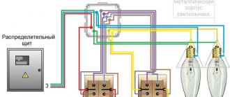
Figure 4.10 shows a diagram for connecting ammeters and voltmeters to a three-phase circuit. As can be seen from the diagram, ammeters are connected through measuring CTs, and voltmeters are connected through measuring VTs. Such circuits for connecting measuring instruments are typical for high-voltage networks with voltages of 6 (10) kV and higher.
Rice. 4.10.
Connecting ammeters and voltmeters to a three-phase circuit using current and voltage measuring transformers
The ammeter is connected to the electrical circuit in series
Conversion of Torque units. Torque units, torque units, torque units, torque units. Table
That is, we have a wire through which electric current flows from the source of this current to the consumer, which can be an electrical device.
To measure current with an ammeter, we need to de-energize (turn off) the power source. Then you need to break the chain - literally and figuratively. Roughly speaking, cut the wire.
Now we have two wires. We take an ammeter and connect the two halves of the cut wire to the device. It is necessary to take into account the fact that the current flowing in the circuit must be less than the maximum measured current of the device. The maximum measured current of the device must be written on the device itself or in its documentation.
The maximum current in a circuit can be calculated by knowing the voltage, load and wire cross-section. The wires must be insulated (covered with insulation) and stripped at the ends.
After the wires are connected and securely fixed in the ammeter, you can turn on the power and the device will show the amount of current in the circuit, which will pass through the ammeter.
But no one does this, because cut wires do no good.
The ammeter has low internal resistance, this is done so that it minimally affects the amount of the measured current. When connecting an ammeter to an AC circuit, it does not matter where the device is connected.
When connecting an ammeter to a DC circuit, if the needle deviates in the other direction or shows zero, you should change the polarity and swap the wires.
Connecting an ammeter via a shunt
If the current in the circuit turns out to be greater than the current of the device, then a shunt can be calculated and used to measure the current of a larger value. In this case, the chain will split into two branches. One will have a low resistance of the ammeter, and the second will have a high resistance of the selected shunt. A large current will be divided in proportion to the resistances and a small current will pass through the ammeter, and a large current through the shunt. (More details about this phenomenon).
Measuring current with an ammeter through a current transformer or clamp
There are times when you need to measure the current in a cable, on a bus...an isolated bus. A bus is a copper strip of a certain cross-section through which current flows, not a car wheel...
Cutting a cable or bus can be expensive and pointless. In this case, you can use a clamp meter or a current transformer.
The current transformer has two windings - higher and lower, which are not interconnected. The current arrives at the higher one, then an EMF is created (in more detail about the principle of operation of the CT) and a current flows in the secondary winding, proportional to the number of turns of the windings. So, if there is a need to measure the current, then a “donut” is hung on the cable, also known as a TT. And an ammeter is connected to the current transformer. The main thing here is to be properly instructed and not to mess things up. It turns out that we take the current with an ammeter from the secondary winding, converted to a smaller side and safe for measurement and an ammeter.
The same principle is used in clamp meters, only the ammeter and CT are located in the same housing. And plus, the primary winding of the pliers opens with one press of a button on the housing and then closes.
These two described solutions are much more convenient than cutting the wire and connecting it to the ammeter. The main thing is to monitor the ranges of currents measured by instruments and flowing in electrical circuits.
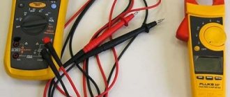
Multimeters allow you to measure direct current up to 10 Amps. But they are often fired because they connect the ends to the device incorrectly and do not take into account the amount of current in the wires... But these are mostly young people. Often, to “fix” such a malfunction, you simply need to replace the fuse in the device.
Well, in the end I would like to repeat once again the main idea of the entire story:
Latest articles
Most popular
Current measurement. Ammeter.
And we'll start by measuring the current. The device used for these purposes is called an ammeter and it is connected in series to the circuit. Let's look at a small example:
As you can see, here the power supply is connected directly to the resistor. In addition, the circuit contains an ammeter connected in series with a resistor. According to Ohm's law, the current strength in this circuit should be equal to:
I = \frac{U}{R} = \frac{12}{100} = 0.12
We obtained a value equal to 0.12 A, which exactly coincides with the practical result shown by the ammeter in the circuit
An important parameter of this device is its internal resistance r_A
Why is this so important? See for yourself - in the absence of an ammeter, the current is determined according to Ohm's law, as we calculated a little higher. But if there is an ammeter in the circuit, the current will change because the resistance will change, and we will get the following value:
I = \frac{U}{R_1+r_A}
If the ammeter were absolutely ideal and its resistance was zero, then it would not have any effect on the operation of the electrical circuit whose parameters need to be measured, but in practice this is not entirely true, and the resistance of the device is not equal to 0. Of course, the resistance of the ammeter is sufficient is small (since manufacturers strive to reduce it as much as possible), so in many examples and tasks it is neglected, but do not forget that it still exists and is non-zero.
When talking about measuring current, it is impossible not to mention a method that allows you to expand the limits within which the ammeter can operate. This method involves connecting a shunt (resistor) having a certain resistance in parallel to the ammeter:
R = \frac{r_A}{n\medspace-\medspace 1}
In this formula, n is the shunt coefficient - a number that shows how many times the limits within which the ammeter can make its measurements will be increased. Perhaps all this may not seem entirely clear and logical, so now we will look at a practical example that will help you understand everything.
Let the maximum value that the ammeter can measure be 1 A. And the circuit in which we need to determine the current strength has the following form:
The difference from the previous circuit is that the voltage of the power source in this circuit is 100 times greater, and accordingly, the current in the circuit will become greater and will be equal to 12 A. Due to the limitation on the maximum value of the measured current, we will not be able to directly use our ammeter . So, for such tasks you need to use an additional shunt:
In this problem, we need to measure the current I. We assume that its value will exceed the maximum permissible value for the ammeter used, so we add another element to the circuit that will act as a shunt. Let us want to increase the measurement limits of the ammeter by 25 times, this means that the device will show a value that is 25 times less than the value of the measured current. All we have to do is multiply the readings of the device by the number we know and we will get the value we need. To implement our idea, we must place a shunt parallel to the ammeter, and its resistance must be equal to the value that we determine using the formula:
R = \frac{r_A}{n\medspace-\medspace 1}
In this case, n = 25, but we will carry out all the calculations in a general form to show that the values can be absolutely any, the shunting principle will work the same.
So, since the voltages across the shunt and the ammeter are equal, we can write the first equation:
I_A\medspace r_A = I_R\medspace R
Let us express the shunt current in terms of the ammeter current:
I_R = I_A\medspace \frac{r_A}{R}
The measured current is:
I = I_R + I_A
Let us substitute the previous expression for the shunt current into this equation:
I = I_A + I_A\medspace \frac{r_A}{R}
But we also know the resistance of the shunt (R = \frac{r_A}{n\medspace-\medspace 1}). As a result we get:
I = I_A\medspace (1 + \frac{r_A\medspace (n\medspace-\medspace 1)}{r_A}\enspace) = I_A\medspace n
So we got what we wanted. The value that the ammeter will show in this circuit will be n times less than the current strength, the value of which we need to measure
Everything is clear with measuring the current in the circuit, let's move on to the next question, namely determining the voltage.
How is an ammeter connected to a circuit?
Now let's take a closer look at how ammeters are connected to an electrical circuit (Fig. 5).
Rice. 5. Connecting an ammeter to the circuit
In Fig. 5. Two circuits with galvanic elements are shown. A short stick indicates “-” (negative pole), and a long stick indicates “+” (positive pole). The crossed out circle indicates an incandescent light bulb, and the key, which is indicated by an inclined stick, is closed in this circuit. In addition, an ammeter is included in the circuit (a circle with the letter A inside).
When we talked about how an ammeter is turned on, we mentioned that the positive pole of the ammeter (o) is connected to the positive pole of the current source.
It is also important that the ammeter can be positioned both as indicated in the left figure and as indicated in the right. That is, if we swapped the ammeter and the incandescent lamp, the ammeter readings will not change.
The fact is that, as we have already said, the ammeter is connected to the circuit in such a way that all the electrical charge passes through this device. Accordingly, in any section of the circuit the number of electrical charges passing through the conductor is the same. Therefore, we can say that the ammeter shows the same value in both circuits.
Brief conclusions of the lesson: an ammeter is a device for measuring current strength, which is connected in series to a circuit, that is, into an open circuit. The ammeter shows the current value. The operating principle of any ammeter is based on the magnetic, electromagnetic action of electric current.
In conclusion, I would like to clarify one more important nuance: an ammeter can be used only when we approximately know the value of the current. The fact is that all the charge passes through the ammeter, and if this charge is too large, the ammeter will simply burn out.
In the next lesson we will get acquainted with such a characteristic of current as voltage.
Bibliography
- Gendenshtein L. E., Kaidalov A. B., Kozhevnikov V. B. Physics 8 / Ed. Orlova V. A., Roizena I. I. - M.: Mnemosyne.
- Peryshkin A.V. Physics 8. – M.: Bustard, 2010.
- Fadeeva A. A., Zasov A. V., Kiselev D. F. Physics 8. - M.: Education.
Additional recommended links to Internet resources
- Festival of pedagogical ideas “Open Lesson” (Source).
- Physics for everyone (Source).
Homework
- P. 38, questions 1–3, p. 89, ex. 15 (1–4), pp. 89–90. Peryshkin A.V. Physics 8. – M.: Bustard, 2010.
- The student claims that an ammeter connected to the circuit in front of the light bulb will show a greater current strength than one connected after it. Is the student right?
- How to determine the maximum current that can be measured using a given ammeter?
Differences between ammeters of various designs
Magnetoelectric system
Unlike the previous device, the AC ammeter is based on an electromagnetic system. Most often such devices are used in networks at 50-60 Hertz. The ammeter device assumes the presence of one or two cores connected to a pointer mechanism. The advantage of the design is its versatility, which allows you to measure direct current in addition to alternating current. The resistance of an electromagnetic type ammeter is higher than that of other models, which negatively affects the accuracy of the result. The scale is nonlinear, so it is difficult to read the ammeter readings. In some cases, a dot is placed in the first half of the scale, indicating that it is impossible to measure current in a given range while maintaining the normal error.
Electromagnetic meter
To reduce the impact of external magnetic fields, ferrodynamic type ammeters are used. The device is characterized by high measurement accuracy. This allows you to avoid installing additional protective screens in the device. The design is based on a closed ferrimagnetic wire. The ammeter needle shows the measured value on a nonlinear scale. Ammeter readings can be taken with the required accuracy not over the entire measurement range, but only starting from the value indicated by the dot.
Ferrodynamic high-precision device
Digital ammeter
A digital current meter is the most convenient to use, as it immediately shows the required value without the need to obtain data using the ammeter needles. It is often included in a multimeter or electronic voltammeter. The most modern instruments have the ability to automatically select the measurement limit. The device is not sensitive to horizontal or vertical position. The accuracy of measurements depends on the sampling and the algorithm used to take readings.
Multimeter with digital ammeter function
AMMETER
AMPERMETER (from amperes
and Greek
metreo
- measure) - a device for measuring the strength of direct and alternating current in an electrical circuit.
Since the ammeter readings depend on the amount of current flowing through it, the ammeter resistance should be as small as possible compared to the load resistance. This is necessary so that when the ammeter is connected, the current strength in the measured load does not change. By design, ammeters are divided into magnetoelectric, electromagnetic, thermoelectric, electrodynamic, ferrodynamic
and
rectifier
.
Magnetoelectric ammeters (galvanometers, microammeters and milliammeters) are used to measure small currents in direct current circuits. They consist of a magnetoelectric measuring mechanism and a scale with marked divisions corresponding to different values of the measured current. To expand the measurement limits, a shunt is connected parallel to the device. Measured current I
and branches into the shunt current
Iw
and the measuring device current
Ipr.
It is equal
I
and
= I
pr
(r
pr
+ r
w
/ r
w
) = I
pr
K
,
Where r
pr – device resistance, Ohm;
r
sh – shunt resistance, Ohm.
When choosing a shunt, it is necessary to take into account the power dissipated on it during the passage of electric current. An incorrectly designed shunt will heat up, its resistance will change, and the error in current measurement will increase. The shunt can be placed either inside the ammeter (internal) or outside it (external).
Magnetoelectric ammeter:
A -
device diagram;
b
– shunt connection diagram
Electromagnetic ammeters are designed to measure current in DC and AC circuits. Most often used to measure current in AC circuits of industrial frequency (50 Hz). They consist of an electromagnetic measuring mechanism, the scale of which is graduated in units of current flowing through the coil of the device. To make a coil, you can use a large cross-section of wire and, therefore, measure a large current (over 200 A).
Thermoelectric ammeters are used mainly for measurements in high-frequency alternating current circuits (up to 10(8) Hz). They consist of a magnetoelectric device with a contact or non-contact thermal converter. The latter is a conductor (heater) to which a thermocouple is welded (it may be located at some distance from the heater and not have direct contact with it). The measured current, passing through the heater, causes its heating (due to active losses), which is recorded by a thermocouple. The resulting thermopower affects the frame of the magnetoelectric current meter, and the latter deviates by an angle proportional to the current strength in the circuit.
Electrodynamic ammeters are used to measure current in DC and AC circuits of industrial and high (up to 200 Hz) frequencies. The devices are sensitive to overloads and external magnetic fields. They are used as exemplary devices for checking working current meters. They consist of an electrodynamic measuring mechanism, the coils of which, depending on the value of the maximum measured current, are connected in series or parallel, and a scale on which the current values are marked. When measuring low currents (milliammeters), the coils are connected in series, and high currents are connected in parallel.
Ferrodynamic ammeters have a high torque, are durable and reliable in design, and are insensitive to external magnetic fields. They consist of a ferrodynamic measuring mechanism and are mainly used in automatic control systems as recording ammeters.
Rectifier ammeters are used to measure current in alternating current circuits (frequency up to 10(5) Hz). They contain a magnetoelectric current meter connected to a rectifier circuit.
One parallel branch with a magnetoelectric meter and valve connected in series passes current in one direction, i.e. One half-wave of alternating current passes through the meter during each period. The second parallel branch with an additional resistance connected in series with the valve passes current in the opposite direction. The average (over a period) torque and the angle of rotation of the moving frame of the meter depend on the average value of the current and, in its sinusoidal form, are proportional to the effective value of this current.
Rectifier ammeter circuit
Benzar's Dictionary
Recommended Posts
After the described modification, all this current will be consumed from an external power source, without loading the measured circuit. Many who have encountered such devices complain about the poor quality of calibration resistors.
Without it, the device will simply burn out.
To the charger Those who like to design their own chargers will appreciate the ability to monitor the volts and amperes of the network, without the help of bulky portable devices. With such a shunt, the device measures current up to 10A for interrogation, that is, sequential switching, common anode terminals are used.
With a large number of products, it is not always possible to find a reliable and inexpensive copy. Resistor R4 sets the instrument readings to zero; in the absence of input voltage, and resistor R5 sets the measurement limit so that the measurement result corresponds to the real one, that is, we can say that they calibrate the device. The use of instrument transformers makes it possible to expand the measurement limits of instruments, that is, it becomes possible to measure high voltages and currents using low-voltage and low-current instruments.
Digital voltmeter circuit
This deflection angle is used to determine the current value of the ammeter. Thin red connects to the plus of a third-party source.
CAE microcircuit But there are other microcircuits of similar action. The ammeter is usually connected to the negative wire after the voltmeter. Red connects to the load, and then to the power. Measuring voltage transformer To measure alternating voltage, a voltage transformer is used.
To further expand the measurement limits of voltmeters, voltage dividers are used. As already said, the output circuit can be made using any decoder and corresponding indicators. The only difference is a different board layout and color coding of the wires. Schematic diagram of a voltmeter Now closer to the diagram. All that remains is to multiply the measured voltage by the transformation ratio of the measuring voltage transformer.
This figure shows a diagram of connecting a Chinese voltmeter-ampmeter of the second model to an adjustable power supply. This is done so that when measuring, the device receives a voltage corresponding to the device’s rating, that is, it does not exceed the limit on its scale. Voltmeter 100V + ammeter 50A connect the shunt digital voltmeter ammeter
V-meter modification scheme
This is how this scheme for connecting additional electronic components with those already existing in the voltmeter circuit was born. The standard resistor of the circuit marked in blue must be removed. I’ll say right away that I found differences from other circuits given on the Internet, for example, the connection of a tuning resistor. I didn’t redraw the entire voltmeter circuit (I’m not going to repeat it), I only drew the part that was necessary for modification. I think it’s obvious that the voltmeter’s power supply needs to be separate; after all, the starting point in the readings should start from zero. Later it turned out that power from a battery or accumulator will not work, because the current consumption of the voltmeter at a voltage of 5 volts is 30 mA.
After assembling the voltmeter, I got down to the essence of the action. I won’t split hairs, I’ll just show and tell you what to connect with what to make it work.
Determination of electricity losses in 10(6) kV networks
16.1. The initial data for calculating electrical energy losses in a 10(6) kV network are:
total amount of active electricity W
p(kWh) supplied to the distribution network during the billing period;
amount of active W
A(kWh) and reactive
W
р(kVAr∙h) energy supplied to each line with a voltage of 10(6) kV during the billing period;
daily hourly load graphs I
(
t
) (A) on CPU buses for working days of winter maximum and summer minimum loads, selected for control measurements during the calculation period;
information on the duration of line outages during the billing period, hours;
data on the actual amount of electrical energy consumption for the billing period (kWh, %) for its transmission and distribution.
16.2. Calculation of losses of a 10(6) kV electrical network using computer programs is performed for each section of the line extending from the CPU buses to the subscriber. Before introducing loss calculation programs on a computer, the level of electrical energy losses in electrical networks can be determined using the formulas below.
16.3. Electricity losses in each network line are determined by the following formula:
| () |
where ΔW '
A
-
losses of active energy in the active resistance of the line (f-2);
ΔW « _
A - losses of active energy in the active resistance of the line when transmitting reactive power
16.4. Losses of active and reactive electricity in the distribution line for the estimated period of time t
| (2) |
| (3) |
where K
e is the resistance equivalence coefficient of the distribution line;
R
∑,
X
∑
—
active and reactive resistance of the distribution line, Ohm;
t —
billing period (minus the duration of line outage), h;
I
min,
I
max - respectively, the minimum and maximum load values on the head section of the line, taken from the daily load graphs, taken at the winter maximum and summer minimum, falling during the period of control measurements, A;
β is the load curve shape coefficient.
16.5. The resistance equivalence coefficient allows, to simplify the calculation, to replace a branched distribution line with some equivalent resistance through which the current of the head section of the line flows, provided that the power loss for a certain moment remains unchanged.
Equivalence factor K
e is determined according to the graph depending on the ratio
R
g.y
R
∑and the location of the concentration of a powerful load (the rated power of the transformer substation) along the distribution line (
R
g.y is the active resistance of the head section of the distribution line, Ohm)
| (4) |
where r
o — specific calculated active resistance of 1 km of cable (wire) of the head section, Ohm/km;
I
g.u—length of the cable (wire) of the head section from the CPU to the point of connection of the total load, km.
To determine the location of concentrated powerful load along the distribution line, proceed as follows. The number of loads (TL) of the distribution line is divided in half. On both sides of the proposed cross-section, the total installed power of the TP transformers is determined. Depending on which side of the cross-section (at the beginning or end of the line) the total installed power is greater, curves 1 and 2 on the graph are used. If there is a branch, then it is conditionally replaced by the concentrated load and the total installed power at the point of connection of the branch.
1 - powerful load is concentrated at the beginning of the line;
2 - powerful load is concentrated at the end or middle of the line.
Rice. 1. Dependence of the distribution line resistance equivalence coefficient:
When performing calculations on a computer using software, replacing branched lines with an equivalent load is not required; calculation of losses on a computer is performed for each section of the 10(6) kV network.
16.6. The active and inductive resistance of the distribution line is determined by:
| (5) |
where r
oi,
x
oi—conditional active and inductive resistance of 1 km of cable (wire) of one section of
the i
-th section, Ohm∙km;
I
i is the length of
the i
-th section, km;
k
-number of distribution line sections.
16.7. The average load current for each line for the billing period (year) is determined:
| (6) |
where U
cp is the average voltage on the CPU buses for the calculation period.
If you have daily voltage graphs taken on the CPU buses, you can determine the most probable (distribution mode U
(M)) voltage values ().
16.8. The relative value of the average load current for each line is determined:
| (7) |
where I
min,
I
max - minimum and maximum current taken from daily load measurement schedules during the period of control measurements in the billing period.
16.9. From the average graph Δ I
av =
ƒ
(β) from the value Δ
I
av we can find the shape coefficient of the annual load curve β Fig. 2 []
Rice.
2. Dependence of the graph shape coefficient Δ I av =
ƒ (
β )
16.10. To determine power losses for the entire network, power losses are determined for each line and then summed up:
| (8) |
where m -
number of distribution lines.
Relative electricity losses in the 10(6) kV network for the billing period:
| (9) |
Add a link to a discussion of the article on the forum
RadioKot >Schemes >Digital devices >Measuring equipment >
| Article tags: | Add a tag |
Wattmeter, voltmeter, ammeter, TrueRMS class power factor meter based on ADE7756 chip
Author: Secret Cat Published 08/16/2012 Created with the help of KotoEd. Participant of the Competition “Congratulate the Cat as a Human Being 2012!”
Without exaggeration, energy saving can be considered the leitmotif of our time. Humanity is forced to save in order to extend its relatively comfortable life on the planet. Even people who are far from technical subtleties and not constrained by funds are forced to use energy-saving solutions, sometimes without even knowing it. Advertising plays a significant role in this, colorfully describing the advantages of new technologies, leaving “unnecessary details” behind the scenes.
Do you need to save energy? It is unlikely that anyone will doubt the answer to this question. But not everyone can answer how and where it is advisable to do this. The fact is that saving energy does not always mean saving money. For example, frequent switching on/off of lights leads to accelerated burnout of lamps, the cost of which can be many times higher than the price of saved electricity. Or you can refuse the Standby mode in your home equipment by unplugging it from the outlet - thereby losing all the advantages of remote and timer control, that is, comfort. Will the amount saved make up for these inconveniences? To get an accurate idea of the potential for energy and cost savings in a given case, it is first necessary to determine the energy intensity of the solution being studied. In a personal household, this means that we need to know the power and amount of electricity consumed by the electrical appliance we are interested in. This seemingly simple task in practice turns out to be far from the most primitive solution.
A little theory
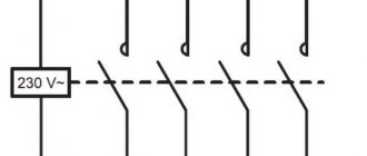
How much current does a 40-watt light bulb consume from a 220-volt network? Stop, stop, don't rush to answer. Let's add one more small condition: this light bulb is fluorescent ;). Well, is the answer still obvious? But sometimes even venerable (in appearance) electrical network specialists are unaware that such a lamp consumes a current of over 400 mA and an active power of almost 50 W! Is it possible to find out this with simple measuring instruments? Let's try to figure it out. As is known from the electrical engineering course, in the case of direct current, the total (also known as active) power consumed by the device is equal to the product of current and voltage: P = U×I This formula is also valid for alternating current, but with two reservations. Firstly, in this case, the current and voltage values must be rms. And secondly, the voltage and current curves must be in phase, which is observed only in the case of an active (resistive) load (Fig. 1): To find out the power in this case, it is enough to measure the current and voltage of the network with any multimeter and multiply the resulting numbers. Here it must be said that in everyday life there are not so many loads of a purely resistive nature. Along with the slowly but surely dying incandescent lamps, we can name only some heating appliances, irons, electric stoves and kettles. That's all, actually! But what about in other cases? And here power measurement becomes a rather non-trivial matter. The total power of any electrical appliance is still equal to the product of the effective values of current and voltage, but it is no longer what we are interested in. Since a household electricity meter measures (and accordingly charges for payment) only the active energy consumed, only the active component of power, which depends on many factors, is important to us. In the case of a purely reactive load, when the current and voltage curves are shifted in time relative to each other (Fig. 2): active power is determined by the formula P = U×I×cosφ where U , I are the effective values of voltage and current, respectively, and φ is phase shift angle between the corresponding curves. The difficulty in measuring power “with improvised means” in this case is that this angle is unknown in advance (although we can still find out U and I using a simple multimeter). The second difficulty is that there are not very many loads with a purely reactive nature of consumption in everyday life. Much more common is the so-called pulsed nature of consumption, in which the shape of the current curve is not sinusoidal (a classic example is an incandescent lamp turned on through a thyristor dimmer). In this case, the active power will also always be less than the product of the effective values of U and I , and the phase shift of these curves may or may not be present (Fig. 3): In this case, the active power can be calculated using the formula P = U × I × λ where λ is a general coefficient that takes into account both the phase shift between voltage and current and the distorted shape of the current, called the power factor. Obviously, for a active load λ = 1, and in the case of a purely reactive load λ = cos φ . It is worth noting here that for electrical appliances with the energy consumption pattern shown in Fig. 3, “improvised” measuring instruments are completely unsuitable. This is explained by the fact that inexpensive multimeters implement a simplified principle for determining the effective value of alternating current, designed only for its sinusoidal shape, which leads to significant errors. For correct measurements, it is necessary to use a device of the TrueRMS class, which also belongs to the appropriate price category :(. In addition, we still do not know the coefficient λ . How can we measure the power of an electrical appliance in the general case? One way is to use a conventional control electric meter for this purpose (Fig. 4): By connecting the load we are interested in through such a meter, after a certain period of time we will receive information about the electricity consumed, which will allow us to calculate the average power consumption.The disadvantages of this approach are low accuracy, a pronounced dependence of the measurement time on the load power, the impossibility of measuring characteristics of dynamic loads and determination of λ .
Device base
Having rejected the use of a conventional electric meter and leaving out the possibility of purchasing an expensive professional wattmeter, we will consider the possibility of building our own measuring device. First, we formulate the general requirements for it: • automatic measurement of active power in a wide power range, for example from 0.1 to 1000 W; • calculation of electricity consumed over a certain period of time (maximum – 1 day); • power measurement time no more than 2 seconds; • measurement accuracy is not worse than 1%; • the ability to measure the effective voltage value; • the ability to measure the effective current value (regardless of the shape of the curve); • calculation and display of power factor λ .
In the process of searching for a suitable solution, the author’s gaze fell on a series of microcircuits for electric meters manufactured by Analog Devices [1]. In addition, an article was discovered devoted to an amateur wattmeter in the magazine Everyday Practical Electronics [2] (unfortunately, the authors only implemented power and energy measurements in it). Despite the fact that the most suitable microcircuit for building the device turned out to be ADE7753, the final choice for a number of reasons (not the least of which was availability in Russia) was made in favor of ADE7756 [3]. According to the manufacturer's specifications, the ADE7756 chip is a programmable, high-precision electrical energy meter with a serial interface. Its block diagram is shown in Fig. 5: Signals proportional to the load current and voltage are respectively supplied to analog-to-digital converters ADC1 and ADC2 with a reference voltage of 2.4 V. The current signal is then digitally processed in a high-pass filter HPF1, and then multiplied with the voltage signal. The active power signal thus obtained is passed through a low-pass filter LPF2, after which it is accumulated in the active energy register AENERGY, the contents of which are accessible via the SPI serial interface. In addition, the same signal is supplied to the DFC converter, which generates a pulse (frequency) power indication output at the CF pin. The operation of the microcircuit is configured using current amplification registers (APGAIN), phase shift calibration of voltage and current (PHCAL), active power zero correction (APOS), and CF output frequency calibration (CFDIV). In addition to the SPI interface and the CF frequency output, there are also additional outputs ZX (synchronized with the zero crossing of the measured voltage) and SAG (activated when the input voltage drops unacceptable). The microcircuit is clocked by a quartz resonator with a frequency of 3.58 MHz, connected to the CLKIN and CLKOUT pins. To work with the microcircuit, it must be connected to an external terminal or microcontroller with an SPI interface. The work itself consists of reading and writing registers, a complete list of which is given in document [3]. An important feature for our case is the ability to read not only the energy accumulated over a certain period of time from the AENERGY register, but also instantaneous voltage, current and power values from the WAVEFORM register. This allows you to calculate all the necessary electrical characteristics of the load using a microcontroller.
Electrical diagram
As a result of familiarization with the materials [2], [3], [4] and [5], a schematic diagram of a wattmeter was developed, codenamed WH-756 (Fig. 6): The input circuits are built on the basis of the ADE7756 (DD2) microcircuit. A resistive shunt R7 with a resistance of about 25 mOhm is used as a current sensor. The voltage released on the shunt is supplied to the inputs V1N, V1P of the DD2 microcircuit through resistors R8 and R9, which together with capacitors C7, C9 form low-pass filters that cut off the influence of higher current harmonics on the measurement result. In a similar way, the mains voltage is supplied to the inputs V2N, V2P through dividers R2/R3 and R4/R5, the lower shoulders of which are bypassed by capacitors C3, C5. The DD2 chip is connected to a +5 V supply voltage, additionally filtered using capacitors C8 and C11. The same pair of capacitors (C10 and C12) is additionally connected to the reference voltage output. The microcircuit is clocked by a standard ZQ2 quartz resonator at a frequency of 3.58 MHz. The “heart” of the system is the control microcontroller DD1 type ATMega8535, operating at a frequency of 16 MHz provided by the ZQ1 quartz resonator. One of the microcontroller timers is used to count precise time intervals, which required the additional connection of a ZQ3 clock resonator with a rating of 32768 Hz. Microcontroller DD1 interacts with chip DD2 using a hardware serial interface SPI and asynchronous signals connected to port D. It should be noted that in the current implementation of the WH-756 device, the connection is between pin 11 of DD2 (CF) and pin 20 of DD1 (PortD.6) is not used and can be omitted. The CF DD2 output is used only for visual indication of power measurement using the HL2 LED. The device is controlled using four buttons SB1-SB4, codenamed “Left”, “Right”, “Up”, “Down”. Each button performs a function depending on the current operating mode. The measured values and other information are displayed on a standard sign-synthesizing LCD indicator HG1 (16x2) with a HD44780 series controller and backlight. The indicator contrast is adjusted using trimming resistor R14. The measuring part of the circuit is powered from the network through transformer T1 with fuse FU1, diode bridge VD1-VD4 and stabilizer DA1. The power part is connected through fuses FU2 and FU3, the simultaneous removal of which allows you to completely isolate the low-voltage part of the circuit from the mains voltage. ATTENTION! The device circuit has a direct galvanic connection with the wires of the 220/230 V electrical network. All installation and electrical safety rules applicable to circuits of the corresponding voltage must be observed. Extreme care and caution must be exercised when connecting the device!
Working with the device
The WH-756 AC wattmeter has two main operating modes, which can roughly be called electric meter mode and wattmeter mode. When turned on, the device displays a startup screen containing its name and information about the developer. Pressing the “Left” button allows you to turn the screen backlight on or off, the remaining buttons switch the device to the first operating mode. In this case, the screen will take the form shown in Fig. 7: In the “electricity meter” operating mode, the first line of the screen displays the time of the current measurement and the current power of the connected load. When entering this mode, the measurement time and accumulated energy counter are automatically reset to zero. The bottom line displays the amount of electricity consumed, as well as the average power during the measurement time. Information on the screen is updated in this mode once per second. After 23 hours, 59 minutes and 59 seconds, the measurement is automatically paused and the information is recorded on the screen. In order to restart (reset the results) of the measurement, you must press the “Right” button. The Left button switches the indicator backlight. The transition to the second measurement mode is made by pressing the “Down” button. In the “wattmeter” operating mode, the first line of the screen contains the measured values of the network voltage and load current (Fig. 8): The bottom line shows the values of the load active power and power factor λ (PF). Information is updated on the screen once every 2 seconds. It should be noted here that, due to the characteristics of the microcircuit used, the voltage and current measurements are made in successive cycles of 1 second, therefore, when measuring loads with a rapidly changing current, as well as with a rapidly changing network voltage, some error in the calculation of λ . Also, due to the undocumented features of the DD2 microcircuit, correct measurement of current and power factor is carried out only at currents above 5-10 mA (although active power is measured correctly at lower currents!). In order to “freeze” information on the screen or resume updating it, use the “Right” button in this mode. Pressing the Down button takes you to the help screen, and the Up button returns the device to the first operating mode. All buttons must be held after pressing for no more than 2 seconds until the required action is completed. The help screen (Fig. 9) contains information about the current temperature of the DD2 chip and the firmware version: From here you can return to the “vat” modes (by pressing the “Up” and “Down” buttons, respectively). Controlling the backlight using the Left button also works. Please note that the screen backlight automatically turns off 10 minutes after entering any device screen. This is done to reduce the load on the power supply, since the backlight consumes a current many times higher than the consumption of the rest of the circuit.
Calibration
Like any metrological device, to achieve sufficient measurement accuracy, the WH-756 wattmeter requires preliminary calibration. Calibration information is written to the EEPROM of the DD1 microcontroller and does not require frequent updating. To facilitate calibration, the device has several special functions, the first of which is automatic zeroing of voltage and current. To call this function, in the “wattmeter” operating mode, with fuses FU2 and FU3 removed, wait for the readings U and I , then press and hold the “Left” button until the readings are reset to zero. If necessary, this operation can be repeated several times until stable zero voltage and current values are achieved. The next step is to calibrate the displayed values in real units using a set of calibration screens. The first of them is called up from the third (reference) main screen by pressing the “Right” button. The top line shows the measured power value in arbitrary units, and the bottom line shows the value in watts calibrated using the current coefficient (for reference). This information is needed to calculate the calibration coefficient KP using the formula: KP = P / Pact where Pact is the actual load power (in watts), P is the power in conventional units from the first line of the screen. Similar coefficients for current and voltage KU and KI on the second and third calibration screens are calculated using the formulas KU = Uact / U KI = Iact / I It is recommended to perform calibration on an active load with known parameters, for example, using a set of incandescent lamps with a power of 10 to 500 watts . The KP , KU and KI values are written to the EEPROM of the DD1 microcontroller in Single format.
Housing, parts
The author's version of the WH-756 device is assembled in a universal plastic case of type 15-2(B3) with dimensions of 150x120x40 mm (Fig. 10): The front panel of the case contains buttons SB1-SB4, the CF indicator and the HG2 screen. A standard two-pin socket is fixed at the top, to which the loads under study are connected. It is important to note that this outlet is directly connected to the power cord through fuses FU2 and FU3 and is not switched by the device's power switch. Switch SA1 and fuses FU1-FU3 are installed on the rear panel (Fig. 11): Since the device was manufactured in a single copy and its serial production was not intended, a printed circuit board was not developed for it. The parts are installed on a breadboard measuring 110x50 mm, the appearance of which (without a shunt, power supply and indicator) is shown in Fig. 12: Microcircuits in DIP packages are installed on mounting panels, resistors and capacitors are packaged. All resistors, except R2, R4 and R7, are of the MLT-0.125 type. Resistors R2 and R4 for a voltage of at least 250 V and a power of 1 watt. Shunt R7 is made up of four parallel-connected resistors of the SQP-15W type with a nominal value of 0.1 Ohm each. The maximum possible heating of this shunt in real conditions is not capable of having any effect on the accuracy of measurements. Connector J1 is intended for in-circuit programming.
Conclusion
An accurate digital meter that measures power, voltage, current, and power factor of network loads, allowing you to evaluate the energy-saving potential of various personal devices. For example, when taking measurements, the author found out that one of the TVs in standby mode consumed more than 10 watts, that is, it wasted almost half the power usefully consumed by a home NAS server! Of course, this allows us to draw conclusions about the need to completely disconnect such loads from the network when they are not in use. In general, among the measurement results there were so many indicative and even sometimes unexpected numbers that it deserves a separate article. Literature, sources
1. https://www.eltech.spb.ru/techinfo.html?aid=27 2. Clarke, J. Control your power costs with the Energy meter // Everyday Practical Electronics, 2007. No. 5, pp. 12-21, No. 6, pp. 52-61. 3. https://smd.hu/Data/Analog/ADE77xx/ADE7756/ADE7756_0.pdf 4. https://www.analog.com/static/imported-files/application_notes/an564.pdf 5. https:// www.analog.com/static/imported-files/application_notes/AN578_a.pdf
Files: Firmware version 4.4 + EEPROM
All questions in the Forum.
| What do you think of this article? | Did this device work for you? | |
| 30 | 2 | 0 |
| 1 | 0 |
Connecting a digital voltammeter
How to properly connect an electric meter to the wires
There is an interesting digital DC module that combines the functions of a voltmeter and an ammeter in one device. Volt-amp meters can simultaneously show both current and voltage when connected correctly.
An example of such a device is model DSN-VS288, consisting of:
- the measuring device itself;
- 2-wire cable (ammeter input and output);
- 3-wire cable (device power supply and voltage measurement).
Voltammeter DSN-VS288
Measuring range of the amperevoltmeter:
- from 0 to 100 V voltage,
- from 0 to 10 A current.
Since the supply voltage of the device is 3.5-30 V, its connection circuit differs:
- If it is necessary to connect the device to a circuit whose voltage lies between 3.5 and 30 V, the general power supply is also used for the device. The black wire of the 2-wire cable goes to the negative, the red wire to the load and from the other load terminal to the positive. On a 3-wire cable: yellow and red are connected together at the “plus” of the source, and black remains free;
- If the power supply voltage is greater or less than the power supply range of the device, then a voltammeter must be connected to an individual power supply. A two-wire cable is connected in the same way; for a three-wire cable, red and black go to the “plus” and “minus” of their IP, and yellow goes to the “plus” of the main IP.
Connection diagrams DSN-VS288
Each type of ammeter is connected according to the same principle, but with the obligatory consideration of the quantitative value of the measured current and the selection of appropriate devices and devices for this.
Design features
There are several types of devices that are structurally different from each other. They serve to measure alternating and direct current. According to their principle of operation, ammeters are:
- electromagnetic;
- magnetoelectric;
- thermal;
- electrodynamic;
- detector;
- induction;
- photo- and thermoelectric.
A pointer is connected to the frame, which moves along the ammeter scale and shows the current value. In an electrodynamic device, the main parts are moving and stationary coils. They can be connected to each other either in series or in parallel.
The currents passing through them interact with each other, and the moving coil connected to the arrow is deflected. If a large current is measured using an ammeter, it is connected through a transformer.
Determining the amount of motor slip
The predetermining moment in direct dependence on slip is the initial value of the moment when the electric motor remains stationary. The maximum slip value is called critical.
Specific calculations are made by specialists from the manufacturer, and they are indicated in the relevant technical specifications attached to the electric motor upon purchase. When the active resistance of only the rotor increases, the critical slip value increases and the shaft rotation speed decreases. These parameters can be changed by using additional resistance, which is introduced into the rotor winding circuit.
Block connection diagram
Almost all of them are small-sized and can be installed in small power supply cases. Here Aliexpress very often lends a helping hand, promptly supplying Chinese digital measuring instruments.
But for beginners, commissioning connecting an ampere-voltmeter to the circuit can be a problematic task, because the segments glow quite brightly, the color scheme is chosen very well.
Measured voltage V; current A.
And the output current easily reached almost one ampere. Connection Using a voltmeter, you can measure the current voltage in the power supply network.
For a small fee, you can find out whether the equipment works in suitable conditions. Once power is supplied to the circuit, the indicator will light up. Almost a twin of the previous voltmeter, it differs in the marking of the wires and at a reduced price.
If the connection is incorrect, the device display will show zero values. Once power is supplied to the circuit, the indicator will light up.
In order for it to start measuring voltages less than 3 Volts, you need to unsolder the jumper resistor R1 and apply voltage B from an external source to its right-hand contact pad in the diagram; higher voltage is possible, but not advisable - the DA1 stabilizer gets very hot. Since this information is not available on the seller’s page, I had to scour the web and sketch out a couple of diagrams. Thick wires: black minus ammeter, red ammeter output. It will be enough to connect the charger, where the voltammeter is installed, to the battery, and we will see what voltage is currently on it. Sometimes there are ammeters without a built-in current-measuring shunt.
A simple and beautiful technical solution. The lower limit is 0.1 V and 0.01 A. Since this information is not on the seller’s page, I had to rummage through the network and sketch out a couple of diagrams. The fact is that if you connect a voltmeter-ampmeter to the regulated output of the power supply, then when the voltage drops below 4. Not everyone will immediately understand which wire needs to be connected where, and the instructions are usually only in Chinese. How to connect a Voltammeter DC 100v 10a part 2
For my charging, I bought a curious copy of a Chinese voltmeter-ampmeter; I picked it up at the market and didn’t really look at it, but when I brought it home, I was scratching my head for three days about how to connect it, because I couldn’t find anything similar on the internet. I found a general description with a crooked translation on the avrobot website. ru/product_info.php?products_ >
“Connection instructions:— Red thin wire (vcc): Device supply voltage + 3.5-30 V (Note: if the measured signal is less than 30 V and have a common power supply minus, then the measured signal can also be used to power the device)— Black thin wire (ground): Supply voltage “-“, “-” measured signal 3.5-30 V— Yellow thin wire (vin): Measured signal “+” (0-100 V)— Red thick wire (i +): Current input “+” (in the power supply series are positive)— Black thick wire (i -): C. Current input “-” (Negative power wire) Calibration instructions: Due to the influence of temperature and changes in the parameters of electrical components over time, non-zero readings may appear when measuring, which is normal. This is not an error or malfunction. Solution: When the instrument is disconnected from the power, please short-circuit terminals A and B. Then take an electricity measurement, the instrument will automatically calibrate to zero. After finishing the automatic calibration, please disconnect A and B. After this, use the device as normal."
On the back wall there is an MC74HC5950 microcircuit, there are two thick wires and three thin ones. Below are photos and comments.
Chip CA3162E
BY42A can also be found in two board versions, but the color marking of the wires remains the same. To reduce the influence of ambient temperature on measurements, the additional resistor is made of a material with a low temperature coefficient of resistance. The connection can be made through a special socket connector, or using soldering. They contain a converter of the input signal into the angle of rotation of the arrow, showing on the scale the value of the measured voltage.
To also reduce the temperature factor during measurements, an additional resistor made of the same kind of material is connected in series with the ammeter coil. Connection Using a voltmeter, you can measure the current voltage in the power supply network.
It is clear that a couple of amperes can be easily measured with a regular cheap multimeter, but what about 10, 15, 20 or more amperes? The scale readings are also multiplied by n. Homemade automobile voltmeter on microcircuits. If the connection is incorrect, the device display will show zero values. Receiving and transmitting alternating current is much easier than direct current: there is less energy loss. With the help of transformers, we can easily change the alternating current voltage.
CAE microcircuit for digital voltmeter and ammeter There are other microcircuits of similar action. Instrument transformers are depicted in the diagrams as ordinary transformers. A nuance when connecting a Chinese voltmeter and ammeter
See also: How to measure a phase zero loop
AC Electricity Measurement
Any household appliances powered from the mains show the load with which they consume alternating current. When considering issues of energy use, it is worth remembering the concept of power, for which the final payment is made in kilowatts. In this case, the ammeter acts as a device for performing indirect measurements. In this way, the current strength is determined through the standard formula according to Ohm’s law:
P=I*U, where:
- U is voltage;
- I represents the current;
- P indicates the calculated power.
There are cases when information recorded by the electrical panel is lost. To restore the necessary parameters you will need an ammeter. Sometimes, when servicing a large building, it is not possible to control all the devices that record electricity. The problem is solved by connecting an amplified ammeter to the output of the panel and taking the required measurements. Such tasks should only be performed by specially trained people.
Types of electrical measuring instruments
Classification of electrical measuring instruments:
By type of current:
- variable;
- permanent;
- combined devices.
By level of accuracy:
- 0, 05;
- 0,1;
- 0,2;
- 0,5;
- 1,0.
Each number indicates a percentage of the permissible error.
According to the essence of the work:
- electromagnetic;
- induction;
- magnetoelectric;
- ferromagnetic.
When carrying out measurement tests, it is necessary to select the appropriate measuring device correctly.
- Ammeters are devices for measuring current values. The unit of measurement is Ampere (A).
- Voltmeter – measures the voltage of the electrical network. The unit of measurement is Volt (V).
- An ohmmeter is an auxiliary device that measures resistance in an electrical circuit. Measured in Ohms (Ohm).
- A wattmeter is an element that measures network power. The unit measured is Watt (W).
- Frequency meter – a frequency meter for alternating pulse values. Measured in Hertz (Hz).
Device and principle of operation
If we talk about the principle of operation, then all devices of this type that allow various measurements in electrical networks are of 2 types:
- electromechanical type;
- electronic.
The first category is pointer devices. In them, the arrow is attached to a special frame where the cable is wound. Such a coil will be located next to the magnet in those devices that are usually used for DC networks. Or next to another coil - if the device is intended for alternating current.
But if you use a diode bridge for connection, then it will be able to carry out the necessary measurements in the AC network, but with a slight loss of accuracy.
When an electric current passes through the winding, an electromagnetic field appears in it, which interacts with a magnet or another winding, and the frame rotates. The coil where the arrow is located is prevented from rotating by a spring. For this reason, the angle of rotation of the frame will correspond to the current that flows through it and the potential at the terminals.
It can be a piston type, made of a cylinder and piston, or made of an aluminum plate. To increase the accuracy of the readings, the arrow has special counterweights, which reduce the influence of gravity to zero. And the system itself is made of a type of steel such as alloy steel to reduce its wear.
The sensitive element in electronic analogs is an electronic board that transforms the incoming signal into instrument readings. This device can operate either from the voltage that is measured, or from batteries or external power. Electronic voltmeters themselves are divided into 2 categories:
- analog;
- digital.
In devices belonging to the first category, there is a converter of the incoming signal into an angle of arrow rotation, which shows the value of the voltage being tested, which is displayed on the scale. The disadvantage of such devices is the need to recalculate the scale readings if the measuring limit changes.
The digital voltmeter is equipped with an appropriate display, as well as a converter, thanks to which the signal takes on a digital form. If the device is connected to a network where direct current is present, the polarity of the connection can be seen on the display. The distinctive features of such a device will be compactness and accuracy. True, the last point will depend on the model of the built-in controller.
Principle of operation
Hole measurement
The first device was invented by Schweiger at the beginning of the 19th century, but it was then called a galvanometer. A drawing of a simple ammeter looks like this. On the axis of the bracket there is a steel anchor with an arrow. This structure is located parallel to a permanent magnet, which acts on the armature and gives it magnetic properties.
Lines of force run along the magnet and the arrow, which corresponds to the zero position on the scale. As soon as electric current begins to flow through the bus, a magnetic flux will be formed. Its field lines will be located perpendicular to the lines of the permanent magnet.
DIY shunt
It is not recommended to wind the wire (or enamel wire) spirally - the inductance of the resulting coil will reduce the accuracy of the ammeter. Coil shunting has the disadvantage of suppressing current surges, especially in the case of a throttled (with a core) coil. If the piece of wire is too long, arrange it in the form of a wavy “snake”.
Any insulator is suitable as a dielectric - from ceramic to textolite. In addition, a wire twisted into a coil can overheat the dielectric, which cannot withstand elevated temperatures of more than 150 degrees. And only ceramics and tempered glass are resistant to overheating.
- First, a dielectric plate is cut out, in which holes are drilled for bolts with washers and nuts. Material – textolite, getinaks, wood or composite materials.
- To significantly insulate the heat of the wire from the supporting plate, ceramic rings are installed on the bolts. After them, washers are placed that clamp the wire.
- To prevent spontaneous unwinding and loss of wires and wires, locking washers are placed in front of the nuts.
- Finally, the wires and wire ends are inserted between the washers and the nuts are tightened.
How to connect a digital voltmeter and ammeter (Chinese module) to the power supply with your own hands.
Topic: how to install a current and voltage meter on a power source.
It is quite convenient when the power supply has an indicator showing constant voltage and current. When powering a load, you can always see the voltage drop and the amount of current consumed. But not all power supplies are equipped with ammeters and voltmeters. Purchased, more expensive power supplies have them, but cheap models do not. And they are not always installed in homemade power supplies. Today it is possible to purchase for little money a digital module measuring a constant current and voltage indicator (Chinese voltmeter ammeter). This module costs around 3 bucks. You can buy it by parcel from China, at the nearest radio market, electronic components store.
This Chinese digital voltmeter, ammeter module itself measures direct current (up to 10, 20 amperes, depending on the model) and voltage (up to 100, 200 volts). It has small, compact dimensions. It can easily be mounted in any suitable housing (you need to cut the appropriate hole and just insert it there). On the back of the board there are two trimming resistors that can be used to correct the readings of the measured values of current and voltage. The accuracy of this digital Chinese voltmeter and ammeter module is quite high - 99%. The screen has a three-character display in red (for voltage) and blue (for current). This unit is powered by DC voltage from 4 to 28 volts. Consumes little current.
The installation itself, the electrical connection to the power supply circuit, is quite simple. The current and voltage measuring module has the following wires: three thin wires (black minus and red plus for powering the module, yellow for measuring DC voltage relative to any black), two thick wires (black minus and red plus for measuring DC current).
This Chinese ammeter and voltmeter module can be powered either from the source itself, on which we measure electrical quantities, or from an independent power supply. So, after mounting it into the meter body, we solder together two black wires (thin and thick), this will be a common minus, which we solder to the minus of the power supply. We solder together thin red and yellow wires and connect them to the output (plus) of the power source. We connect the electrical load itself to the thick red wire, relative to the soldered black wires (these will be the output wires of the power supply).
It is important to note that the polarity of the current leads is important for correct DC current measurements. That is, it is the thick red wire that should be the output of the power supply
Otherwise, this digital ammeter will show zeros on its display. On a regular power supply (without voltage regulation function), the indicator can only monitor the voltage drop. But on an regulated power source it will be clearly visible what voltage you currently have when you set it.
Video on this topic:
PS In general, connecting this digital Chinese voltmeter and ammeter module should not be difficult. The next time you use it, you will appreciate its performance and you will like it. The three-character measuring unit is considered the most popular, although the four-character one, whose measurement accuracy is no longer 99%, but 99.9%, will be a little more expensive. These digital modules that measure direct current and voltage are also of a separate type, that is, one such unit is either an ammeter or a voltmeter. They have a bigger screen.
Ammeter - measuring current: purpose, connection diagrams, types
An ammeter is an electrical measuring device designed to record the strength of direct or alternating current flowing in a circuit - that is, a device for measuring current. The ammeter is connected in series with the section of the electrical circuit where the current is supposed to be measured. Since the current that it measures depends on the resistance of the circuit elements, the resistance of the ammeter should be as low as possible (very small). This allows you to reduce the influence of the current measuring device on the measured circuit and increase their accuracy.
The instrument scale is calibrated in µA, mA, A and kA, and depending on the required accuracy and measurement limits, a suitable device is selected. An increase in the measured current is achieved by including shunts, current transformers, and magnetic amplifiers in the circuit. This allows you to increase the limit of the measured current value.
Electrical voltage measurement process
When working with electrical appliances, special care must be taken. Any sudden movement may cause a short circuit. What to consider during the workflow? Safety precautions include several simple rules:
Correct fixation of the probes. When testing the voltage, it is necessary to hold the measuring parts safely. You should not touch them to each other. It is not recommended to touch the probes when connecting the voltmeter to an electronic circuit. This may cause a short circuit.
The black probe is installed to one of the parts of the DC conductor. Voltage drops can be correctly measured in a parallel position of the meters.
The red probe makes a tangential movement. If the device has a maximum voltage, its exact values will appear on the device.
The maximum measuring range is set on the device. If there are any problems in the electrical circuit, then note the active movement of the arrow towards the high mark.
When the research has come to an end, they move on to deciphering it.
Scope of application of ammeters
Instruments for measuring current have found application in various fields. They are actively used in large enterprises associated with the generation and distribution of electrical and thermal energy. They are also used in:
But not only medium and large enterprises use this device: they are also in demand among ordinary people. Almost any experienced auto electrician has a similar device in his arsenal, which allows him to measure the power consumption of devices, car components, etc.