Electrical energy on an industrial scale cannot be transmitted in the form of single-phase alternating current. For this purpose, three-phase current is used, and three-phase transformers are used for its transmission. One of the ways to transform three-phase current is the use of three single-phase transformers.
The connection of the primary and secondary windings in these devices is carried out in one of the three-phase systems - star or delta. It is on this principle that powerful single-phase transformers operate, which are equipped in large power plants. Their primary windings are connected to the corresponding phases of the generators, and the secondary windings, connected in a star, are connected to the corresponding phases of the power lines.
Electrical device design
Transformation of three-phase current does not necessarily imply the use of one transformer having a common magnetic circuit. Although such installations are widely used in the national economy.
There is the possibility of such a transformation using three separate single-phase transformers that are not magnetically connected to each other, that is, each individual phase will have its own separate magnetic circuit.
A transformer made according to this scheme is called a group transformer. The primary and secondary windings of the device are interfaced with each other according to one of the schemes adopted for transforming three-phase current.
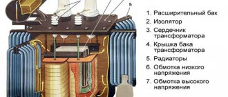
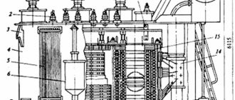
Structurally, a three-phase transformer is a three-rod magnetic circuit with windings located on each of the rods, made in the same way as for single-phase devices.
Interesting material on the topic: how a toroidal transformer works.
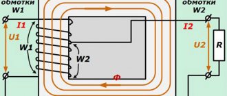
Let's imagine three single-phase transformers placed next to each other so that their three rods form one common central rod. On each of the other three rods there are primary and secondary windings.
The currents in the transformer coils will create time-varying magnetic fluxes, which will each be closed in its own magnetic circuit. In the central composite rod, the magnetic fluxes will add up and give a total of zero, because these fluxes are created by symmetrical three-phase currents, regarding which we know that the sum of their instantaneous values is equal to zero at any moment of time.
Let us assume that the primary coils of all transformer bars are exactly the same and wound in the same direction. We connect all the upper ends of the coils to neutral O, and connect the lower ends of the coils to the three terminals of the three-phase network. The magnetic cores are made of sheet electrical steel. To weaken eddy currents and reduce magnetization reversal losses, steel sheets are insulated with varnish before assembly.
Detailed design of a three-phase transformer.
Parallel connection
Connecting secondary windings
Parallel connection of identical secondary windings allows you to increase the power (current) at the output of the device. This way it is possible to increase the efficiency and load capacity of the serviced line.
When using this approach, you will need to take into account one important detail related to the order of connection of the secondary windings. To obtain the expected results, the windings must be turned on in phase, which means connecting the same type of ends of all three coils at one point. If this rule is violated, the voltage at the output of two windings connected out of phase will be close to zero (the substitution principle applies). When this error is made when turning on a transformer, its power and efficiency are significantly reduced. If, during a secondary check, it is discovered that the voltage has not changed compared to a single connection, then the coils are connected in phase.
A converter device, defined as a 220 to 380 Volt 3 phase transformer, can be obtained if a special circuit is used to increase the output voltage. Its peculiarity is the presence of one primary and three secondary windings connected in a star or delta circuit.
Magnetic Circuit Location
Three-phase core transformers are divided into transformers with a symmetrical magnetic circuit and transformers with an asymmetrical magnetic circuit. The arrangement of the rods in the same plane leads to the fact that the magnetic resistance for the middle phase flow is less than for the outer phase flows.
Indeed, the magnetic fluxes of the extreme phases travel along slightly longer paths than the flux of the middle phase. In addition, the flow of extreme phases, having left their rods, passes completely in one half of the yoke, and only in the other half (after branching into the middle rod) does half of it pass. The flow of the middle phase, upon exiting the vertical rod, immediately branches into two halves, and therefore only half of the flow of the middle phase passes through both parts of the yoke.
Thus, the flows of the extreme phases saturate the yoke to a greater extent than the flow of the middle phase, and therefore the magnetic resistance for the flows of the extreme phases is greater than for the flow of the middle phase.
A consequence of the inequality of magnetic resistances for the flows of different phases of a three-phase transformer is the inequality of no-load currents in individual phases at the same phase voltage. However, with low saturation of the iron of the yoke and good assembly of the iron of the rods, this inequality of currents is insignificant.
Since the design of transformers with an asymmetrical magnetic circuit is much simpler than that of a transformer with a symmetrical magnetic circuit, the first transformers found their primary application. Transformers with a symmetrical magnetic circuit are rare.
It will be interesting➡ Necessary conditions for parallel operation of transformers
Main types of device
The main group of three-phase transformers are armored transformers. An armored three-phase transformer can be considered as consisting of three single-phase armored transformers, placed one next to the other with their yokes. It can be divided into three single-phase armored transformers, the magnetic fluxes of which can each be closed along its own magnetic circuit.
In core transformers, the windings are almost entirely open and therefore more accessible for inspection and repair, as well as for the cooling medium. There are a number of advantages and disadvantages based on which type of transformer is chosen.
Pros and cons of armored transformers over rod transformers.
The devices are switched according to various winding connection schemes. Group three-phase transformers are used in the presence of very high powers, from 630 kVA per phase.
Using a group transformer under such conditions is advisable because the dimensions and weight of the product are significantly smaller than a similar unit operating at the total power of the group.
Moreover, when using a single transformer, in order to have reserve power, you have to install another similar device, and in a group transformer, one of three single-phase ones can be used as a backup.
This determines the choice of group transformers for the stated purposes, despite the fact that they have lower efficiency, larger dimensions and are somewhat more expensive compared to single analogues.
You can read more about the design of transformers in the material on current transformers.
Purpose and types
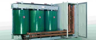
Three-phase transformer
The classic station three-phase power transformer is used to convert high-voltage energy into a form convenient for the consumer. A high voltage (6.3-10 kilovolts) is supplied to its primary windings, and the output is 220 Volts, which are more convenient for everyday use. This value is measured between the phases and the neutral conductor of the transformer, called the neutral. It is usually designated as phase voltage, in contrast to linear 380 Volts, counted between each phase.
Three-phase step-down transformers of this class provide current transmission from the local substation through an underground cable or power line directly to the end consumer. For these purposes, a special 4-core cable in an armored core or an overhead wire of the SIP brand is used. Through them, electrical energy is delivered directly to its destination - to the input and distribution devices of the serviced territories and facilities.
According to their functional purpose, 3-phase transformers are divided into the following classes:
- linear (station) devices;
- special converting units.
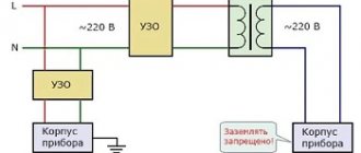
Particularly noteworthy are three-phase isolation transformers used for decoupling electrical circuits and power circuits.
Test transformer
Special devices are divided into the following types:
- Test transformers. These include three-phase autotransformer systems.
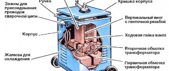
- Devices used to power special equipment: welding units, in particular.
- Balancing transformer units.
The first two types are used for research purposes. Three-phase balancing transformers are used to eliminate phase imbalance that occurs in electrical networks due to uneven load distribution.
In electrical engineering there are also variants of two-phase transformers, often used in electronic circuits and automation devices. They are designed so that the two output voltages are shifted relative to each other by 90 electrical degrees. Most often, such electrical solutions are used in welding equipment.
Rod type magnetic core
To power radio-electronic devices, three-phase transformers with a common magnetic system through a yoke I for three phases with three rods C, or three-rod transformers are usually used. Each of the transformer windings, both primary and secondary, can be connected: a) by a star; b) a triangle.
When connected by a star, the ends of the windings form a common point 0. When connected by a triangle, the beginning of the first phase winding is connected to the end of the third, the beginning of the second - to the end of the first, and the beginning of the third - to the end of the second. In the first case, everything starts, and in the second, the common points of the windings are connected to the network.
It should be noted that the concepts of the beginning and end of the windings are conventional, but they are necessary for the correct connection of the phase windings. In three-phase transformers, the positive direction of the current from the beginning to the end of the winding must correspond to a certain direction of the magnetic flux in the rods; in core transformers this direction must be the same.
Winding connection: a - star; b - triangle.
The beginnings of high voltage (HV) phase windings are usually designated by capital (capital) letters A, B and C, and their ends by letters X, Y and Z, and for phase windings the letters AX, VU and CZ are used. The beginnings and ends of low voltage (LV) windings are designated, respectively, by lowercase (small) letters - a, b, c and x, y, g.
The most common winding connections are “star” (Y) and “delta” (D), and the primary and secondary windings can have either the same or different circuits. If, when connecting the windings with a star, the zero point is output, then such a connection is called “star with zero” (Yo).
Star connection of windings
The simplest and cheapest of them is to connect both windings of the transformer with a star (Y/Y), in which each of the windings and its insulation (with solid grounding of the neutral point) should be designed only for phase voltage and line current.
Star connection of transformer windings.
Since the number of turns of a transformer winding is directly proportional to the voltage, therefore, a star connection of the windings requires a smaller number of turns in each winding, but a larger cross-section of conductors with insulation designed only for phase voltage.
A three-phase transformer has windings connected in a star (Y/Y). This connection is widely used for small and medium power transformers (up to approximately 1800 kVA). The star connection is most desirable for high voltage, since in it the insulation of the windings is calculated only for the phase voltage. The higher the voltage and lower the current, the relatively more expensive it is to connect the windings with a delta.
Where is triangle winding used?
Connecting the windings with a triangle is structurally more convenient at high currents. For this reason, the Y/D connection is widely used for high power transformers where a neutral wire is not required on the low voltage side.
With three-phase transformation, only the ratio of phase voltages U1ph/U2ph is always approximately equal to the ratio of the numbers of turns of the primary and secondary windings w1/w2; As for linear voltages, their ratio depends on the method of connecting the transformer windings.
Connection of transformer windings with a triangle.
With the same connection method (Y/Y or D/D), the ratio of line voltages is also equal to the transformation ratio. However, with different connection methods (Y/D or D/Y), the line-to-line voltage ratio is √3 times less or more than this ratio. This makes it possible to regulate the secondary line voltage of the transformer by correspondingly changing the method of connecting its windings.
The operating characteristics of transformers are influenced by energy losses during heating of the windings in combination with other external and internal factors that significantly complicate the relationship of the secondary voltage shape with similar parameters of the primary circuit.
for “Three-phase transformer”
- Denis
:V
There is a three-phase voltage transformer with a star-star connection circuit with zero. But in the secondary circuit a circuit with an isolated neutral is used. Is it possible to use this transformer without connecting anything to its neutral, i.e. leave it “hanging” in the air?
Answer
Admin
:
V
If the load removed from the transformer is symmetrical, then you can...
Answer
:
V
There is a welding transformer with a 380/220 volt switch. I only used it on 220 volts. Will connecting it to three-phase voltage be better for cooking?
Answer
- Admin
:
V
If you have a 220-380 device, this means that not three phases can be supplied, but simply by switching the tap of the winding, you can supply either: Phase, plus zero. or Phase plus Phase.
Answer
:
V
If you connect it to two phases, that is, supply 380 volts, then it will cook the same way, since the frequency of the welding half-wave will remain the same. And now your device will consume the same power from the network, but the cross-section of the network wire can be reduced by one and a half times, since the current will flow 1 and seven tenths times less.