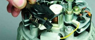
I thought about this thing last winter, when short trips around the city (home-work, home-shop, etc.) with all consumers turned on began to make themselves felt. Many people have probably heard about installing a “boost diode on the voltage regulator,” and so, after reading this article, I thought: in this situation, the voltage in the on-board network is not manually regulated, it simply becomes greater by the value by which the voltage drops when current passes through a diode. First, a little theory: when current passes through a diode, the voltage drops by an average of 0.5 volts (depending on the diode), and the standard regulator thinks that the voltage has dropped in the on-board network and makes the generator produce more voltage. Practice: we take the same circuit as for the “boost diode” and add to it a second diode and a 3-position switch, and you can use any diode, just so that it is designed for a current of at least 5A, then we assemble everything like this scheme
And voila first position 14.2 V, second position 15.4 V, third position 14.8 V
The voltage stabilizer in the on-board electrical system of a car is the most important component without any exaggeration. Not only the stability and longevity of the battery will depend on the quality of its work. At the same time, even a completely serviceable stabilization device does not always guarantee compliance with the voltage and quality of power supply of the vehicle’s electrical network. Car enthusiasts often wonder how to make the generator voltage regulator relay more reliable - contact a service station specialist, assemble or improve it yourself? There are many options.
Modern stabilizers
On modern vehicles, as a rule, self-oscillating relays are installed. They work on the principle of turning off the power to the excitation coil when the voltage reaches the upper limit of 13.5-13.8 V and connecting at the lower voltage threshold of 14.5-14.6 V.
Thus, the output voltage fluctuates constantly. Theoretically, this is not considered a disadvantage, since the voltage does not exceed acceptable limits. Still, this is not entirely safe. Surely experienced drivers know that the weak point of this type of relay is the transition moments when the rotor speed or load current changes sharply. A particularly unfavorable moment occurs with a large load current at low speeds. At these moments, voltage fluctuations often exceed the upper threshold. Due to the short duration of such surges, the battery will not fail immediately, but each time its capacity and, accordingly, resource is reduced.
This problem is solved in different ways. Sometimes car enthusiasts simply replace the self-oscillating relay with an outdated contact-vibration relay. A more optimal solution would be to replace the relay with a pulse-width stabilizer or upgrade the “native” one with the help of small additions.
The simplest DIY electric motor speed controller
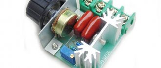
When making various homemade products, you have to face a number of problems and find solutions for them. This is the case with various devices that have a commutator electric motor in their design. Very often it is necessary to make the engine have adjustable speed. For these purposes, an engine speed regulator (controller) is used, which you can assemble yourself.
The regulator presented below for electric motors allows not only to ensure a smooth start of the motor and the degree of speed control, but also to protect the motor from overloads. The controller can operate not only from 220 Volts, but also from reduced voltage, up to 110 Volts.
SHI stabilizer
Pulse-width stabilizers are characterized by more stable operation, that is, an almost constant voltage is supplied to the vehicle network, and small deviations within the normal range are smooth. The device circuit uses the same parts as in the original, but at the same time the K561TL1 microcircuit is included. This made it possible to assemble a multivibrator and a short pulse shaper on the 1st node. The output switch control unit has also been simplified due to the use of a field-effect transistor with increased power.
Stabilizer operation cycle
When the ignition is turned on, a low logic level appears at the output of trigger DD1.1. As a result, transistor VT1 opens with the charging current of the capacitor SZ. It, in turn, begins to supply a high level to the inputs of element DD1.2, simultaneously discharging capacitor C4. When a low level appears at the output, DD1.2 opens the field-effect transistor VT3. The current from the stabilizer output flows through the excitation winding of the generator.
After the pulse stops, a high level is formed at the output of DD1.1 and transistor VT1 closes. Capacitor C4 is charged by the current passing through resistor R5 from the generator, which is controlled by transistor VT2. While the voltage on capacitor C4 drops to the lower switching limit of trigger DD1.2, it will switch. A high level will appear at its output, which will close transistor VT3. In order to protect the input circuits of the DD1 microcircuit, the voltage of capacitor C4 is limited by the diode VD4, which, when it is subsequently charged, will not lead to switching DD1.2. When a low-level pulse is again formed at the output of the generator, the process begins to repeat.
Thus, stabilization is carried out by the duration of the on state of the field-effect transistor, and the process is controlled by a measuring device, as well as a current generator. When the voltage at the generator output increases, the collector current of transistor VT2 increases. As the amperage increases, capacitor C4 begins to charge faster and the duration of the on state of transistor VT3 decreases. As a result, the current that flows through the excitation winding of the generator decreases and, of course, the output voltage of the generator decreases.
When the voltage at the output from the generator decreases, the current at the collector of transistor VT2 decreases. As a result, the charging time of capacitor C4 increases. This leads to a longer period of switching on of the transistor VT3 and the current that flows through the excitation winding of the generator increases. The generator output voltage also increases.
Scheme number 2
The new circuit also has a three-pin electrical connection. component (but this is no longer a transistor) constant and variable resistors, an LED with its own limiter. Only two electrolytic capacitors have been added. Typically, typical diagrams indicate the minimum values of C1 and C2 (C1=0.1 µF and C2=1 µF) which are necessary for stable operation of the stabilizer. In practice, capacitance values range from tens to hundreds of microfarads. The containers should be located as close to the chip as possible. For large capacities, the condition C1>>C2 is required. If the capacitance of the capacitor at the output exceeds the capacitance of the capacitor at the input, then a situation arises in which the output voltage exceeds the input, which leads to damage to the stabilizer microcircuit. To exclude it, install a protective diode VD1.
This scheme has completely different possibilities. Input voltage is from 5 to 40 volts, output voltage is 1.2 - 37 volts. Yes, there is an input-output voltage drop of approximately 3.5 volts, but there are no roses without thorns. But the KR142EN12A microcircuit, called a linear adjustable voltage stabilizer, has good protection against excess load current and short-term protection against short circuits at the output. Its operating temperature is up to + 70 degrees Celsius, works with an external voltage divider. Output load current is up to 1 A during long-term operation and 1.5 A during short-term operation. The maximum permissible power when operating without a heat sink is 1 W, if the microcircuit is installed on a radiator of sufficient size (100 cm2) then P max. = 10 W.
Voltage Regulator Upgrade
This is another option to improve the quality of the relay and its resistance to transient moments. The standard relay 50.3702-01 was taken as a basis, with only one resistor and capacitor added to the circuit.
In the diagram, the modification is indicated in red and, as you can see, does not require much effort or special experience in radio electronics. When the voltage in the on-board electrical network increases, capacitor C2 begins to charge. In this case, part of the current flows through the base of transistor VT1 and is proportional in magnitude to the rate of voltage increase. This leads to the opening of transistor VT1 and the closing of transistors VT2 and VT3. In this case, the current in the excitation coil decreases, and earlier than without an additional installed circuit. This allows you to significantly reduce voltage fluctuations in the network or eliminate them altogether. The same goes for reducing voltage. In other words, the permissible voltage limits are narrowed, and the smoothness of stabilization increases.
In this diagram, you can also introduce another rational proposal. As you know, the output voltage of the generator is optimized depending on the ambient temperature and in winter it should be higher by 0.8 V, reaching somewhere around 14.6 V. According to the standard, seasonal adjustment is performed by removing or installing jumpers S1, S2 and S3. Installing jumpers eliminates resistors R1, R2 and R3 from the circuit and the output voltage increases. When the jumpers are removed, the transistors turn on again and the voltage drops. To avoid this, the mentioned transistors can be replaced with one trimmer and the output voltage can be adjusted more easily and with greater accuracy.
A generator voltage regulator relay has been created to adjust the “voltage” supplied to the on-board network and to the battery terminals in a given range of 13.8 - 14.5 V (less often up to 14.8 V). In addition, the regulator adjusts the voltage on the self-excitation winding of the generator.
DIY crafts for car enthusiasts
Hello, today we will assemble a simple regulator circuit for a charger, which consists of only two parts.
The basis of the circuit will be the P210 transistor, it can withstand 10 amperes, of course it must be installed on the radiator. I didn’t have a radiator on hand, I’ll assemble it without it for now, but in the end it’s necessary to install it on a radiator.
There are only 2 parts, three are drawn - because a capacitor has been added, that is, if you are powered by a transformer charger, where there is simply a diode bridge, then you must install a capacitor, if already from a ready-made power supply, for example from this
then it is not necessary to install a capacitor. In fact, if we do not take the capacitor into account, we only have a transistor and a one-kilo-ohm variable resistor. I took this one, I just had it on hand,
as you can see it is wire, but you can take any at your discretion.
The connection of the resistor itself is clearly visible in the diagram; I have given the pinout on the transistor, that is, like this
In our case, the body is the collector, the base is the middle one, and the emitter is the lower leg.
The minus comes to the collector from the source, from the emitter the minus goes to the battery and the base to the middle motor of the variable resistor.
Now I’ll put it all together and show you how it will look when assembled, I remind you once again that a radiator for the transistor is required.
In general, what we got was, of course, I assembled everything using hinged mounting, because there is no point in doing it on any board. After all, the variable resistor is usually located on the front panel of the charger, and the transistor will need to be placed where there will be a place for it along with the radiator.
Enter your email and receive emails with new crafts.
Now I’ll take the power supply from the laptop, 18.5 volts are stated, connect plus to plus, minus to minus, while the light bulb serves as the load.
I connected it, tried it, everything is superbly regulated, by the way, at first I said that it was adjusting the current, but this is not entirely accurate, it’s more likely adjusting the voltage, but by reducing the voltage we will also reduce the current, in principle, both are true, but it would be more accurate to say everything Same as voltage regulation.
By the way, it is adjusted quite smoothly and practically from zero, with such an attachment you can charge not only car batteries, you can also charge motorcycle batteries, both 6 volt and 12 volt, without any problems.
A transistor without a heatsink heats up, so it must be placed on a heat sink.
By the way, I’ll immediately write that the current with which you will charge the batteries directly depends on the source, that is, if it is a transformer, then it depends on the transformer, diode bridge. If a switching power supply, then how many amperes it is designed for depends on its power.
Here is the simplest regulator for a charger with just 2 parts, assembled in just a couple of minutes, almost on your knee, slowly sipping coffee. I recommend repeating it, someone will say that you won’t find such transistors now, guys, I’m showing how you can assemble it, taking into account what someone might have lying around somewhere. Of course, you can use silicon, modern ones, but P210 is still not in short supply and I think everyone has it somewhere in their bins.
Popular;
- Scheme of a simple battery charger with auto shutdown
- Why is the LED in the car blinking and what should I do?
- A simple 220 Volt power regulator made of 5 parts.
- Attachment to the charger or how to restore the battery
- Pulse, simple charger for car battery
- Reverse polarity and short circuit protection circuit for battery charger
- How to make a simple amplifier in a car with your own hands
- How to charge a battery without a charger, diagrams
Purpose of the voltage regulator relay
Regardless of experience and driving style, the car owner cannot ensure the same engine speed at different times. That is, the crankshaft of the internal combustion engine, which transmits torque to the generator, rotates at different speeds. Accordingly, the generator produces different voltages, which is extremely dangerous for the battery and other consumers of the on-board network.
Therefore, replacing the alternator regulator relay should be done when the battery is undercharged or overcharged, the light is on, the headlights are flashing and other interruptions in the power supply to the on-board network.
Interconnection of car current sources
The vehicle contains at least two sources of electricity:
- battery - required at the moment of starting the internal combustion engine and the primary excitation of the generator winding; it does not create energy, but only consumes and accumulates at the time of recharging
- generator – powers the on-board network at any speed and recharges the battery only at high speeds
Both of these sources must be connected to the on-board network for the correct operation of the engine and other electricity consumers. If the generator breaks down, the battery will last for a maximum of 2 hours, and without the battery, the engine driving the generator rotor will not start.
There are exceptions - for example, due to the residual magnetization of the excitation winding, the standard GAZ-21 generator starts on its own, subject to constant operation of the machine. You can start a car “from a pusher” if it has a DC generator installed; with an AC device, such a trick is impossible.
Voltage regulator tasks
From a school physics course, every car enthusiast should remember the principle of operation of a generator:
- when the frame and the surrounding magnetic field move mutually, an electromotive force arises in it
- The stators serve as the electromagnet of DC generators, the EMF, accordingly, arises in the armature, the current is removed from the collector rings
- In the alternating current generator, the armature is magnetized, electricity appears in the stator windings
In a simplified way, we can imagine that the magnitude of the voltage output from the generator is influenced by the value of the magnetic force and the speed of rotation of the field. The main problem of DC generators - burning and sticking of brushes when removing large currents from the armature - has been solved by switching to alternating current generators. The excitation current supplied to the rotor to excite magnetic induction is an order of magnitude lower, making it much easier to remove electricity from a stationary stator.
However, instead of terminals “–” and “+” constantly located in space, car manufacturers received a constant change in plus and minus. Recharging the battery with alternating current is not possible in principle, so it is first rectified with a diode bridge.
From these nuances the tasks solved by the generator relay flow smoothly:
- adjusting the current in the excitation winding
- maintaining a range of 13.5 - 14.5 V in the on-board network and at the battery terminals
- cutting off the power to the excitation winding from the battery when the engine is turned off
Therefore, the voltage regulator is also called a charging relay, and the panel displays a warning light for the battery charging process. The design of alternating current generators includes a reverse current cut-off function by default.
Tips for increasing the service life of the relay regulator
To prevent rapid failure of the regulatory device, you must adhere to several rules:
- Do not allow the generator set to become heavily contaminated. From time to time you should perform a visual diagnosis of the device's condition. In case of serious contamination, the unit is removed and cleaned.
- The tension of the drive belt should be checked periodically. If necessary, it is stretched.
- It is recommended to monitor the condition of the generator set windings. They should not be allowed to darken.
- It is necessary to check the quality of contact on the control cable of the regulatory mechanism. Oxidation is not allowed. When they appear, the conductor is cleaned.
- Periodically, you should diagnose the voltage level in the electrical network of the car with the engine running and switched off.
Types of regulator relays
Before you independently repair the voltage regulation device, you must take into account that there are several types of regulators:
- external – increase the maintainability of the generator
- built-in – in the rectifier plate or brush assembly
- regulating by minus - an additional wire appears
- positive regulating – economical connection scheme
- for alternating current generators - there is no function for limiting the voltage on the excitation winding, since it is built into the generator itself
- for DC generators – an additional option for cutting off the battery when the internal combustion engine is not working
- two-level - obsolete, rarely used, adjustment by springs and a small lever
- three-level – supplemented with a special comparison device board and a matching indicator
- multi-level - the circuit has 3 - 5 additional resistors and a tracking system
- transistor - not used in modern cars
- relay – improved feedback
- relay-transistor - universal circuit
- microprocessor - small dimensions, smooth adjustment of the lower/upper threshold of operation
- integral - built into brush holders, therefore they are replaced after the brushes wear out
Possible causes of malfunctions and consequences
The need to repair the generator voltage regulator relay will arise when the following problems occur:
- interturn closure of the winding device;
- short circuit in the electrical circuit;
- breakdown of the rectifier element as a result of diode breakdown;
- errors made when connecting the generating set to the battery terminals, reversal;
- water or other liquid entering the body of the control device, for example, in high humidity on the street or when washing a car;
- mechanical failures of the device;
- natural wear and tear of structural elements, in particular brushes;
- low quality of the device used.
As a result of a malfunction, the consequences can be serious:
- High voltage in the vehicle's electrical network will lead to electrical equipment failure. The microprocessor control unit of the machine may fail. Therefore, it is not allowed to disconnect the battery terminals while the power unit is running.
- Overheating of the winding device as a result of an internal short circuit. Repairs will be expensive.
- Failure of the brush mechanism will cause the generator set to malfunction. The unit may jam and the drive belt may break.
User Snickerson talked about diagnosing the regulatory mechanism, as well as the reasons for its failure on cars.
Operating principle of the regulator relay
Thanks to built-in resistors and special circuits, the relay is able to compare the amount of voltage generated by the generator. After which, too high a value leads to the relay being turned off, so as not to overcharge the battery and damage electrical appliances connected to the on-board network.
Any malfunctions lead to precisely these consequences: the battery becomes faulty or the operating budget increases sharply.
Summer/winter switch
Regardless of the season and air temperature, the operation of the generator is always stable. As soon as its pulley begins to rotate, electric current is generated by default. However, in winter the insides of the battery freeze, and it replenishes the charge much worse than in summer.
The summer/winter switches are either on the body of the voltage regulator, or the corresponding connectors are marked with this designation, which you need to find and connect the wiring to them depending on the season.
There is nothing unusual in this switch, these are just rough settings of the regulator relay, which allows you to increase the voltage at the battery terminals to 15 V.
Connection to the generator's on-board network
If, when replacing a generator, you connect a new device yourself, you need to take into account the following nuances:
- First you should check the integrity and reliability of the contact of the wire from the car body to the generator housing
- then you can connect terminal B of the regulator relay with the “+” of the generator
- Instead of “twists” that begin to heat up after 1–2 years of operation, it is better to use soldering of wires
- the factory wire must be replaced with a cable with a minimum cross-section of 6 mm2 if, instead of a standard generator, an electrical appliance rated for a current of more than 60 A is installed
- The ammeter in the generator/battery circuit shows which power source is currently higher in the on-board network
Independent connection of the relay regulator to the generator’s on-board network (step-by-step instructions)
When installing a new control device, the following points must be taken into account:
- Before performing the task, it is necessary to diagnose the integrity and reliability of the contacts. This is a cable that runs from the vehicle body to the generator set housing.
- Then connect terminal B of the regulatory element to the positive contact of the generating set.
- It is not recommended to use twisted wires when making connections. They overheat and become unusable after a year of use. Soldering should be used.
- It is recommended to replace the standard conductor with a wire whose cross-section is at least 6 mm2. Especially if, instead of the factory generator, a new one is installed, which is designed to operate under current conditions above 60 A.
- The presence of an ammeter in the generator-battery circuit allows you to determine the power of power sources at a specific time.
Remote controller connection diagram
Connection diagram for remote type devices
This device is installed after the wire into which it will be connected is determined:
- In older versions of Gazelles and RAF, mechanisms 13.3702 are used. They are made in a metal or polymer case and are equipped with two contact elements and brushes. It is recommended to connect them to the negative open circuit; the outputs are usually marked. The positive contact is taken from the ignition coil. And the output of the relay is connected to the free contact on the brushes.
- VAZ cars use devices 121.3702 in a black or white case; there are also double modifications. In the latter, if one of the parts breaks down, the second regulator will remain working, but you need to switch to it. The device is installed in the open circuit of the positive circuit with terminal 15 to the contact of the B-VK coil. The conductor number 67 is connected to the brushes.
In newer versions of the VAZ, the relays are installed in the brush mechanism and connected to the ignition switch. If the car owner replaces the standard unit with an AC unit, then the connection must be made taking into account the nuances.
More details about them:
- The need to fix the unit to the vehicle body is determined by the car owner independently.
- Instead of a positive output, contact B or B+ is used here. It must be connected to the car's electrical network via an ammeter.
- Remote type devices are usually not used in such cars, and built-in regulators are already integrated into the brush mechanism. There is one cable coming from it, designated D or D+. It must connect to the ignition switch.
In cars with diesel engines, the generator unit can be equipped with output W - it is connected to the tachometer. This contact can be ignored if the unit is installed on a gasoline modification of the car.
User Nikolay Purtov spoke in detail about installing and connecting remote devices to a car.
Checking the connection
The engine must start. And the voltage level in the car’s electrical network will be controlled depending on the number of revolutions.
Perhaps, after installing and connecting a new generator device, the car owner will encounter difficulties:
- when the power unit is activated, the generator unit starts, the voltage value is measured at any speed;
- and after the ignition is turned off, the vehicle engine runs and does not turn off.
The problem can be solved by disconnecting the excitation cable, only then will the engine stop.
The engine may stall when the clutch is released and the brake pedal is pressed. The cause of the malfunction is residual magnetization, as well as constant self-excitation of the unit winding.
To avoid this problem in the future, you can add a light source to the gap in the exciting cable:
- the light will light when the generator is turned off;
- when the unit starts, the indicator goes out;
- the amount of current that passes through the light source will not be sufficient to excite the winding.
The Altevaa TV channel talked about checking the connection of the regulatory device after connecting the motorcycle to a 6-volt network.
Regulator relay diagnostics
Voltage regulator failures can be determined by indirect signs. First of all, this is incorrect battery charging:
- overcharge - the electrolyte boils away, the acid solution gets on the body parts
- undercharging - the internal combustion engine does not start, the lamps are dimly lit
However, it is preferable to diagnose with instruments - a voltmeter or tester. Any deviation from the maximum voltage value of 14.5 V (in some cars the on-board network is designed for 14.8 V) at high speeds or the minimum value of 12.8 V at low speeds becomes the reason for replacing/repairing the regulator relay.
Built-in
Most often, the voltage regulator is integrated into the generator brushes, so a level inspection of this unit is necessary:
- After removing the protective cover and loosening the screws, the brush assembly is removed out
- When the brushes are worn out (less than 5 mm of their length remains), replacement must be carried out without fail.
- Generator diagnostics with a multimeter are carried out complete with a battery or charger
- The “negative” wire from the current source is closed to the corresponding regulator plate
- The “positive” wire from the charger or battery is connected to a similar relay connector
- the tester is set to voltmeter mode 0 - 20 V, the probes are placed on the brushes
- in the range of 12.8 - 14.5 V there should be voltage between the brushes
- when the voltage increases above 14.5 V, the voltmeter needle should be at zero
In this case, instead of a voltmeter, you can use a lamp, which should light in the specified voltage range and go out when this characteristic increases above this value.
The wire that controls the tachometer (marked W only on relays for diesel engines) is tested with a multimeter in tester mode. It should have a resistance of about 10 ohms. If this value decreases, the wire is “broken” and should be replaced with a new one.
Remote
There are no differences in diagnostics for the remote relay, but it does not need to be removed from the generator housing. You can check the generator voltage regulator relay with the engine running, changing the speed from low to medium, then high. Simultaneously with the increase in speed, you need to turn on the high beams (at a minimum), the air conditioner, the monitor and other consumers (at a maximum).
Thus, if necessary, the vehicle owner can replace the standard voltage regulator relay with a more modern modification of a built-in or remote type. Diagnostics of performance is available on your own with a regular car lamp.
Add a link to a discussion of the article on the forum
RadioKot >Schemes >Digital devices >Protection and control >
| Article tags: | Add a tag |
Microcontroller relay regulator.
Author: Mitko Vitaly Sergeevich Published 02/11/2016 Created with the help of KotoRed.
The proposed device is intended to replace the standard voltage relay-regulator in the vehicle electrical system and is distinguished by the fact that the voltage it supports depends on the temperature of the battery. It does not require setup and uses a warning light on the dashboard to indicate certain malfunctions in the vehicle's power supply system. The disadvantage can be considered the need to intervene in the electrical wiring of the car, since the connection diagram of the new relay-regulator differs from the standard one. The device is not intended for use in cars with generators controlled via K-Line (Mercedes, BMW and some VAG cars). The relay-regulator diagram is shown in Fig. 1. Its basis is the ATtiny85-20SU (DD1) microcontroller, which can be replaced with ATtiny25-20SU or ATtiny45-20SU without changing the device circuit, its printed circuit board and microcontroller program. The programs attached to this article will not work with microcontrollers of other types.
Rice. 1. Relay-regulator diagram
Line PB0 (pin 5) of the microcontroller is configured as an output. On it, the program generates a signal to control the lamp on the car’s dashboard. Through the same lamp, a signal is sent to line PB1 (pin 6) of the microcontroller that the ignition is on. This input is protected from voltage surges by a zener diode VD2. In addition to what is indicated in the diagram, any 3.3...4.9 V zener diode in a suitable package is suitable here. Capacitor C6 suppresses the noise of the zener diode. The above-mentioned 12 V, 1.2…1.4 W signal lamp is connected to the collector circuit of transistor VT1, which amplifies the microcontroller signal.
The value of resistor R11, indicated in the diagram, can be reduced to 1 kOhm, but cannot be increased. This is due to the fact that, together with capacitor C6, it forms an integrating circuit that delays for some time after the transistor VT1 is turned off, the voltage at the PB1 input of the microcontroller reaching a high logical level. To accurately determine the on and off state of the car’s ignition switch, this time should not be longer than the delay available in the program. The maximum permissible resistance of resistor R11 2.2 kOhm was determined experimentally.
Line PB2 (pin 7) of the microcontroller, through an amplifier using transistors VT2-VT4, controls the excitation winding of the car generator. Please note that transistors VT2 and VT3 are powered not by 5 V, but by 9 V from the voltage stabilizer on the zener diode VD3. This is necessary to supply the gate of transistor VT4 with a voltage sufficient to open it completely, at which the resistance of the open channel of this transistor and the power dissipated on it are minimal. The 1N5239B zener diode can be replaced with any other with a stabilization voltage of 9...10 V.
A car battery temperature sensor is connected to line PB3 (pin 2) of the microcontroller. If thermistor RK1 is used as this sensor (I used a sealed one purchased on the website https://www.ebay.com, with long leads “NTC Thermistor temperature sensor 10K 1% 3950”), then together with resistor R10 it forms a measuring voltage divider . If the sensor is LM335 (BK1), which is connected instead of a thermistor, then the supply voltage is supplied to it through the same resistor. Capacitor C4 is a smoothing capacitor.
Please note that the dependence of the output voltage on temperature for a thermistor and an integrated temperature sensor are not the same, so the microcontroller programs when using these sensors must be different. In the first case it is ATTINY85_HTC_10K, in the second it is ATTI-NY85_LM335. The microcontroller configuration in both cases must correspond to table. 1. It matches the one originally set by the manufacturer.
Table 1
Line PB4 (pin 3) of the microcontroller is used as an analog input to control the voltage in the on-board network. Resistors R1, R6, R7, R9 form a divider of this voltage for supply to the ADC of the microcontroller. C1R8C3 is a filter that smoothes out the ripples of the measured voltage.
Resistors R2-R5 form a power filter with capacitor C2, and with resistor R17 - a ballast resistance for the voltage stabilizer on the zener diode VD3. Integrated stabilizer LM1117-5.0 (DA1) provides 5 V voltage to the microcontroller.
The device is assembled on a printed circuit board shown in Fig. 2. It is designed to accept size 1206 surface mount resistors and the same capacitors (except for oxide C2, C7 and C8). There are no special requirements for transistors VT2 and VT3. Those whose types are indicated in the diagram can be replaced with other low-power ones of the appropriate structure with a collector-emitter voltage of at least 30 V and in a SOT95 package. Instead of the BCX56, any medium-power npn transistor in the SOT-89 package with a permissible collector current of at least 1 A and a collector-emitter voltage of 30 V or more is suitable. With appropriate modification of the board, suitable transistors can be used in other cases. For example, VT1 - KT815 series, VT2 - KT315 series, VT3 - KT361 series.
The IRLR2905 FET has an on-channel resistance of 0.027 ohms, a maximum drain current of 30 A and a TO-252AA package. In its place, for example, an IRLR2705 transistor (0.04 Ohm, 20 A) can work, but it will generate noticeably more heat and require more efficient heat removal. Another possible replacement is the RFP50N06 FET (0.022 Ohm, 50 A). It is quite popular in automotive UMZCH, but has a TO-220AB body.
As a replacement for the LM1117-5.0 microcircuit, the parameters of many integrated voltage stabilizers +5 V are suitable. But all of them are incompatible with it in terms of pin assignments. Therefore, when replacing, you will need to make adjustments to the printed circuit board.
Diode 10A7 (VD1, installed outside the printed circuit board) can be replaced with any other diode with a permissible forward current of 10 A and a reverse voltage of at least 100 V.
The printed circuit board is made of fiberglass foil on both sides, but the printed circuit conductors are etched only on one side. The foil on the opposite side of the board is retained and connected to the common wire of the device. After etching, holes are drilled in the board. Then a heat sink plate measuring 72x42 mm is cut out of an aluminum, copper or brass sheet 1.5...2 mm thick - slightly larger than the board itself. Using the board as a template, four mounting holes are drilled in the plate (in Fig. 2, these holes are larger in diameter than others).
Intended for parts that are not connected to the common wire, the holes in the board are countersunk from the solid foil side with a large-diameter drill to remove the foil around them. The two lower (according to Fig. 2) mounting holes must be countersunk from the side of the printed circuit conductors. The leads of the parts connected to the common wire should be soldered on both sides of the board during installation.
After completing the installation of all parts and checking it, place a heat sink plate on the board from the side of the printed conductors. It should rest on the body of the VT4 transistor and on two 2.3 mm thick washers placed on the upper (as per Fig. 2) mounting holes. It is advisable to lubricate the contact point of the heat sink with the transistor body with thermal conductive paste. The board and heat sink are fastened with four screws and nuts.
After checking the finished product in operation, it is disassembled, the board is covered with several layers of moisture-proof varnish (required!), while protecting the surface of the transistor VT4 and contacts XT1-XT6 in contact with the heat sink from the varnish, and reassembled. The gap between the board and the heat sink can be filled with hot glue.
In cars equipped with an electric generator, the stator windings of which are connected in a star configuration to a three-phase rectifier bridge with six diodes, a new relay-regulator is connected according to the diagram shown in Fig. 3. But first you need to remove the standard regulator relay and battery charging control relay. The places where the chains break are marked with crosses in the diagram. Having disconnected the right (according to the diagram) signal lamp terminal from the car body, connect it, as shown in the diagram with a thickened line, to the ignition switch terminal. Diode VD1 (see Fig. 1) is not required in the case under consideration.
Rice. 3. Connection diagram for the new relay regulator
If the stator windings of the generator are connected by a delta, and the rectifier consists of nine diodes, then a new relay-regulator is connected to it according to the diagram shown in Fig. 4. Here, in addition to the wires that went to the old relay-regulator, you need to cut another one connected to the left (according to the diagram) terminal of the signal lamp.
Rice. 4. Connection diagram for the new relay regulator
Through diode VD1 (see Fig. 1), the excitation winding of the generator is powered when the ignition is on, but the car engine is stopped or running at low speed. In the absence of diode VD1, the generator will not start working when the engine starts.
Directly from the ignition switch (without a diode), voltage cannot be applied to the excitation winding, since in this case the running engine will continue to operate even after the ignition is turned off.
The temperature sensor is attached to the battery with adhesive tape on both sides, not forgetting to first degrease the mounting area. A small foam plate is glued to the side of the tape opposite the sensor and battery. It will protect the sensor from being heated by hot air in the engine compartment.
While the ignition is turned off, the microcontroller program “sleeps”. “Waking up” when it is turned on, it gives a “voltage below the specified” signal - the signal lamp blinks frequently. As soon as the generator voltage reaches the lower threshold value after starting the engine, the lamp will go out and the program will go into voltage stabilization mode. If its upper threshold value is exceeded, the program will set a low level on the PB2 line of the microcontroller, which will close the VT4 transistor and turn off the generator excitation winding. When the voltage drops below the lower threshold, the program will set the PB2 line to a high level, opening the transistor that closes the power circuit of the excitation winding. The voltage values of the upper and lower thresholds (turning on and off the excitation winding) depend on the temperature of the battery and are hard-coded in the program. They are listed in the table. 2.
There is a lot of debate about the voltage that needs to be maintained. Theoretically, at a battery temperature of -30 °C, the voltage should be 15.9 V. But as practice shows, this is too much for on-board electronics. And the voltage of 12.5 V with the battery heated to +50 °C is, of course, too low. Especially in summer when the air conditioner, radiator fans and other current consumers are running. This voltage causes temporary failure of the ABS system. For these reasons, it was decided to focus on the voltage range of 12.8…15 V.
If the voltage remains below the lower threshold for more than 10 s, the warning light begins to flash at a frequency of about 2 Hz. There is also an indication of a malfunction (short circuit or break) in the temperature sensor circuit - flashing of the signal lamp with a frequency of 0.5 Hz. In this case, the program keeps the voltage within 13.8...14 V. The device turns off when the power is completely turned off or when the power is removed from the signal lamp (the ignition is turned off).
Program files (AtmelStudio) and printed circuit board (Sprint-Layout 6). In the archive.
We ask questions here: https://radiokot.ru/forum/viewtopic.php?f=2&t=127157
Files:
RAR archive
All questions in the Forum.
| What do you think of this article? | Did this device work for you? | |
| 28 | 4 | 7 |