Active, reactive and apparent power are directly related to the current and voltage in a closed electrical circuit when any consumers are turned on. To carry out calculations, various formulas are used, among which the main one is the product of voltage and current. First of all, this concerns constant voltage. However, in AC circuits, power is divided into several components noted above. The calculation of each of them is carried out using formulas.
Power in an alternating current circuit
Electrical appliances connected to the electrical network operate in an alternating current circuit, so we will consider power under these conditions. However, first, let's give a general definition of the concept.
Power is a physical quantity that reflects the rate of conversion or transmission of electrical energy.
In a narrower sense, they say that electrical power is the ratio of the work performed over a certain period of time to this period of time.
If we rephrase this definition less scientifically, it turns out that power is a certain amount of energy that is consumed by the consumer over a certain period of time. The simplest example is an ordinary incandescent lamp. The rate at which a light bulb converts the electricity it consumes into heat and light is its power. Accordingly, the higher this indicator is initially for a light bulb, the more energy it will consume and the more light it will give off.
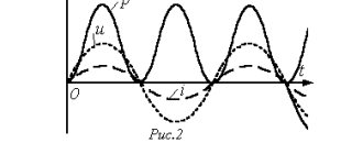
Since in this case there is not only a process of converting electricity into some other (light, heat, etc.), but also a process of oscillation of the electric and magnetic field, a phase shift appears between the current and voltage, and this should be taken into account in further calculations.
When calculating power in an alternating current circuit, it is customary to distinguish active, reactive and apparent components.
Concept of active power
Active “useful” power is that part of the power that directly characterizes the process of converting electrical energy into some other energy. It is designated by the Latin letter P and measured in watts (W).
Calculated using the formula: P = U⋅I⋅cosφ,
where U and I are the root mean square value of the voltage and current of the circuit, respectively, cos φ is the cosine of the phase shift angle between voltage and current.
IMPORTANT! The formula described earlier is suitable for calculating circuits with a voltage of 220V, however, powerful units usually use a network with a voltage of 380V. In this case, the expression should be multiplied by the root of three or 1.73
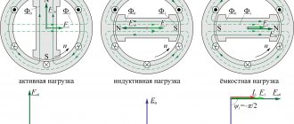
Inductive element L
An inductive element (let's take an inductor as an example) consists of turns of wire insulated with each other. When current flows, the coil becomes magnetized. If you change the polarity of the source, the coil will begin to release the stored energy back, trying to maintain the amount of current in the circuit. Therefore, when a variable component flows through it, the energy accumulated during the passage of the positive half-cycle will not have time to dissipate and will prevent the passage of the negative half-cycle. As a result, the negative half-cycle will have to extinguish the energy stored by the coil. As a result, voltage (U) will lead current (I) by some angle φ. Below is the result of simulating operation on a LR load L=1*10-3 H, R=0.5 Ohm. Uist= 250 V, frequency f=50 Hz.
Figure 1. Source operation on RL load
φ is the phase difference between U and I.
Reactance is designated by the letter X, total Z, active R.
For inductance:
Where ω – cyclic frequency
— supply voltage frequency, Hz;
L – coil inductance;
Conclusion: the higher the inductance L or frequency, the greater the coil's resistance to alternating current.
What does this mean
In alternating current networks, which absolutely the whole world uses today, there is no way to do without active and reactive powers - they are interdependent and even necessary. Active electricity refers to the voltage that is generated at thermal power plants, state district power plants, nuclear power plants, a mobile generator standing in a garage, etc. – it goes to the consumer (to factories, factories, to our home) and powers all electrical appliances from a network of ≈220-380 V. At the same time, the function of the reactive component of the total current is to wander aimlessly from the source to the consumer and back. So where does this seemingly useless substance come from?
The thing is that in our homes, businesses and any other electrified objects there are devices with inductive coils (for example, we can take the stator of a motor), where magnetic fields constantly arise. That is, some of them rotate the rotor (armature), and some return back, and so on ad infinitum, as long as there is movement of active energy. This is well demonstrated by a mug of fresh beer: a person drinks only a small part of the foam with the liquid, and leaves the rest in the glass or blows it to the ground. But this very foam is a product of fermentation (induction), without which there will be no beer at all.
Now we can sum up the first conclusion in understanding the topic: if there is an inductive load (and it always exists), then a reactive current will certainly appear, consumed by induction, which itself creates it. That is, induction generates reactive power, then consumes it, generates it again, and so on constantly, but therein lies one problem. To move the reactive substance back and forth, active energy is needed, which is consumed due to the constant movement of electrons along the wires (heating of the wires).
It will be interesting➡ PNP transistor
Can we come to the conclusion that the active power of a generator is the complete opposite of reactive, seemingly useless power? But that's not true. Remember, the sisters are inseparable from each other, because they love each other, and no one will drink beer without foam, and the drink will not be able to ferment without it. The same can be said about reactive power - without it it is impossible to create magnetic fields, so this force will have to be taken into account. But then the brain convolutions of the inventors came into play, who decided to reduce the territorial space (not to drive back and forth along the wires) of this not entirely clear substance and produce it in close proximity to the object of consumption.
For a clear example, you can take the well-known electric hair dryer, which has a motor that rotates a shaft with blades - it is called a turbine for supplying hot air. So, in order to relieve the power line from the useless running of the reagent from the station to the consumer and back, a capacitor of the required capacity is built into the device body. Imagine the same electric welding or turning shop with dozens of powerful machines - what potential is released by reactive current to increase efficiency. In technical terms, the installation of capacitors or other static compensating elements is called reactive power compensation. It turns out that active and reactive power are two inextricably linked quantities.
Generators at power plants of any type can also generate reactive power. To do this, it is enough to change the excitation current (overexcitation, underexcitation) and the generator will be both a supplier and a consumer of this value. But these are just the laws of physics, which in this case are not very beneficial for people, so it is best to transfer the storage and release capacity as close to the source as possible - to the body of the device (unit) or to the production workshop.
Reactive electricity metering for enterprises
Another thing is enterprises and organizations. A huge number of electrical equipment are installed in production facilities and industrial workshops, and the total supplied electricity contains a significant portion of reactive energy, which is necessary for the operation of power supplies and electric motors. Active and reactive electricity supplied to enterprises and organizations requires a clear separation and a different method of payment for it. In this case, the basis for regulating relations between the electricity supply company and end consumers is a standard contract. According to the rules established in this document, organizations that consume electricity above 63 A need a special device that provides reactive energy readings for accounting and payment. The network company installs a reactive electricity meter and charges according to its readings.
How to find out what power is in an AC circuit
It is worth pointing out that this is a value that is directly related to other indicators. For example, it is directly dependent on time, force, speed, vector of force and speed, modulus of force and speed, moment of force and speed of rotation. Often in formulas when calculating electrical power, the number Pi is also used with the resistance indicator, instantaneous current, voltage in a specific section of the electrical network, active, total and reactive power. Direct participants in the calculation are the amplitude, angular velocity and initial current strength with voltage.
Power formula in an alternating current circuit
Transformer operating modes
The most economical operation of a transformer in terms of annual costs and losses will be in the case when it operates with an overload during peak hours (operation tends to operate in modes where during peak load hours of a given transformer it does not exceed its rated power). In real conditions, the value of the permissible load is selected in accordance with the load curve and the initial load factor and also depends on the ambient temperature at which the transformer operates.
The load factor, or the fill factor of the daily load schedule, is almost always less than one:
Depending on the nature of the daily load schedule (initial load factor and maximum duration), the equivalent ambient temperature, the time constant of the transformer and the type of its cooling, according to GOST, systematic overloads of transformers are allowed.
In a single-phase circuit
You can understand what power indicator is in a single-phase alternating current circuit by using a current transformer. To do this, you need to use a wattmeter, which is connected through a current transformer. The readings should be multiplied by the transformer current coefficient. When measuring power at high voltage, a current transformer is needed to insulate the wattmeter and ensure the safety of the user. The parallel circuit is not connected directly, but thanks to a voltage transformer. Secondary windings with housings of measuring transformer installations must be grounded to avoid accidental insulation damage and high voltage contact with devices.
Note! To determine the parameters in the network, it is necessary to multiply the ammeter by the transformer current coefficient, and multiply the numbers obtained by the voltmeter by the transformer voltage coefficient.
In a single-phase circuit
Practical application and correction
If a load with a current leading or lagging behind the voltage by some angular value is connected to a socket with a sinusoidal voltage of 50 Hz and 230 V, then increased power will be generated on the active internal coil. This means that when operating under such conditions, a lot of heat is generated, and the power plant removes it in an increased amount compared to the use of a resistive load.
Efficiency and power coefficients differ from each other. The power indicator does not affect the consumption of the receiver connected to the network, but it changes the energy losses in the underwater wires and places where energy is generated or converted. In the house, the electric meter does not respond to the manifestation of power, since only the energy that powers the appliances is paid for.
Efficiency affects the consumed active load. For example, an energy-saving lamp consumes one and a half times more electricity than a similar incandescent device. This indicates a high efficiency of the first lamp. But the load indicator can be low and high in both options.
The correction consists of bringing the consumption of a device with a low power factor to standard values when powered from an AC power circuit. Technically, this is accomplished by using an effective circuit on the input device, which helps to evenly use the phase power and eliminates overload of the neutral wire. At the same time, surges in consumer current at the top of the supply voltage sinusoid are reduced.
The reactive load is adjusted when a reverse-acting element is included in the main line. For example, in an AC motor, a capacitor is placed parallel to the supply line to compensate for the action. An active or passive corrector system is used when the used current changes during the oscillatory period of the supply voltage to convert the coefficient. A simple example is a series connection of a choke. In this case, the end devices consume current disproportionately to harmonic distortion. The coil smooths out the wave impulses.
Electrical appliances affecting the quality of consumption
The power factor is equal to unity when connecting lamps and heaters. It decreases to 0.7 or less when electric motors and other components with reactive components, which dominate in energy consumption, are added to the circuit.
The correct application of power definitions and calculations helps optimize the electrical network design taking into account the characteristics of the connected loads. The above information will be useful at the stage of determining the parameters of wiring and circuit breakers. The integrated use of this knowledge will increase the reliability of power supply and prevent the occurrence and development of emergency situations.
Nonlinear load
It has the peculiarity that voltage and current are not proportional. Nonlinear loads include televisions, stereos, electronic desktop clocks, computers and its components. The nonlinearity itself is due to the fact that this electronic device uses switching power supplies. To recharge the capacitors in the switching power supply, the top of a sine wave is sufficient.
The rest of the time, the capacitor does not consume energy from the network. In this case, the current has a pulse quality. What does this all lead to? This causes the sine wave to become distorted. But not all electronic devices work with a distorted sine wave. This problem is solved through the use of double conversion stabilizers, where mains power is converted to constant power. Then it is converted from a constant into a variable of the desired shape and amplitude.
What is the difference between active power and reactive power – All about electricity
The power characteristics of an installation or network are basic for most known electrical appliances. Active power (transmitted, consumed) characterizes the part of the total power that is transmitted over a certain period of alternating current frequency.
Only alternating current can have active and reactive power, since the network characteristics (current and voltage) of direct current are always equal.
The unit of measurement for active power is Watt, while reactive power is measured by reactive voltampere and kiloVAR (kVAR).
It is worth noting that both full and active characteristics can be measured in kW and kVA, this depends on the parameters of the specific device and network. In industrial circuits it is most often measured in kilowatts.
Energy ratio
Electrical engineering uses the active component to measure the energy transfer of individual electrical devices. Let's look at how much power some of them consume:
| Device | Power of household appliances, W/hour |
| Charger | 2 |
| Fluorescent lamp DRL | From 50 |
| Acoustic system | 30 |
| Electric kettle | 1500 |
| Washing machine | 2500 |
| Semi-automatic inverter | 3500 |
| High pressure washer | 3500 |
Based on everything said above, active power is a positive characteristic of a specific electrical circuit, which is one of the main parameters for selecting electrical appliances and controlling electricity consumption.
Active component generation
Reactive component designation:
This is a nominal value that characterizes the loads in electrical devices using EMF fluctuations and losses during operation of the device. In other words, the transmitted energy goes to a specific reactive converter (this is a capacitor, diode bridge, etc.) and is manifested only if the system includes this component.
To find out the active power indicator, you need to know the total power; the following formula is used to calculate it:
It will be interesting➡ Design and principle of operation of alternating current generators
S = UI, where U is the network voltage and I is the network current.
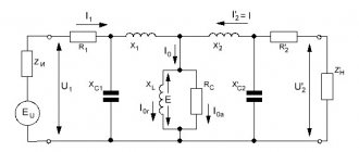
The same calculation is performed when calculating the energy transfer level of the coil with a symmetrical connection. The diagram looks like this:
Symmetrical load diagram
The calculation of active power takes into account the phase angle or coefficient (cos φ), then:
S = U * I * cos φ.
A very important factor is that this electrical quantity can be either positive or negative. It depends on what characteristics cos φ has.
If the phase shift angle of a sinusoidal current is in the range from 0 to 90 degrees, then the active power is positive, if from 0 to -90, then it is negative.
The rule is valid only for synchronous (sinusoidal) current (used to operate an asynchronous motor or machine tool equipment).
Also, one of the characteristic features of this characteristic is that in a three-phase circuit (for example, a transformer or generator), the active indicator is completely generated at the output.
Three-phase network calculation
Maximum and active power is denoted by P, reactive power by Q.
Due to the fact that reactive is determined by the movement and energy of the magnetic field, its formula (taking into account the phase shift angle) has the following form:
QL = ULI = I2xL
For non-sinusoidal current it is very difficult to select standard network parameters. To determine the required characteristics for the purpose of calculating active and reactive power, various measuring devices are used. This is a voltmeter, ammeter and others. Based on the load level, the desired formula is selected.
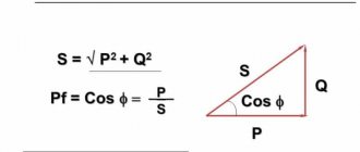
Due to the fact that the reactive and active characteristics are related to the total power, their relationship (balance) is as follows:
S = √P2 + Q2, and all this equals U*I.
But if the current passes directly through the reactance. There are no losses in the network. This is determined by the inductive inductive component - C and resistance - L. These indicators are calculated using the formulas:
Inductance resistance: xL = ωL = 2πfL,
Capacitance resistance: xc = 1/(ωC) = 1/(2πfC).
To determine the ratio of active and reactive power, a special coefficient is used. This is a very important parameter by which you can determine what part of the energy is used for other purposes or is “lost” during operation of the device.
If there is an active reactive component in the network, the power factor must be calculated.
This quantity has no units of measurement; it characterizes a specific current consumer if the electrical system contains reactive elements.
Using this indicator, it becomes clear in which direction and how the energy shifts relative to the network voltage. To do this you will need a voltage triangle diagram:
Stress Triangle Diagram
For example, if there is a capacitor, the coefficient formula is as follows:
cos φ = r/z = P/S
To obtain the most accurate results, it is recommended not to round the data obtained.
Considering that when the currents resonate, the reactive power is 0:
Q = QL – QC = ULI – UCI
In order to improve the quality of operation of a particular device, special devices are used to minimize the impact of losses on the network. In particular, this is a UPS. This device does not require electrical consumers with a built-in battery (for example, laptops or portable devices), but for most others an uninterruptible power supply is necessary.
When installing such a source, you can not only determine the negative consequences of losses, but also reduce the cost of paying for electricity. Experts have proven that on average, a UPS will help save from 20% to 50%. Why is this happening:
- The load on power transformers is significantly reduced;
- The wires heat up less, this not only has a positive effect on their operation, but also increases safety;
- Signaling and radio devices have reduced interference;
- Harmonics in the electrical network are reduced by an order of magnitude.
Overloads of power transformers
Overloads are determined by converting a given load curve into a thermally equivalent one (Fig. 3.5). The permissible load of the transformer depends on the initial load, the maximum load and its duration and is characterized by the load excess factor:
Permissible systematic overloads of transformers are determined from graphs of the load capacity of transformers, specified in tables or graphically. The overload factor is transmitted depending on the average annual air temperature/sp type of cooling and transformer power, the initial load factor kn n and the duration of the two-hour equivalent maximum load tmax.
For other values of tmax, the permissible value can be determined from the load capacity curves of the transformer.
If the maximum load schedule in summer is less than the rated power of the transformer, then in winter a long-term 1% overload of the transformer is allowed for each percentage of underload in summer, but not more than 15% . The total systematic overload of the transformer should not exceed 150%. In the absence of systematic overloads, long-term loading of transformers with a current 5% higher than the rated current is allowed, provided that the voltage of each winding does not exceed the rated one.
On transformers, it is allowed to increase the voltage above the rated one: for a long time - by 5% at a load not higher than the rated one and by 10% at a load not higher than 0.25 rated; short-term (up to 6 hours per day) - by 10% at a load not higher than the nominal one.
Additional overloads of one branch due to prolonged underload of the other are allowed in accordance with the instructions of the manufacturer. Thus, three-phase transformers with a split winding of 110 kV with a power of 20, 40 and 63 MVA allow the following relative loads: with a load of one branch of the winding 1.2; 1.07; 1.05 and 1.03 loads of the other branch should be 0, respectively; 0.7; 0.8 and 0.9.
Read also: Tool alloy steels marking