The main factors causing ferroresonance phenomena in electrical networks are capacitive and inductive elements that can form oscillatory circuits during switching moments. This effect is especially noticeable in power transformers, linear boost transformers, voltage transformers, shunt circuits and similar equipment equipped with massive windings.
Ferroresonance phenomena in electrical networks
The main factors that give rise to ferroresonance phenomena in electrical networks are elements of capacitive and inductive types.
They are capable of forming oscillatory circuits during switching periods. This effect is especially noticeable in power type transformers, linear booster transformers, shunt circuits and similar devices that are equipped with massive windings. This phenomenon comes in two types: resonance of currents and voltage.
Voltage ferroresonance is possible when there is inductance in the network, characterized by a nonlinear current-voltage property. This characteristic is characteristic of inductors, where the cores are made from ferromagnetic components. This is especially true for rectifiers from the NKF line. This negative phenomenon is caused by a small indicator of resistance of ohmic and inductive types in relation to power transformers.
Preparation of equipment for conducting experiments with nonlinear ferromagnets
It should be noted that the ability to design and calculate devices based on the use of the ferroresonance phenomenon can be considered aerobatics. The reason for this is the little-known nonlinear processes occurring in coils with a ferromagnetic core, which an untrained person cannot not only predict, but even assume the very possibility of the existence of nonlinearity.
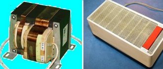
To film experiments with nonlinear processes and the phenomenon of ferroresonance, I decided to assemble a transformer specifically for this purpose. It will be used for a whole series of experiments with nonlinear processes.
When preparing the transformer, special attention had to be paid to the electrical insulation of the steel plates from each other in order to minimize the energy spent not only on reversing the magnetization of the transformer core, but also on reaching its saturation threshold.
The cross-section of the transformer rods is 50x52 mm. The height of the rods (counting from the partition) is 145 mm.
Let's watch short video clip No. 1:
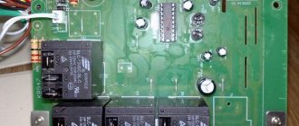
For some experiments, I specially made the left (in the photo) winding with Litz wire. A photo of this winding is shown in the illustration below. The Litz wire is made of 7 copper wires twisted together in varnish insulation. The diameter of each is 0.7 mm, and the cross-sectional area of the litzendarate is about 16 mm2. The total length of the Litz wire was about 50 meters, which was enough for 160 turns of winding.
The right (pictured) winding of the transformer remains factory-made.
The transformer is assembled in such a way that it can be easily disassembled, remove the top plate pack, and quickly remove and add spacers between the two plate packs.
The weight of the assembled transformer is more than 15 kilograms.
Ferroresonance in a voltage transformer
When a voltage transformer is connected to the network, series-combined LC circuits are formed in it, which are a resonant-type circuit. When an inductive element with a nonlinear current-voltage property is connected in series to a capacitive-type element, the voltage in this zone of the circuit is characterized as active-inductive.
After a certain time period, the voltage value on the inductive element becomes peak, the magnetic circuit is energized, and the voltage on the capacitive type component continues to increase. Ferroresonance in a voltage transformer occurs when the voltage of the inductance and capacitive element becomes equal.
The rapid transition of the applied voltage from the active-inductive type to the active-capacitive type is referred to as “phase reversal”. This effect is dangerous for electrical appliances.
What are nonlinear processes?
Let's remember what the formulas for calculating the capacitance of capacitors and the inductance of coils look like.
As you can see, the formulas contain two parameters ε
μ
, which characterize the parameters of dielectric and magnetic materials present in concentrated or distributed
capacitive
and
inductive
elements.
If you change the geometric parameters, for example, by changing the area of the capacitor plates, the distance between the plates C
or the length of the inductor
L
, which are part of the oscillatory circuits, then we will be able to observe the occurrence of
parametric resonance
. The very reason for the occurrence of this resonance was clarified and clearly presented in my videos about the operation of capacitors and inductors. In this work we will not deal with parametric resonance.
Typically, when we calculate devices based on inductors and capacitors, we assume that the parameters ε
and
μ
are constant in the calculations.
But actually it is not. The parameters of the environment, dielectric ( ε
) and magnetic (
μ
) materials depend on the strength of the electric
E
and magnetic
H
, although to varying degrees, so it would be correct to rewrite the formulas differently:
Now let us recall the formulas that take into account the dependence of energy
capacitor
WC
from the value of its capacitance (
C
), as well as
the energy
of the coil
WL
from its inductance (
L
):
1) for a capacitor, the energy linearly depends on the value of C
;
2) for an inductor, the energy depends linearly on the value of L.
Therefore, based on the dependence ε
(
E
) and
μ
(
H
) it would be correct to write
C
(
E
) and
L
(
H
).
value
will additionally depend on the electric field strength E
, and the inductance value will depend on the magnetic field strength
H. Based on this, the dependence of the energy W C
on
C
and
W L
on
L
will also be nonlinear. Thus, the reason for the nonlinearity of the capacitor capacitance is the nonlinear response to the electric field of the dielectric material of the capacitive circuit element (capacitor).
Our industry produces mainly capacitors in which the dependence of capacitance on the applied voltage is very insignificant. Today it is difficult to find capacitors that use ferroelectrics as a dielectric, due to which their capacitance strongly depends on the applied voltage. In Soviet times, such capacitors were produced by industry, which were called varicondas. Nonlinear capacitive elements are mentioned here only for the sake of completeness. In this work we will deal only with nonlinear inductive elements
.
Due to nonlinearity
inductance is
the nonlinear response
of the magnetic circuit material
to the magnetic field
of the inductive element
.
To illustrate this, let us consider the dependence of the magnetic permeability
μ
of ferromaterials on the magnetic field strength
H
, and for different materials their graph looks like this:
Magnetic permeability of different materials:
1– permalloy
; 2 –
pure iron
.
The graph shows that at a magnetic field strength of about 3-4 A/m, the reaction of permalloy to minor changes in field strength is colossal. Its magnetic permeability μ
varies from tens of units to tens of thousands!
in μ occurs differently
at iron. As the magnetic field strength increases from units of A/m to 30 A/m, the magnetic permeability of iron becomes maximum, and with a further increase it begins to decrease again. Therefore, the magnitude of the inductance of a coil wound on an iron core strongly depends on the strength of the magnetic field created by the coil itself, that is, on the magnitude of the current in it.
Ferroresonant stabilizers
Ferroresonance stabilizer
Ferroresonance rectifiers are not equipped with a built-in voltmeter, making it difficult to measure the output voltage of the network. You won't be able to adjust the voltage yourself. Ferroresonance type stabilizers partially distort real readings, the error is up to 12%.
Those who use such devices for a long time must remember that they are capable of emitting a magnetic field, which can disrupt the proper functioning of household electrical appliances. Stabilizers of this class are configured at the factory; they do not require any additional settings at home.
Consequences and combating resonant phenomena
On power transformers with an operating voltage of 220 kV, as a result of resonance, the voltage can increase abruptly to 300 kV, and the current instantly rises to such a force that the windings are destroyed as a result of thermal effects (electrodynamic shock).
To prevent such phenomena from occurring, special operations are usually planned in switching programs that exclude the occurrence of resonance processes, and elements are often specially installed in the bus system, the resistance of which is designed to combat the phenomenon of resonance.
The influence of the stabilizer on technology
A ferroresonant voltage stabilizer, the operating principle of which is not simple, affects household appliances as follows:
- Radio receiver - signal reception sensitivity can be reduced, the output power indicator is significantly reduced.
- Music center - the output power of such equipment can be significantly reduced, erasing and recording new discs is significantly worse.
- TV – when connected to a stabilizer, you can observe a significant decrease in the quality of the picture on TV, some colors are not transmitted correctly.
The electrical circuit of modern ferroresonant type normalizers has been improved, which allows them to withstand heavy loads. Such devices can guarantee precise regulation of the mains voltage. The adjustment procedure is performed by a transformer.
Operating modes
The operating modes of stabilizers depend on a number of factors. The power indicator and the class of the device have a direct impact. The power characteristics of the device may be different; they must be selected taking into account the type of electrical equipment being connected.
The operating modes of the rectifier depend on the following types of load:
- inductive;
- active;
- capacitive
Active loading in its pure form is extremely rare. It is necessary only in those circuits where the variable value of the device has no restrictions. Capacitive loads can only be used for those rectifiers that have low power.
Switching of idle buses
500 kV circuit breakers are multi-break. Modern circuit breakers usually have two breaks, both air and gas-insulated (including foreign ones, for example, from ABB). To distribute the voltage evenly across the breaks, special capacitors (voltage dividers) are connected parallel to them. After the switch is turned off, the disconnected object (bus system) remains connected to the voltage source through the equivalent capacitance of the break dividers.
To completely disconnect the connection, switching of the disconnector is required. The capacitance of the capacitors that shunt the breaks of the switches, together with the capacitance of the busbar and the equipment connected to it to the ground, form a ferroresonant circuit.
In 110-220 kV networks, the number of simultaneously switched off switches when switching a busbar can be very large.
At a 500 kV substation there are usually significantly fewer connections; in addition, outdoor switchgear-500 are usually designed according to 3/2 or 4/3 schemes. The diagram of the ORU-500, made according to the 3/2 scheme, is shown in Fig. 3, a. The voltage transformer is installed on section SSh1. When this section is disconnected, two 500 kV circuit breakers are switched off in parallel. The capacitances of the dividers in 500 kV circuit breakers vary over a fairly wide range depending on the type of circuit breaker.
The smallest capacitance for VNV type switches is 330 pF, the largest for VV type switches is 550 pF.
Thus, the total equivalent capacitance of the switch dividers in the circuit in Fig. 3, and can be 660-1100 pF. The total capacitance to ground can be estimated as the capacitance of the VT (125 pF), the capacitance of all disconnectors (2 x 200 pF), switches (2 x 125 pF) and busbar (10 pF/m ~ 300 pF), that is, 1075 pF. The calculation diagram for studying processes when the idle busbar is disconnected is shown in Fig. 3, b. The results of modeling the shutdown of the idle busbar in a circuit with TN types NKF-500 and NAMI-500 are shown in Fig. 4. and fig. 5, respectively.
Divider and busbar capacitances: C1 = 1100 pF, C2 = 1075 pF, source voltage 500/v–3 kV, the switch is turned off at the moment of maximum voltage on the VT (0.1 s from the beginning of the calculation).
From the computer oscillograms it is clear that in this case a stable ferroresonance occurs in the NKF type VT, with an effective current of 0.73 A. In this mode, the VT will quickly fail .
In operation, there is a known case of damage to a TN type NKF500 in 1973 at the Kostroma State District Power Plant, and the ratio of the capacitances of the busbar and switches was: 1.1/1.015 nF. In NAMI type VTs, a stable process also occurs, but at the 1/3 subharmonic and with a significantly lower effective current. The possibility of ferroresonance occurring in the circuit in Fig. 3, b (when the idle busbar is turned off) depends on two main factors: the source voltage and the value and ratio of the capacitances of the dividers and the busbar.
By performing numerous calculations while varying these capacitances (the voltage is equal to the nominal voltage), it is possible to obtain the regions of existence of ferroresonance (regions of dangerous parameters). These areas for TN NKF-500 and NAMI-500 are shown in Fig. 6 (source voltage 525/v–3 kV).
From this figure it can be seen that in the NKF, with the total capacitance of the dividers more than 1 nF (switching off two or more switches), ferroresonance at the main or subharmonic 1/3 occurs at almost any busbar capacitance. Ferroresonance at the fundamental harmonic is accompanied by significant overvoltages (up to 3.0 Uph.max). Switching the idle busbar with a NAMI type voltage transformer at a certain capacitance ratio also leads to the appearance of a ferroresonance mode.
A characteristic feature is that a stable process occurs only at the 1/3 subharmonic. The currents arising in this case are relatively small, for example, even with large capacitances C1 = C2 = 4 nF, IВН.ТН.eff = 0.32 A.
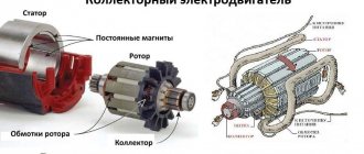
Operating principle of ferroresonance stabilizers
The primary winding, which receives the input voltage, is located on the magnetic core. It has a large cross-section, which allows the core to be kept in an unsaturated state. At the input voltage forms magnetic fluxes.
The output voltage is generated at the terminals of the secondary winding. A load is connected to this winding, which is located on the core, has a small cross-section and is in a saturated state. In case of anomalies in the mains voltage and magnetic flux, its value is not actually modified, and the EMF indicator also remains unchanged. During an increase in the magnetic flux, some of it will be closed on the magnetic shunt.
The magnetic flux takes on a sinusoidal shape and, as it approaches the amplitude indicator, a separate section of it goes into saturation mode. The increase in magnetic flux stops. The flow through the magnetic shunt will be closed only when the magnetic flux is equal to the amplitude.
The presence of a capacitor allows the ferroresonant stabilizer to operate with an increased power coefficient. The stabilization indicator depends on the level of slope of the horizontal curve with respect to the abscissa. The slope of this area is significant, so it is impossible to achieve a high level of stabilization without auxiliary equipment.
Introduction.
I thank everyone who has kindly and financially supported my educational project.
I will also have to say a few words to my ill-wishers. If someone is not satisfied with my activities on this channel, then instead of “reforging” me, convincing me to think the same way as you, then it’s better than wasting your time, leave this channel and look for something for yourself on the vast expanses of the Internet. something more interesting.
A few more words about the behavior of guests and visitors to the channel. Most often, comments are written by those who were accidentally brought to the channel or attracted by the title of some work, or simply looked in out of curiosity. Having watched the very first video on the channel, without reading the texts to my videos, without knowing the rest of my works, they begin to write their comments, which may have been answered a long time ago in the comments given to this or another work.
Some channel visitors go even further - they reproach me for allegedly deceiving channel visitors, telling them fables, giving false information, as a result, they are supposedly very worried about this. I will not give here the nicknames and names of these visitors, but I consider their actions to be a cheap provocation, with the goal of forcing me to act in their interests, to begin to make excuses to them or to prove that I am right, launching into long explanations of what the provocateurs themselves could search and read on one's own. In the future, I will not respond to such comments, and all provocations, reproaches and insults from the comments will be removed. So if your time is valuable to you, take pity on it and don’t waste it in vain.
For everyone who visited my channel for the first time, I draw attention to the basic rules of behavior on the channel:
1) before writing a comment or asking a question, please take the trouble to read the text to a particular video, as well as the comments to the video that interests you. Perhaps there is already an answer to your question;
2) all comments that are not relevant, containing profanity, insults and reproaches from the comments will simply be deleted;
3) all constructive suggestions and substantive questions are welcome, and I will try to give a detailed answer to each of them.
4) I don’t have to prove the existence of a scalar magnetic field to anyone, I don’t have to explain anything, since it’s a personal matter for each person to accept its existence or not;
5) in some of the works exhibited on my channel, I have already cited more than once references to the works of G.V. Nikolaev and other authors, and I consider it unnecessary to cite them in each work;
6) whoever is interested in the topic of the scalar magnetic field, look for books on the Internet on your own (they are available), read, think, perform experiments, as I did in my time, and not only me;
Advantages and disadvantages
Among the key advantages of ferroresonant rectifiers are:
- resistance to overloads;
- wide range of operational values;
- speed of adjustment;
- the current takes the form of a sine;
- high leveling accuracy.
But with all these advantages, devices of this class also have their disadvantages:
- The quality of operation depends on the load indicator.
- During operation, external electromagnetic interference is generated.
- Unstable operation at low loads.
- High weight and size indicators.
- Noise occurs during operation.
Most modern models do not have such disadvantages, but they are distinguished by their considerable cost, sometimes higher than the price of a UPS. Also, the devices are not equipped with a voltmeter, which makes it impossible to adjust them.
Tips for choosing
The design of rectifiers is constantly being modernized, the quality of their circuits is improving, which allows them to withstand significant ferroresonant overvoltages. Modern models are distinguished by their high level of performance, accuracy of adjustment and long service life. The modes are set by the power characteristics of the device and its type.
The main condition for choosing a ferroresonant stabilizer is its connection location. Usually it is installed at the entrance of the electrical network to the premises or near household appliances. If a rectifier is installed for all equipment, it is necessary to select devices with a high power level and connect them immediately behind the distribution panel.
Conditions of occurrence
In normal operating modes of a three-phase network, ferroresonance is unlikely, since the capacitances of the structural elements are shunted by the inductive reactance of the input supply network.
Normal mode is symmetrical. The most common cause of ferroresonance in practice is an ungrounded (isolated) neutral in combination with an open-phase mode. With an isolated neutral, the network capacitance relative to the ground is connected in series with the windings of a power transformer or electromagnetic voltage transformer, which creates favorable conditions for ferroresonance. An incomplete phase mode can occur when there is an incomplete phase connection, when one phase is broken, or when there is an asymmetrical short circuit.
DIY ferroresonant voltage stabilizer
The ferroresonant circuit is the simplest for DIY production. Its operation is based on the magnetic resonance effect.
The design of a fairly powerful ferroresonant type rectifier can be assembled from three elements:
- primary choke;
- secondary throttle;
- capacitor.
However, the simplicity of this option is accompanied by a whole set of inconveniences. A powerful normalizer made using a ferroresonant circuit turns out to be massive, bulky and heavy.
How to “touch” ferroresonance?
The main feature of ferroresonance
is that
it
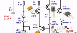
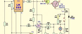
can arise in response to disturbances of various modes in the same circuit. To illustrate this statement, the diagram below has been assembled:
To conduct the experiment, we used our transformer, a laboratory autotransformer (latr) RNO-250-5 and several oil capacitors. Despite the shabby appearance on the outside, the inside of the latre looks like new.
Using capacitors, I created the conditions for the occurrence of ferroresonance
, although the capacitance of the capacitors is still small to start it.
With any minor provoking factor, the transformer can either enter or exit ferroresonance. For example, when a long winding is short-circuited, the inductance of the coil changes so that the conditions for entering resonance are improved, and when a short winding is short-circuited, ferroresonance due to high currents (low load resistance), as always, stops.
The oscillogram above clearly shows that on the winding of the transformer, which has entered ferroresonance, the voltage shape changes from the usual sinusoidal to a shape close to rectangular, which is evidence of the transformer core entering saturation.
Let's watch video fragment No. 2: