Electromotive force. Internal resistance of the current source.
Outside forces. To maintain a constant potential difference at the ends of the conductor, and therefore the current, it is necessary to have external forces of a non-electrical nature, with the help of which the separation of electrical charges occurs.
Third-party forces are any forces acting on electrically charged particles in a circuit, with the exception of electrostatic ones (i.e. Coulomb forces).
Third-party forces set in motion charged particles inside all current sources: in generators, power plants, galvanic cells, batteries, etc.
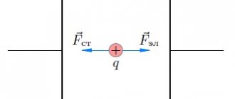
When a circuit is closed, an electric field is created in all conductors of the circuit. Inside the current source, charges move under the influence of external forces against Coulomb forces (electrons move from a positively charged electrode to a negative one), and throughout the rest of the circuit they are driven by an electric field (see figure above).
In current sources, in the process of separating charged particles, different types of energy are converted into electrical energy. Based on the type of converted energy, the following types of electromotive force are distinguished:
- electrostatic - in an electrophore machine, in which mechanical energy is converted into electrical energy by friction;
- photoelectric - in a photocell. Here the conversion of light energy into electrical energy occurs: when certain substances are illuminated, for example, selenium, copper (I) oxide, silicon, a loss of negative electrical charge is observed;
— chemical — in galvanic cells, batteries and other sources in which chemical energy is converted into electrical energy.
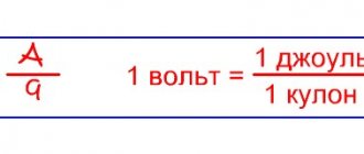
Electromotive force (EMF) is a characteristic of current sources. The concept of EMF was introduced by G. Ohm in 1827 for direct current circuits. In 1857, Kirchhoff defined EMF as the work of external forces when transferring a unit electric charge along a closed circuit:
where ɛ is the emf of the current source, Ast is the work of external forces, q is the amount of transferred charge.
Electromotive force is expressed in volts.
We can talk about electromotive force at any part of the circuit. This is the specific work of external forces (work to move a single charge) not throughout the entire circuit, but only in a given area.
Let there be a simple closed circuit consisting of a current source (for example, a galvanic cell, battery or generator) and a resistor with a resistance R. The current in the closed circuit is not interrupted anywhere, therefore, it also exists inside the current source. Any source represents some resistance to current. It is called the internal resistance of the current source and is denoted by the letter r.
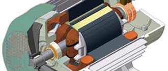
In a generator, r is the winding resistance; in a galvanic cell, it is the resistance of the electrolyte solution and electrodes.
Thus, the current source is characterized by the values of EMF and internal resistance, which determine its quality. For example, electrostatic machines have a very high EMF (up to tens of thousands of volts), but at the same time their internal resistance is enormous (up to hundreds of megohms). Therefore, they are unsuitable for generating high currents. Galvanic cells have an EMF of only approximately 1 V, but the internal resistance is also low (approximately 1 Ohm or less). This allows them to obtain currents measured in amperes.
Source
From electrostatics to electrokinetics
Between the end of the 18th and the beginning of the 19th century, the work of scientists such as Coulomb, Lagrange and Poisson laid the mathematical foundations for the determination of electrostatic quantities. Progress in the understanding of electricity at this historical stage is obvious. Franklin had already introduced the concept of “amount of electrical substance,” but so far neither he nor his successors have been able to measure it.
Following Galvani's experiments, Volta tried to find evidence that the animal's "galvanic fluids" were of the same nature as static electricity. In his search for truth, he discovered that when two electrodes of different metals come into contact through an electrolyte, both become charged and remain charged despite the circuit being closed by the load. This phenomenon did not correspond to existing ideas about electricity because electrostatic charges in such a case had to recombine.
Volta introduced a new definition of the force acting in the direction of separating charges and maintaining them in this state. He called it electromotive. Such an explanation for the description of battery operation did not fit into the theoretical foundations of physics at that time. In the Coulomb paradigm of the first third of the 19th century. d.s. Volta was determined by the ability of some bodies to generate electricity in others.
Ohm made the most important contribution to the explanation of the operation of electrical circuits. The results of a series of experiments led him to the construction of the theory of electrical conductivity. He introduced the quantity “voltage” and defined it as the potential difference across the contacts. Like Fourier, who in his theory distinguished between the amount of heat and temperature in heat transfer, Ohm created a model by analogy relating the amount of charge transferred, voltage and electrical conductivity. Ohm's law did not contradict the accumulated knowledge of electrostatic electricity.
You might be interested in: Principles and sources of free energy according to the Tesla scheme
Then, thanks to Maxwell and Faraday, explanatory models of current received a new field theory. This allowed the development of a field-related energy concept for both static potentials and electromotive force. The main dates for the evolution of the concept of EMF:
- 1800 - creation of the Voltaic galvanic battery;
- 1826 - Ohm formulates his law for a complete chain;
- 1831 - discovery of electromagnetic induction by Faraday.
Ideal current source
The ideal current source is an active element whose current does not depend on the voltage at its terminals. It is assumed that the internal resistance of an ideal current source is infinitely large , and therefore the parameters of the external electrical circuit, on which the voltage at the source terminals depends, do not affect the source current. The symbols of an ideal current source are shown in Fig. 1
The arrow in the current source or the signs “+” and “—” indicate the positive direction of the current i ( t )
or the polarity of the source, i.e. the direction of movement of positive charges.
Nowadays it is customary to denote current sources with the letter J , and the lower conventional graphic image is most often used.
Fig. 1 - Ideal current source
As the resistance of an external electrical circuit connected to an ideal
At a current source, the voltage at its terminals and, accordingly, the power developed by it increase indefinitely. Therefore, an ideal current source, like an ideal voltage source, is considered a source of infinite power.
A current source of finite power is depicted as an ideal current source with a passive element connected in parallel to its terminals, which characterizes the internal parameters of the source and
Representing a theoretical concept, a current source is used in a number of cases to calculate electrical circuits.
Some semblance of a current source can be a device consisting of a battery connected in series with an additional high resistance. Another example of a current source can be a five-electrode amplifying electron tube (pentode). Having an internal resistance incommensurably greater than the resistance of the external electrical circuit, these devices deliver a current that is almost independent of changes in the external load over a wide range, and it is in this respect that they are similar to a current source.
Source
Two-terminal network and its equivalent circuit
A two-terminal network is an electrical circuit containing two points of connection to other circuits. There are two types of electrical circuits:
- circuits containing a source of current or voltage;
- bipolar networks that are not sources.
The first are characterized by electrical parameters: current, voltage and impedance. To calculate the parameters of such two-terminal networks, real circuit elements are first replaced with ideal elements. The combination that results from such a replacement is called an equivalent circuit.
Attention! When working with complex electrical circuits, taking into account the fact that the device operates at the same frequency, it is permissible to convert serial and parallel branches to obtain a simple circuit available for calculating parameters.
The second type of two-terminal circuits can be characterized only by the value of internal resistance.
What is the internal resistance of a power supply
Any current source, be it a generator or a galvanic cell, has internal resistance. Its value characterizes the amount of energy losses that occur when current flows through the power source. For a generator, the internal resistance is determined by the resistance of the stator windings; for a battery, it is determined by the electrodes and electrolyte. It uses the same unit of measurement as the total circuit resistance - Ohm.
What is internal resistance
An electrical circuit must have a power source. Usually, when evaluating its parameters, they indicate what potential difference it provides between the terminals. If we talk about an ideal model of a power source, we can assume that it is capable of providing any power in an electrical circuit, taking into account the existing potential difference.
Real devices differ greatly in this aspect. To determine the performance of a battery, it is important to know what internal resistance is. It usually increases gradually over time and due to wear and tear. By analyzing the level and rate of how the internal resistance of the current source changes, you can decide whether to continue using the battery or whether it needs to be replaced.
This should be illustrated with an example. A 12 Volt battery is used to start the car engine. It is known that the current can reach 250 Amperes. However, if you take another battery with the same potential difference, then it is quite possible that it will not start the motor.
As an example of such a source, we can consider several galvanic cells connected in series. The difference in the two situations under consideration is determined by the presence of different internal resistance.
This parameter for a battery is the sum of several terms: the resistance of each terminal, the housing and the electrolyte used. In some current sources, additional elements included in this circuit may be taken into account.
It is important to consider that the concept of ohmic resistance is not applicable in this situation, since only passive elements are required in the circuit. When a closed circuit is created, current flows not only through it, but also inside the current source. Internal resistance determines the amount of energy loss in it.
Its presence in the circuit can be illustrated with another example. If there are 12 volts at the battery terminals, then at first glance you can easily predict what current strength will be with a load of 1 ohm. Obviously, you should expect a current of 12 Amps to pass through the circuit.
In fact, this statement is not true: the current will be slightly less - approximately 11.2 Amperes. There is no discrepancy with physics here. After all, when calculating, it is additionally necessary to take into account the resistance of the current source, due to which energy consumption occurs. It is called internal. It can be mentally imagined as a resistor connected in series with a current source.
How is internal resistance measured?
To determine the value of the characteristic under consideration, measurements are used during a direct short circuit of the terminals, which is called a short circuit. As you know, if you short-circuit the terminals of a source, a significant current will flow between them. This is often the result of carelessness and leads to burning of the insulation and melting of the wire.
During a short circuit, the circuit resistance becomes minimal. By accurately measuring the current in this situation and knowing the voltage at the terminals when there is no load, you can determine the internal resistance of the power supply. To do this you will need the following formula:
Finding the load value in this way is not always possible or practical, since a short circuit can cause a serious accident.
Therefore, other solutions to the question of how to find the internal resistance of a source are used. For example, using special measuring instruments. The original iMax B6, ToolkinRC M8, M6, M600 chargers are equipped with the function of measuring this parameter.
Comparison with potential difference
Electromotive force and potential difference in a circuit are very similar physical quantities, since both are measured in volts and are determined by the work done to move a charge. One of the main semantic differences is that e. d.s. (E) is caused by converting some energy into electrical energy, while potential difference (U) converts electrical energy into other forms. Other differences look like this:
- E transfers energy to the entire circuit. U is a measure of the energy between two points on a diagram.
- E causes U, but not vice versa.
- E is induced in electric, magnetic and gravitational fields.
- Concept e. d.s. is applicable only to the electric field, while potential difference is applicable to magnetic, gravitational and electric fields.
You may be interested in the principle of operation of electronic and mechanical time relays
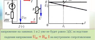
The voltage at the power supply terminals is usually different from the source emf. This occurs due to the presence of internal resistance of the source (electrolyte and electrodes, generator windings). The formula connecting the potential difference and the emf of the current source looks like U=E-Ir. In this expression:
- U is the voltage at the source terminals;
- r is the internal resistance of the source;
- I is the current in the circuit.
From this formula for electromotive force it follows that e. d.s. equal to the voltage when no current flows in the circuit. An ideal EMF source creates a potential difference regardless of the load (flowing current) and has no internal resistance.
In nature, there cannot be a source with infinite power when shorted across the terminals, just like a material with infinite conductivity. The ideal source is used as an abstract mathematical model.
Why do you need to know internal resistance?
At first glance, it may seem that the presence of internal resistance is interesting only from a theoretical point of view. In fact, in some situations, knowing what it equals can be vital.
One such situation is determining the health of a car battery. Its internal resistance is not constant. It changes under the influence of various factors and affects the voltage at the terminals. To be confident in the performance of the equipment, you need not only to be able to find its internal resistance, but also to know what its value corresponds to the norm.
The internal resistance of the power supply can be influenced by the following factors:
The influence of a large number of factors leads to the fact that different values of internal resistance can be considered normal. However, its standard increase per year is considered to be 5%. If this norm is exceeded, it means that you need to pay special attention to the health of the battery.
When analyzing, it is worth taking into account not only those values that are indicated in the technical documentation. It is also necessary to take into account how intensively the resistance changes over time. This will give more accurate information about the health of the battery and help you understand what needs to be achieved to ensure the functionality of the equipment.
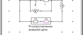
One of the simplest ways to measure internal resistance can be demonstrated with the following example. Its use is possible provided that the emf of the battery is known.
EMF (ℰ, unit of measurement - volts, V) is the electromotive force of the power source, equal to the ratio of the work of external forces to move a charge from the negative pole of the source to the positive pole to the value of this charge: ℰ = A/q. If there is no load connected to the power source, then the EMF is equal in value to the voltage at its terminals.
The situation will be considered when the EMF is 1.5 V. An electrical circuit is created in which the battery outputs are connected to a light bulb. The voltage drop across it and the current passing through the circuit are measured. They are respectively equal to 1.2 V and 0.3 A.
The figures given here are approximate. When measuring, the technician can select a different type of electrical load if he deems it necessary.
Using Ohm's law, you can determine the resistance of a light bulb:
R = U / I = 1.2 / 0.3 = 4 ohms.
In this formula, the letter R denotes the total resistance of the circuit. It can be expressed as the sum of r + R, where r is the internal resistance and R is the normal resistance.
From this formula, r = ℰ / I − R = 1.5 / 0.3 − 4 = 1 Ohm is determined.
An important condition for finding the value of r is knowledge of the magnitude of the electromotive force. This characteristic has a maximum value for new and well-charged batteries. Those that have been in use for a long time may have a significantly lower EMF due to discharge and wear, which is often associated with irreversible chemical processes in the battery.
To determine ℰ, you must disconnect any load from the power supply terminals and connect a voltmeter or multimeter in voltage measurement mode. The device will show the EMF value. Why is easy to understand. According to Ohm's law for a complete circuit:
since the voltmeter has a resistance R→∞, then the current I≈0. Therefore, the voltage at the terminals is equal to the emf:
It should also be mentioned that only an ideal voltage generator has zero internal resistance “r”. There are also elements with high internal resistance - these are different sensors, signal sources, and only an ideal current source has r=∞. In addition, there are two-terminal networks with a negative r value; it can be obtained in feedback circuits and in elements with negative differential resistance. The calculations are applicable not only for a battery, but also for any other current source, for example, a galvanic battery, a two-terminal network, a phase-zero loop. This knowledge can be used to match source and load, reduce high voltages and minimize noise.
Add a link to a discussion of the article on the forum
RadioKot >Training >Analog technology >Basics of electronics >
| Article tags: | Add a tag |
EMF and voltage. Internal resistance of power supplies.
Author: GINA Published 10/26/2005
A small addition to the conversation about batteries and accumulators, as well as Ohm’s law. Sent by GINA.
Educational program is such an educational program! Despite the fact that many of the visitors to this site are advanced radio cats and are already successfully engaged in programming and design, there are still some kittens who sometimes have questions related to the basics of radio (or even electrical) technology.
So, let's get back to the basics... According to the basics, I'm taking everyone! Oh! This is from another opera...
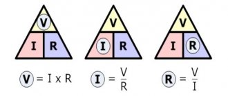
Ohm's law. That's what I mean.
We have already talked about Ohm's law. Let's talk again - from a slightly different angle. Without going into physical details and speaking in simple cat language, Ohm's law states: the greater the emf. (electromotive force), the greater the current, the greater the resistance, the less the current.
Translating this spell into the language of dry formulas we get:
I=E/R
where: I - current strength, E - E.M.F. — electromotive force R — resistance
Current is measured in amperes, emf. - in volts, and the resistance bears the proud name of Comrade Ohm. E.m.f. - this is a characteristic of an ideal generator, the internal resistance of which is considered to be infinitesimal. In real life, this rarely happens, so Ohm’s law for a series circuit (more familiar to us) comes into force:
I=U/R
where: U is the source voltage directly at its terminals.
Let's look at a simple example.
Let's imagine an ordinary battery in the form of an emf source. and a certain resistor connected in series with it, which will represent the internal resistance of the battery. Let's connect a voltmeter in parallel to the battery. Its input resistance is significantly greater than the internal resistance of the battery, but not infinitely large - that is, current will flow through it. The voltage value that the voltmeter shows will be less than the emf value. just by the amount of voltage drop across the internal imaginary resistor at a given current. But, nevertheless, it is this value that is taken as the battery voltage.
The final stress formula will have the following form:
U(baht)=EU(internal)
Since the internal resistance of all batteries increases over time, the voltage drop across the internal resistance also increases. In this case, the voltage at the battery terminals decreases. Meow!
Got it figured out!
What happens if you connect an ammeter to a battery instead of a voltmeter? Since the ammeter's internal resistance tends to zero, we will actually be measuring the current flowing through the internal resistance of the battery. Since the internal resistance of the source is very small, the current measured in this case can reach several amperes.
However, it should be noted that the internal resistance of the source is the same element of the circuit as all the others. Therefore, as the load current increases, the voltage drop across the internal resistance will also increase, which leads to a decrease in the voltage across the load. Or, as we radio cats like to put it, a voltage drop.
In order for load changes to have as little effect on the output voltage of the source as possible, they try to minimize its internal resistance.
You can select the elements of a series circuit in such a way that at any of them you get a voltage that is reduced, compared to the original, by as many times as you like.
The simplest voltage divider consists of two resistors. The smaller part of the original voltage we want to receive and transfer to the load, the lower the resistance of the resistor from which it is removed should be. In addition, the resistance of this resistor must be significantly less than the load resistance, otherwise connecting the load will change the resistance of the entire section, and the voltage across it will change.
Often, instead of one of the divider resistors, the load itself is used. In this case, the second resistor, which absorbs the excess voltage, is called a damping resistance.
By connecting a resistor in parallel with the load, you can reduce the current flowing through it. The resistor, which is turned on to branch off the excess current, is called a shunt by decent cats (SHUNT translated into Russian means a workaround).
Normal heroes always go bypass! (Joke!)
The lower the shunt resistance, the more current will flow through it and the less through the load. Ugh! I'm tired of writing such volumes on my PDA... Do you have any questions? If there are, write. Maybe I’ll remember something else from the school curriculum.
<<—Let’s remember what we’ve covered—Let’s move on—>>
| What do you think of this article? | Did this device work for you? | |
| 73 | 11 | 17 |
| 9 | 14 |
Ideal EMF source
Let's remember what EMF is. EMF is something that creates an electric current. If we connect any load to such a voltage source (even a billion halogen lamps connected in parallel), it will still produce the same voltage as it would have produced if we had not connected any load at all.
In short, no matter how much current passes through the resistor circuit, the voltage at the ends of the EMF source will always be the same. Such an EMF source is called an ideal EMF source .
But as you know, nothing is ideal in our world. That is, if our battery had an ideal source of EMF, then the voltage at the battery terminals would never sag. But it sags, and the more, the more current the load consumes. Something is wrong here. But why does this happen?
Internal resistance of the EMF source
The thing is that a resistance is “hidden” in the battery, which, relatively speaking, clings in series with the source of the battery’s emf. It is called internal resistance or output resistance. Indicated by a small letter “ r ”.
It all looks like this in the battery:
So, what do we get in its pure form?
A light bulb is a load that has resistance. So, we simplify the diagram even more and get:
We have an ideal EMF source, internal resistance r and load resistance R. Recall the article voltage divider. It says that the voltage of the EMF source is equal to the sum of the voltage drops across each resistance.
Now let's remember the article current divider. The current flowing through series-connected resistances is the same everywhere.
Let's remember algebra for 5th grade and write down everything that we just talked about. From Ohm's law for a section of the chain we obtain that
Voltage regulator.
Other names:
— voltage source;
— voltage generator;
— reference voltage source (in circuits it is usually designated as ION).
Basic requirement:
Uout. = const.
Load current
connected to the output of the voltage stabilizer
changes
depending on the value of Rload.
The ideal operating mode of the voltage stabilizer corresponds to Rload. = infinity.
Ideal voltage generator
creates
stable voltage In this case, its internal resistance is zero (Ru = 0). The load current is determined by the formula:
Iload = U / Rload.
From this we can conclude:
- since the voltage is stable, then when Rload changes. the current flowing through the load will change, Fig. 1.
Rice. 1 Diagram of an ideal voltage source.
Ideal voltage source when reducing Rload. to zero is capable of creating a current of infinitely large magnitude.
But nothing ideal exists in life; all voltage sources have some internal resistance - Ru.
This leads to the fact that the source voltage is divided between the internal resistance Ru and the load resistance Rload, Fig. 2
Rice. 2 Functional diagram of a real voltage source.
Therefore, the load current is calculated using the formula:
Iload = U / (Ru + Rload)
The maximum current occurs at Rload. = 0.
It is clear from the formula that the current in the load depends on the voltage developed by the source, as well as on the value of the sum of resistances Rload. and Ru.
As a rule, the internal resistance of the voltage source (Ru) is selected at least 100 times less than the minimum possible
load resistance values (Rload min). In this case, the voltage at the source output when the load resistance changes from infinity to Rload. min will change by no more than 1%.
Those. It is desirable that the following condition be met:
Rload min => 100*Ru
In this case, we do not consider the issue of the power of the voltage source. The power depends on the principle of construction of the source, the implemented circuit and the components used.
Now let's see what a current generator is
Voltage sag
So, meet the car battery!
For further use, solder two wires to it: red to positive, black to negative
Our ward is ready for battle.
Now we take a car halogen light bulb and also solder two wires with alligators to it. I soldered the low beam to the terminals.
First of all, let's measure the voltage at the battery terminals
12.09 volts. This is quite normal, since our battery produces exactly 12 volts. Let me jump ahead a little and say that now we have measured the EMF.
We connect the halogen lamp to the battery and measure the voltage again:
Have you seen it? The voltage at the battery terminals dropped to 11.79 Volts!
Let's measure how much current our lamp consumes in Amperes. To do this, we create the following diagram:
The yellow multimeter will measure voltage, and the red multimeter will measure current. You can read how to measure current and voltage using a multimeter in this article.
Let's look at the instrument readings:
As we can see, our lamp consumes 4.35 Amperes. The voltage dropped to 11.79 Volts.
Let's replace the halogen lamp with a simple 12 Volt incandescent lamp from a motorcycle
The light bulb consumes a current of 0.69 Amps. The voltage dropped to 12 volts exactly.
What conclusions can be drawn? The more current the load consumes, the more the battery voltage drops.
How to find the internal resistance of an EMF source
Let's go back to this photo again
Since in this case the circuit is open (there is no external load), therefore the current in circuit I is equal to zero. This means that the voltage drop across the internal resistor Ur will also be zero. As a result, we are left with only the EMF source, from which we measure the voltage. In our case, EMF = 12.09 Volts.
As soon as we connected the load, the voltage immediately dropped across the internal resistance and the load, in this case the light bulb:
Now at the load (on a halogen) the voltage drops UR = 11.79 Volts, therefore, at the internal resistance the voltage drop is Ur = E-UR = 12.09-11.79 = 0.3 Volts. The current strength in the circuit is equal to I = 4.35 Amperes. As I already said, our EMF is equal to E = 12.09 Volts. Therefore, from Ohm’s law for a complete circuit we calculate what our internal resistance r will be equal to
INFOFIZ
A short-term current in a conductor can be obtained by connecting two charged conducting bodies that have different potentials with this conductor. The current in the conductor will disappear when the potential of the bodies becomes the same. For an electric current to exist
and maintain in it .
Direct electric current can only be created in a closed circuit
, in which free charge carriers circulate along closed trajectories.
When an electric charge moves in an electrostatic field along a closed path, the work done by electric forces is zero. Therefore, for the existence of direct current, it is necessary to have a device in the electrical circuit that is capable of creating and maintaining potential differences in sections of the circuit due to the work of forces of non-electrostatic origin
. The field inside the conductors making up a closed circuit must be supported by a source of electrical energy.
Devices capable of creating and maintaining potential differences in sections of a circuit due to the work of forces of non-electrostatic origin.
are called direct current sources
.
Forces of non-electrostatic origin acting on free charge carriers from current sources are called
extraneous forces
.
The nature of external forces may vary. In galvanic cells or batteries they arise as a result of electrochemical processes; in direct current generators, external forces arise when conductors move in a magnetic field. Under the influence of external forces, electric charges move inside the current source against
electrostatic field forces, due to which a constant electric current can be maintained in a closed circuit.
The circuit also includes consumers
electrical energy
in which the current performs useful work.
In addition, the circuit includes
connecting wires
and
a switch (switch)
to close and open the circuit. A simple electrical circuit consists of a current source, a consumer, supply wires and a switch.
A DC circuit can be divided into specific sections. Those areas that are not affected by external forces (that is, areas that do not contain current sources) are called homogeneous
.
Areas that include current sources are called inhomogeneous
.
The figure shows a closed DC circuit. Chain section ( cd
) is homogeneous.
Part of a circuit in which charges move in the direction of electrical forces ( a- d- c- b)
is called
external
, and the part of the circuit in which the charges move in the direction of the action of external forces (
a- b
) is called
internal
.
Those points at which the external circuit borders on the internal circuit are called poles.
One of the poles has the highest potential and the other has the lowest potential compared to other points in the circuit.
The pole with the highest potential is called positive
and is denoted by a “+” sign, and the pole with the lowest potential is called
negative
and is denoted by a “-” sign.
When a single positive charge moves along a certain section of the circuit, work is performed by both electrostatic (Coulomb) and external forces.
a direct current source in the electrical circuit
a device capable of creating and maintaining potential differences across sections of a circuit. The appearance of a potential difference at the poles of any source is the result of the separation of positive and negative charges in it. This separation occurs due to the work done by outside forces. When electric charges move along a direct current circuit, external forces acting inside the current sources perform work.
A physical quantity equal to the ratio of the work Ast of external forces when moving a charge q from the negative pole of a current source to the positive one to the value of this charge is called
the electromotive force of the source (EMF):
EMF is determined by the work done by external forces when moving a single positive charge.
Electromotive force, like potential difference, is measured in volts
[IN].
To measure the emf of a source, you need to connect to it with an open circuit .
The current source is a conductor and always has some resistance, so the current generates heat in it. This resistance is called internal source resistance
and denoted by
r
.
When a single positive charge moves along a closed direct current circuit, the work done by external forces is equal to the sum of the emf acting in this circuit, and the work done by the electrostatic field is zero.
The work of external forces to move a unit charge is equal, by definition, to the electromotive force ε12 acting in a given area. Therefore, the total work done to move a unit charge is equal to
U value
12, equal to the work of moving a unit charge, is usually called
the voltage
on the circuit section 1–2.
If the circuit consists of an external part with a resistance R and an internal part with a resistance r, then, according to the law of conservation of energy, the emf of the source will be equal to the sum of the voltages on the external and internal sections of the circuit, because when moving along a closed circuit, the charge returns to its original position, where IR is the voltage on the external section of the circuit, and Ir is the voltage on the internal section of the circuit.
Thus, for a section of the circuit containing EMF:
This formula expresses Ohm's law for a complete circuit
:
the current strength in a complete circuit is directly proportional to the electromotive force of the source and inversely proportional to the sum of the resistances of the external and internal sections of the circuit.
The figure shows a closed DC circuit.
Continuation of the lecture
Conclusion
Internal resistance occurs not only in various chemical voltage sources. Various measuring instruments also have internal resistance. These are mainly voltmeters and oscilloscopes.
The point is that if we connect a load R, the resistance of which is less than or even equal to r, then the voltage will drop very significantly. This can be seen if you short-circuit the battery terminals with a thick copper wire and measure the voltage at the terminals at this time. But I do not recommend doing this under any circumstances! Therefore, the higher the resistance of the load (that is, the higher the load resistance R), the less influence this load has on the source of electrical energy.
When measuring voltage, a voltmeter and an oscilloscope also slightly drain the voltage of the voltage source being measured, because they are loads with high resistance. This is why the most accurate voltmeter and oscilloscope have a very high resistance between their probes.
Source