The need to connect an LED to the network is a common situation. This includes an indicator for turning on devices, a backlit switch, and even a diode lamp.
There are many schemes for connecting low-power indicator LEDs through a resistor current limiter, but such a connection scheme has certain disadvantages. If you need to connect a diode with a rated current of 100-150mA, you will need a very powerful resistor, the dimensions of which will be significantly larger than the diode itself.
This is what the wiring diagram for a table LED lamp would look like. And powerful ten-watt resistors at low room temperatures could be used as an additional heating source.
The use of conductors as a current limiter allows one to significantly reduce the dimensions of such a circuit. This is what the power supply for a 10-15 W diode lamp looks like.
The principle of operation of circuits using a ballast capacitor
In this circuit, the condenser is a current filter. Voltage is supplied to the load only until the condenser is fully charged, the time of which depends on its capacity. In this case, no heat generation occurs, which removes restrictions on load power.
To understand how this circuit works and the principle of selecting a ballast element for an LED, let me remind you that voltage is the speed of electrons moving along the conductor, and current is the electron density.
For a diode, it is absolutely indifferent at what speed electrons will “fly” through it. The calculation of the conductor is based on the current limitation in the circuit. We can apply at least ten kilovolts, but if the current is several microamps, the number of electrons passing through the light-emitting crystal will be enough to excite only a tiny part of the light emitter and we will not see the glow.
At the same time, at a voltage of several volts and a current of tens of amperes, the electron flux density will significantly exceed the throughput of the diode matrix, converting the excess into thermal energy, and our LED element will simply evaporate in a cloud of smoke.
Parallel and combined connection
Series and parallel connection of batteries
Connecting capacitors in parallel is represented by a different equation. To determine the total capacitance value, you simply need to find the totality of all quantities separately:
C = C1 + C2 + C3 + ...
The voltage will be applied identically to each element. Therefore, to enhance the capacitance, it is necessary to connect several parts in parallel.
If the connections are mixed, series-parallel, then equivalent or simplified electrical circuits are used for such circuits. Each region of the circuit is calculated separately, and then, representing them as calculated capacitances, they are combined into a simple circuit.
Options for obtaining equivalent circuits
Calculation of a quenching capacitor for an LED
Let's look at the detailed calculation; below you can find the online calculator form.
Calculation of capacitor capacity for an LED:
C(uF) = 3200 * Isd) / √(Uin² - Uout²)
C µF – capacitance of the condenser. It should be rated at 400-500V; Isd – rated current of the diode (see the passport data); Uin – amplitude network voltage - 320V; Uout – rated LED supply voltage.
You can also find the following formula:
C = (4.45 * I) / (U - Ud)
It is used for low-power loads up to 100 mA and up to 5V.
Calculation of a capacitor for an LED (online calculator):
For clarity, we will calculate several connection diagrams.
Connecting one LED
To calculate the capacity of the condenser we will need:
- Maximum diode current – 0.15A;
- diode supply voltage – 3.5V;
- amplitude voltage of the network - 320V.
For such conditions, the parameters of the condenser are: 1.5 µF, 400 V.
Connecting multiple LEDs
When calculating a capacitor for an LED lamp, it is necessary to take into account that the diodes in it are connected in groups.
- Supply voltage for a daisy chain – Usd * number of LEDs in the chain;
- current strength – Isd * number of parallel chains.
For example, let's take a model with six parallel lines of four series diodes.
Supply voltage – 4 * 3.5V = 14V; Circuit current – 0.15A * 6 = 0.9A;
For this circuit, the condenser parameters are: 9 μF, 400 V.
What diodes to take
The function of the full-wave rectifier BTBP according to the circuits in Fig.
1…3 can be made by diode assemblies of the KTs405 or KTs402 series with letter indices Ж or И, if the average current does not exceed 600 mA, or with indices A, B, if the current value reaches 1 A. Four separate diodes connected in a bridge circuit are also suitable , for example, series KD105 with indices B, V or G, D226 B or V - up to 300 mA, KD209 A, B or V - up to 500...700 mA, KD226 V, G or D - up to 1.7 A. Diodes VD1 and VD3 in BTBP according to the diagram in Fig. 4 can be any of the above. It is also permissible to use two diode assemblies KD205K V, G or D for a current of up to 300 mA or KD205 A, V, Zh or I - up to 500 mA.
And one last thing. The transformerless power supply, as well as the equipment connected to it, are connected directly to the AC network! Therefore, they must be reliably insulated from the outside, say, placed in a plastic case. In addition, it is strictly forbidden to “ground” any of their terminals, as well as to open the case when the device is turned on.
The proposed methodology for calculating BPTP has been tested by the author in practice for a number of years. The entire calculation is carried out based on the fact that the BPTP is essentially a parametric voltage stabilizer, in which the role of a current limiter is performed by a quenching capacitor.
Magazine "SAM" No. 5, 1998
A power supply with a quenching capacitor is the simplest option for powering some low-power device.
For all its simplicity, it also has two disadvantages: 1. It is galvanically connected to the network! Therefore, such power supplies are used where there is no possibility of touching the contacts. 2. Such a power supply does not have a very large output current. As the output current increases, it is necessary to increase the capacity of the quenching capacitor and its dimensions become significant.
Attention, be very careful not to touch the contacts of this power supply when it is turned on.
The simplest diagram of this power supply looks like this:
As you can see from the diagram, there is a capacitor in series with the network. It is the ballast that absorbs part of the voltage. The capacitor does not pass direct current, but since the network is alternating and the capacitor is eventually constantly recharged, it turns out that in this case there is current at the output. Moreover, the current strength directly depends on the capacitance of the capacitor.
That’s why, in order to calculate the capacitance of the capacitor, it is necessary to know at least the output current of our future power supply, and we must also take into account the consumption of the stabilizer, usually several mA.
So. There are two formulas, complex and simple. Complex - suitable for calculations at an arbitrary output voltage. Simple - suitable in situations where the output voltage is no more than 10% of the input. I is the output current of our power supply unit Uin is the network voltage, for example 220 Volts Uout is the voltage at the output of the power supply unit (or to the stabilizer if there is one), for example 12 Volts. C is the actual required capacity.
For example, I want to make a power supply with an output current of up to 150mA. An example of the circuit is given above, the application option is a radio remote control with a 5 Volt power supply + a 12 Volt relay. We substitute our 0.15 Amperes and get a capacity of 2.18 μF, you can take the nearest standard value - 2.2 μF, or “imported” - 225.
Everything seems to be fine, the circuit is simple, but there are several disadvantages that need to be eliminated: 1. An inrush of current when turned on can burn out the diode bridge. 2. If the capacitor fails, there may be a short circuit 3. If you leave it as is, then it is quite possible to get a discharge from the input capacitor, since voltage may be present on it for a long time even after disconnecting the power supply from the network. 4. When the load is removed, the voltage on the capacitor before the stabilizer will rise to a fairly large value.
Solutions: 1. Resistor R1 in series with the capacitor 2. 0.5 Ampere fuse. 3. Resistor R2 is parallel to the capacitor. 4. 12 Volt suppressor in parallel with the capacitor after the diode bridge. I do not recommend using zener diodes here; suppressors are designed for greater power dissipation and the circuit will work more reliably.
In the diagram, I highlighted the new components in red, and a small addition in the form of an LED in blue.
But quenching capacitors are often used in cheap LED lamps. This is bad, since such lamps are less reliable and often have high light pulsations. Below is a simplified version of the diagram of such a lamp.
Let's try to calculate the capacitance for such an application, but since the output voltage will clearly be more than 1/10 of the input, we will apply the first formula. I set the output voltage to 48 Volts, 16 LEDs of 3 Volts each. Of course, this is all conditional, but close to reality. Current is 20mA, the typical maximum current for most indicator LEDs.
It turned out that a capacitor with a capacity of 0.298 µF is needed. The closest common value is 0.27 or 0.33 µF. The first one is much less common, and the second one will already produce an excess current, so you can make a capacitor from two parallel ones, for example, 0.15 μF each. When connected in parallel, the capacity is folded.
We've sorted out the capacitance, there are still a couple of points left: 1. Capacitor voltage 2. Capacitor type.
With voltage, everything is simple, you can use a 400 Volt capacitor, but 630 is more reliable, although they are larger.
The type is a little more complicated. For this application, it is better to use capacitors that were originally intended for such use, for example K73-17, CL21, X2 Capacitor CL21 is shown in the photo
And this is a more reliable option, don’t look at the fact that it says 280 Volts, it has an alternating effective voltage value and will work more reliably than K73-17 or CL21.
Such capacitors may look like this
But now you can once again carefully look at what is needed in order to assemble such a “simple” power supply and decide whether it is needed. In some situations, yes, it will help, but it has a bunch of disadvantages, so in my opinion it is better to use just a small switching power supply, which already has a stabilized output voltage, galvanic isolation and a higher output current. As an example of such power supplies, I can give a link to four options, with tests, diagrams and inspections.
But you can do even better. Now monolithic power supplies have become widespread. Essentially a cube containing a miniature power supply unit, for example, produced by Hi-link, costing about two dollars apiece.
Or their Chinese equivalent produced by Tenstar robot. They are a little cheaper at $1.93 each. Practice has shown that their quality is comparable.
As I wrote above, they are a modular pulse power supply. PSU in a plastic case filled with epoxy resin. They are available in different voltages and are able to maintain it at a fairly stable level.
A closer look at the insides, the photo shows a version from Hi-link
That seems to be all. I hope that the article was useful, and I will try to find interesting topics in the future. We are also interested in suggestions about what we would like to see in the Beginners section.
| Circuit voltage, Ua |
| Circuit frequency, f |
| Capacity of the step-down capacitor, C |
| Load voltage, Ub |
| Current flowing through the load, I |
| Load power, P |
If you have ever had the task of reducing the voltage to any level, for example from 220 Volts to 12V, then this article is for you.
There are many ways to do this using available materials. In our case, we will use one part - a container.
In principle, we can use ordinary resistance, but in this case, we will have the problem of overheating of this part, and then a fire is not far away.
In the case when a capacitance is used as a reducing element, the situation is different.
A capacitance connected to an alternating current circuit has (ideally) only reactance, the value of which is found according to the well-known formula.
In addition, in our circuit we include some kind of load (light bulb, drill, washing machine), which also has some kind of resistance R
Thus, the total resistance of the circuit will be as
Our circuit is in series, and therefore the total voltage of the circuit is the sum of the voltages on the capacitor and on the load
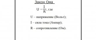
Using Ohm's law, we calculate the current flowing in this circuit.
As you can see, knowing the parameters of the circuit, it is easy to calculate the missing values.
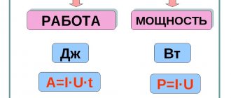
And remembering how power is calculated, it is easy to calculate the parameters of the capacitor based on the power consumption of the load.
Keep in mind that in such a circuit you cannot use polarized capacitors, that is, those that are included in the electronic circuit in strict accordance with the indicated polarity.
In addition, it is necessary to take into account the network frequency f
. And if in Russia we have a frequency of 50Hz, then for example in America the frequency is 60Hz. This also affects the final calculations.
A simple LED power supply circuit with a capacitor
Let's look at a device without a transformer power supply for LEDs using the example of a factory LED lamp driver.
- R1 – 1W resistor, which reduces the significance of voltage drops in the network;
- R2,C2 – the condenser serves as a current limiter, and the resistor is for discharging it after disconnecting from the network;
- C3 – smoothing condenser, to reduce light pulsation;
- R3 - serves to limit voltage drops after conversion, but it is more advisable to install a zener diode instead.
Comments: 42
The need to connect an LED to the network is a common situation. This includes an indicator for turning on devices, a backlit switch, and even a diode lamp.
This is what the wiring diagram for a table LED lamp would look like. And powerful ten-watt resistors at low room temperatures could be used as an additional heating source.
The use of conductors as a current limiter allows one to significantly reduce the dimensions of such a circuit. This is what the power supply for a 10-15 W diode lamp looks like.
The principle of operation of circuits using a ballast capacitor
In this circuit, the condenser is a current filter. Voltage is supplied to the load only until the condenser is fully charged, the time of which depends on its capacity. In this case, no heat generation occurs, which removes restrictions on load power.
To understand how this circuit works and the principle of selecting a ballast element for an LED, let me remind you that voltage is the speed of electrons moving along the conductor, and current is the electron density.
For a diode, it is absolutely indifferent at what speed electrons will “fly” through it. The calculation of the conductor is based on the current limitation in the circuit. We can apply at least ten kilovolts, but if the current is several microamps, the number of electrons passing through the light-emitting crystal will be enough to excite only a tiny part of the light emitter and we will not see the glow.
At the same time, at a voltage of several volts and a current of tens of amperes, the electron flux density will significantly exceed the throughput of the diode matrix, converting the excess into thermal energy, and our LED element will simply evaporate in a cloud of smoke.
If there is no powerful zener diode
When there is no zener diode of suitable power, it can be fully replaced with a diode-transistor analogue.
But then the BTBP should be built according to the scheme shown in Fig. 2. Here, the current flowing through the zener diode VD2 decreases in proportion to the static current transfer coefficient of the base of the powerful npn transistor VT1. The voltage of the UCT analogue will be approximately 0.7V higher than Ust of the lowest-power zener diode VD2 if the transistor VT1 is silicon, or by 0.3V if it is germanium. A pnp structure transistor is also applicable here. However, then the circuit shown in Fig. is used. 3.
Calculation of a quenching capacitor for an LED
Let's look at the detailed calculation; below you can find the online calculator form.
Calculation of capacitor capacity for an LED:
C(uF) = 3200 * Isd) / √(Uin² - Uout²)
C µF – capacitance of the condenser. It should be rated at 400-500V; Isd – rated current of the diode (see the passport data); Uin – amplitude network voltage - 320V; Uout – rated LED supply voltage.
You can also find the following formula:
C = (4.45 * I) / (U - Ud)
It is used for low-power loads up to 100 mA and up to 5V.
Calculation of a capacitor for an LED (online calculator):
For clarity, we will calculate several connection diagrams.
General concept
A capacitor consists of two conductive plates and a dielectric between them. And that's it, nothing more. It looks like a simple radio component, but it works differently at high and low frequencies.
Indicated on the diagram by two parallel lines.
Principle of operation
This radio component demonstrates well the phenomenon of electrostatic induction. Let's look at it with an example.
If you connect a constant current source to the capacitor, then at the initial moment of time the current will begin to accumulate on the plates of the capacitor. This occurs due to electrostatic induction. Resistance is practically zero.
The electric field, due to electrostatic induction, attracts opposite charges to two opposite plates. This property of matter is called capacity. All materials have a capacity. And even for dielectrics, but for conductors it is much greater. Therefore, the capacitor plates are made of conductor.
The larger the capacitance, the more charges can accumulate on the capacitor plates, i.e. electric current.
The main property of a capacitor is capacitance. It depends on the area of the plates, the distance between them and the dielectric material that fills the space between the plates.
As charges accumulate, the field begins to weaken and the resistance increases. Why is this happening? There is less and less space on the plates, like charges on them act on each other, and the voltage on the capacitor becomes equal to the current source. This resistance is called reactive or capacitive. It depends on the frequency of the current, the capacitance of radio components and wires.
When there is no room left on the plates for the electric current, the current in the circuit will stop. Electrostatic induction disappears. Now there remains an electric field that holds the charges on its plates and does not let them go. And the electric current has nowhere to go. The voltage across the capacitor will become equal to the emf (voltage) of the current source.
What happens if you increase the EMF (voltage) of the current source? The electric field will begin to put more and more pressure on the dielectric, since there is no more space on the plates. But if the voltage on the capacitor exceeds the permissible limits, the dielectric will break through. And the capacitor will become a conductor, the charges will be released, and the current will flow through the circuit. How then to use a capacitor for high voltages? You can increase the size of the dielectric and the distance between the plates, but this reduces the capacitance of the part.
Between the plates there is a dielectric that prevents the passage of direct current. This is precisely the barrier to direct current. Because constant current also creates constant voltage. And a constant voltage can create electrostatic induction only when the circuit is closed, that is, when the capacitor is charging.
This way the capacitor can store energy until a consumer connects to it.
Capacitor and DC circuit
Let's add a light bulb to the diagram. It will only light up while charging.
Another important feature is that when the current charging process occurs, the voltage lags behind the current. The voltage seems to catch up with the current, since the resistance increases smoothly as it charges. Electrical charges take time to move to the capacitor plates. This is the charging time. It depends on capacitance, frequency and voltage.
As it charges, the light begins to glow dimmer.
The light goes out when fully charged.
Direct electric current does not pass through the capacitor until it is charged.
AC circuit
What if you change the polarity on the current source? Then the capacitor will begin to discharge and charge again as the polarity of the source changes.
Electrostatic induction occurs constantly if the electric current is alternating. Every time the current begins to change its direction, the process of charging and discharging begins.
Therefore, the capacitor passes alternating electric current.
The higher the frequency, the lower the reactance (capacitive) resistance of the capacitor.
RC chain
RC circuit of integrating type
What happens in this circuit if switch S1 is closed?
Capacitor C is initially discharged and the voltage across it is early 0. Therefore, the current at the first moment will be equal to I=U/R. Then the capacitor will begin to charge, the voltage across it will increase, and the current through the resistor will begin to decrease. I=(U-Uc)/R. This process will continue, the capacitor will be charged with a decreasing current to the source voltage U. The voltage on the capacitor will increase exponentially.
Fig. 11. Graph of voltage growth on the capacitor when applying voltage of value U (steps).
Question: And if you power such a circuit from a current generator, how will the voltage across the capacitor increase?
As noted above, the current at the first moment after applying the voltage will be equal to I=U/R, since the capacitor is discharged and the voltage on it is 0. And for some time, while the voltage on the capacitor Uc is small compared to U, the current will remain almost constant. And when charging a capacitor with direct current, the voltage across it increases linearly.
Uc=Q/C, and we remember that current is the amount of charge per second, that is, the rate of charge flow. In other words, the charge is the integral of the current.
Q = ∫ I * dt = ∫ U/R * dt
Uc=1/RC * ∫ U * dt
But all this is close to the truth at the initial moment, while the voltage on the capacitor is low.
What it really comes down to is that the capacitor is charged by a constant current. A direct current is produced by a current generator. (See the question above) If the voltage source produces an infinitely large voltage and the resistance R also has an infinitely large value, then in fact we already have an ideal current generator, and external circuits do not affect the value of this current.
RC chain of differentiating type
Well, everything here is the same as in the integrating chain, only in reverse.
Figure 12. Differentiating chain.
The properties of RC circuits are well covered on the Internet.
