Cable parameters are calculated when designing an electrical line. The thorough approach of the engineers guarantees high-quality and safe wiring, designed with a margin for the simultaneous operation of all electrical appliances. If you ignore accuracy at this stage and choose the wrong electrical cable, everything can end in a fire.
To prevent emergency situations that may entail significant financial costs, it is recommended to pre-calculate the cable cross-section depending on the length and power. You can do this in several ways:
- using online calculators - software services that work on the basis of approved formulas;
- according to the tables of the dependence of the cross-section of the wire core on the power and length of the line;
- according to formulas.
Calculator for calculating cross-section by power and length
So that the task of calculating wiring parameters does not seem unsolvable to beginners, a calculator has been developed for calculating cable cross-section by power and length.
| Convert Watts to Amperes | ||
| U, V | P, Watt | Potential current, A |
| Uarb, V | Current consumption, A | Cable type | S, mm2 | Length, m |
| 1 | delete |
| № | Ubp, V | Uarb, V | Current consumption, A | Cable type | S, mm2 | Length, m |
| 1 | delete |
| № | Ubp, V | Uarb, V | Current consumption, A | Cable type | S, mm2 | Length, m |
| 1 | delete |
| № | Ubp, V | Uarb, V | Current consumption, A | Cable type | S, mm2 | Length, m |
| 1 | delete |
With its help, it is easy to determine the current consumption value of electrical installations, knowing the maximum power they consume. This parameter is usually indicated by the manufacturer directly on the device or in its passport. The supply voltage can be found there.
The maximum permissible line length is calculated for a specific cable type, which is selected from the drop-down list. Also included in the calculation are the values of current consumption, power supply voltage and the minimum voltage at which the device is capable of operating.
The online calculator significantly simplifies the work of designers, reducing time for manual calculations.
Preliminary power calculation
This stage comes first because the collected data will serve as the basis for the design.
It is impossible to start designing if the range of connected devices, their power and operating mode are not known. At the same time, the type of electrical equipment is more important than power when choosing a cable cross-section on a calculator.
For example, devices with the same rated power can operate in different modes, which affects peak loads - the operation of a 3 kW hot water boiler is one thing, the operation of a 3 kW well pump is another matter. After all, when the pump is turned on, within a few seconds the power consumption exceeds the rated power by 30-45%. Such a jump will definitely blow out the fuse plugs if this factor was not taken into account at the first stage of selecting the cable cross-section on the calculator.
The power of the connected equipment is taken from the product passport, and it is better to divide the list of all electrical appliances at a given facility into specific rooms.
Design and calculation of cable cross-section using an online calculator
The stage seems chaotic due to the abundance of small details of the project, but dividing the object into several rooms, as it were, reveals the scenario of the work, allowing us to assess the scale of the task through the prism of one room.
Each room is drawn separately on a sheet of paper, and a list of electrical appliances for a specific room is entered.
Connection points are determined and corresponding devices are linked to them.
For example, in the hall of a three-room apartment it is planned to use:
- Air conditioning 2 kW;
- TV 0.4 kW;
- LED lighting with a total power of 200 watts;
- Music center 0.5 kW;
- Gadgets and other small household appliances with a total power of 1 kW.
For ceiling lighting, a separate line of 2 x 1.5 mm2 is thrown.
A separate circuit is laid for the air conditioner; the wire cross-section is calculated as follows: 2000/220 = 10 A (rounded up). Add 5 A (margin of safety) and select a wire for a current of 15 Amperes.
The remaining devices consume a total of 2.1 kW. Considering that the chance of their simultaneous activation is unlikely, you can use the formula for calculating the cable cross-section for an air conditioner.
Based on calculations for one room, using an online calculator, calculations are carried out for all electrical wiring. But some rules must be taken into account:
For high-power electrical appliances, such as: boiler, electric stove, heated floors, etc., a separate power supply line is laid with an individual circuit breaker and RCD;
Rooms with high humidity, such as a bathroom and kitchen, are powered via a separate circuit from the panel, regardless of the total load;
Separately lay a line in each room for ceiling lighting;
Only copper wires are allowed to be used inside the apartment.
Selection by table
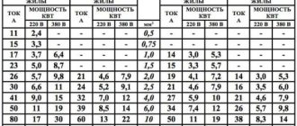
When you need to determine approximate wiring parameters, having individual values, a table for selecting cable cross-section by power and length will come in handy.
| Power, W) | Current (A) | 1.5 sq. mm | 2.5 sq. mm | 4 sq. mm | 6sq.mm | 10 sq. mm | 16sq.mm | 25sq.mm | 35sq.mm | 50sq.mm | 70sq.mm | 95sq.mm |
| 500 | 2,3 | 100 m | 165 m | 265 m | 395 m | |||||||
| 1 000 | 4,6 | 30m | 84m | 135 m | 200m | 335 m | 530 m | |||||
| 1 500 | 6,8 | 33 m | 57 m | 90m | 130m | 225 m | 355 m | 565m | ||||
| 2 000 | 9 | 25m | 43 m | 68m | 100 m | 170m | 265 m | 430 m | 595 m | |||
| 2 500 | 11,5 | 20m | 34m | 54m | 80m | 135 m | 210 m | 340m | 470 m | 630 m | ||
| 3 000 | 13,5 | 17 m | 29m | 45 m | 66m | 110 m | 180 m | 285 m | 395 m | 520 m | ||
| 3 500 | 16 | 14 m | 24 m | 39m | 56m | 96m | 155m | 245 m | 335 m | 450 m | ||
| 4 000 | 18 | 21m | 34m | 49 m | 84m | 135 m | 210 m | 295 m | 395 m | 580m | ||
| 4 500 | 20 | 19 m | 30m | 44m | 75m | 120 m | 190 m | 260m | 350 m | 515 m | ||
| 5 000 | 23 | 27m | 39 m | 68m | 105 m | 170m | 235 m | 315 m | 460m | 630 m | ||
| 6 000 | 27 | 23 m | 32 m | 56m | 90m | 140 m | 195 m | 260 m | 385m | 530 m | ||
| 7 000 | 32 | 28m | 48m | 76m | 120m | 170 m | 225 m | 330 m | 460 m | |||
| 8 000 | 36 | 42 m | 67 m | 105 m | 145 m | 195 m | 290m | 400m | ||||
| 9 000 | 41 | 38m | 60m | 94m | 130m | 175 m | 255 m | 355 m | ||||
| 10 000 | 45 | 34m | 54m | 84m | 120 m | 155 m | 230 m | 320 m | ||||
| 12 000 | 55 | 45 m | 70m | 92 m | 130m | 190 m | 265 m | |||||
| 14 000 | 64 | 38m | 60m | 84m | 110 m | 165 m | 230 m | |||||
| 16 000 | 73 | 53 m | 74 m | 99m | 145 m | 200m | ||||||
| 18 000 | 82 | 47 m | 65m | 88m | 125m | 175 m | ||||||
| 20 000 | 91 | 160m | 160m | 160m | 160m |
Knowing the total power of electrical appliances and the approximate length of the line, using the table you can determine the minimum permissible cross-section of the wire. Values must be rounded up.
Example. The total power of the electrical devices is 4.3 kW, the line length is 40 m. Rounding these values towards larger tabular values, we can determine that the wire cross-section under such conditions should be 6 mm2.
Table of wire sections and diameters
Sometimes, instead of fiddling with wires with a ruler, it is much easier to use ready-made tables. One of them will be given below with some abbreviation. In such a table, the left column will indicate the specific diameter of the wire strands, and the right column will indicate the cross-section of the conductor in square millimeters.
Section definition:
- 0.8 mm2 – 0.5;
- 1 mm2 – 0.75;
- 1.1 mm2 – 1;
- 2.28 mm2 – 6;
- 3.2 mm2 – 8;
- 4 mm2 – 8.3.
The table above is far from complete. In total there are about 10-12 lines in it, and each of its meanings can easily be found in a store. The most accurate information on each specific type of wires and cables will be provided upon request by a sales consultant in a household appliances or electrical goods store.
The following characteristics may also be useful. For example, the table may also indicate whether the wire is laid open, how many wires are in one connection and what exactly they are, for example, 2, 3, 4 single-core or 1 two-wire, 1 three-wire.
These points are also very important, which is why, when planning to install a wire and calculate its cross-sectional area, such details should still be clarified and measured for the sake of peace of mind and comfort. An error threatens the failure of all electronics (TVs, desktop computers, refrigerators, electricity and even washing machines), as well as a fire hazard in your own home. That is why, when choosing any wires or cables at home, a thrifty owner must be an extremely attentive, demanding and careful buyer.
Calculation formula
The formula for calculating cable cross-section by power allows you to determine the desired value more accurately than using a table. This calculation option is recommended to be chosen in controversial situations, as well as in cases where the accuracy of the calculation is important.
If the line is long, the cross-section of the wire directly depends on its length. This is due to power losses due to the presence of resistance in the metal. As the cable lengthens, resistance increases and power decreases. To compensate for losses, it is necessary to select the correct wire cross-section. It
L – length of wiring, m;
I – load current of electrical appliances, A;
Ustart – supply voltage, V;
Ukon – operating voltage of electrical appliances, V;
ρ – resistivity of copper or aluminum, Ohm×mm2/m.
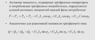
Knowing the power of electrical appliances, you can calculate the current using the formula:
P – power consumption of electrical installations, W;
U – supply voltage, V.
Different ways: how to determine the wire cross-section
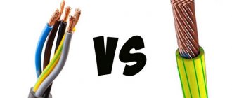
A conductor is often referred to by two different words – wire and cable. This mixture is very inconvenient. In everyday life, these concepts are often confused, although there are some significant differences in the operation of these devices. In order to correctly determine and correctly find out the cross-sectional area, it is necessary to understand the differences between these conductors and understand a more or less accurate definition.
A conductor consists of a group of cores that are enclosed in separate insulation or in common insulation. The cores come in different types, usually woven or solid, depending on the wire model. Their diameter is measured both with a regular ruler and with a special device - a caliper. As a rule, conductors are made of various non-ferrous metals.
Typically the materials are as follows:
- Copper;
- Aluminum;
- Aluminum copper – (this is an alloy of aluminum and copper specially developed by scientists).
All these materials are distinguished by a relatively low price, low electrical resistance, fairly high electrical conductivity, ease of welding and installation
Another important characteristic is the minimal weight of the metal wire. The methods for finding the cross-sectional area of the above conductors are almost the same, and measuring it is not difficult at all
P=IU
These formulas are used in cases of active load (consumers in residential premises, light bulbs, irons).
For reactive loads, a coefficient of 0.7 to 0.9 is mainly used (for the operation of powerful transformers, electric motors, usually in industry). The following table suggests the initial parameters - current consumption and power, and the determined values - wire cross-section and tripping current of the protective circuit breaker.
Based on the power consumption and current, select the cross-sectional area of the wire and the circuit breaker.
Knowing the power and current, you can select the wire cross-section in the table below.
Table 2.
| Max. power, kWt | Max. load current, A | Wire cross-section, mm2 | Circuit breaker current, A |
| 1 | 4.5 | 1 | 4-6 |
| 2 | 9.1 | 1.5 | 10 |
| 3 | 13.6 | 2.5 | 16 |
| 4 | 18.2 | 2.5 | 20 |
| 5 | 22.7 | 4 | 25 |
| 6 | 27.3 | 4 | 32 |
| 7 | 31.8 | 4 | 32 |
| 8 | 36.4 | 6 | 40 |
| 9 | 40.9 | 6 | 50 |
| 10 | 45.5 | 10 | 50 |
| 11 | 50.0 | 10 | 50 |
| 12 | 54.5 | 16 | 63 |
| 13 | 59.1 | 16 | 63 |
| 14 | 63.6 | 16 | 80 |
| 15 | 68.2 | 25 | 80 |
| 16 | 72.7 | 25 | 80 |
| 17 | 77.3 | 25 | 80 |
Critical cases in the table are highlighted in red; in these cases, it is better to play it safe without saving on the wire, choosing a thicker wire than indicated in the table. On the contrary, the current of the machine is less.
Using the table, you can easily select the wire cross-section by current, or the wire cross-section by power. Select a circuit breaker for the given load.
In this table, all data is given for the following case.
- Single phase, voltage 220 V
- Ambient temperature +300С
- Laying in the air or in a box (located in a closed space)
- Three-core wire, in general insulation (cable)
- The most common TN-S system is used with a separate ground wire
- In very rare cases the consumer reaches maximum power. In such cases, the maximum current can operate for a long time without negative consequences.
It is recommended to choose a larger cross-section (next from the series), in cases where the ambient temperature is 200C higher, or there are several cables in the bundle
This is especially important in cases where the operating current is close to the maximum
In doubtful and controversial points, such as:
high starting currents; possible future increase in load; fire hazardous premises; large temperature changes (for example, the wire is in the sun), it is necessary to increase the thickness of the wires. Or, for reliable information, refer to formulas and reference books. But basically, tabular reference data is applicable for practice.
You can also find out the thickness of the wire using an empirical (experienced) rule:
The rule for choosing the cross-sectional area of the wire for the maximum current.
The required cross-sectional area for a copper wire, based on the maximum current, can be selected using the rule:
The required wire cross-sectional area is equal to the maximum current divided by 10.
Calculations according to this rule do not have a margin, so the result must be rounded up to the nearest standard size. For example, you need a wire with a cross-section of mm, and a current of 32 Amps. It is necessary to take the nearest one, of course, in the larger direction - 4 mm. It can be seen that this rule fits well into the tabular data.
It should be noted that this rule works well for currents up to 40 Amperes. If the currents are greater (outside the living room, such currents are at the input) - you need to choose a wire with an even larger margin, and divide not by 10, but by 8 (up to 80 A).
The same rule applies to finding the maximum current through a copper wire if its area is known:
The maximum current is equal to the cross-sectional area, multiplied by 10.
What affects the heating of wires
The number of cores and their type for the VVG cable
When using household appliances, the wiring often gets hot. Overheating occurs due to several factors:
- Incorrect choice of conductor cross-sectional area. The thicker the cores a cable has, the more current it transmits without overheating. You can find out the required parameters by the product labeling or after measurements with a caliper.
- Inconsistency of manufacturing materials. Copper wire transmits voltage better and has low resistance. Aluminum conductors heat up more with high resistance.
- Number of cores A single-core conductor with a thick rod has a high current transmission force. Multicore modifications are flexible, but have a lower maximum current transmission power.
- Installation specifics. When tightly laid in a pipe, the cables heat up more than when the wiring is open.
- Features of insulation. Inexpensive materials with low-quality insulation are not resistant to deformation and temperature influences.
What are the dangers of incorrectly installed electrical wiring: how hidden risks manifest themselves
Since the beginning of the summer season, a new neighbor brought his friend Andrei to me. He has a request: help resolve the issue with low voltage in his area. He is particularly concerned about the low levels in the garage where he has set up his electrical workshop.
Let's go have a look and check. Voltage is supplied to the input panel of a private house. My pocket multimeter showed 203 volts, which is generally acceptable for rural areas.
But then miracles began. On its large territory there are several outbuildings. They are connected in a daisy chain: one to the other. The garage is at the very end.
The total length of the highway exceeds one hundred meters. The connection was made with what was at hand: 1.5 mm square copper wire, and individual sections between buildings were powered even with 2.5 square meter aluminum strands.
This area has increased resistance. It creates a voltage drop at the entrance to the garage of up to 185 volts. And this is no longer enough for the normal operation of electric motors of various machines.
Andrey’s losses in the area from his house to his workshop amounted to 18 volts. He was going to buy a voltage stabilizer for the garage, and I explained to him that this could not be done for the following reasons:
- the stabilizer will raise the voltage level at its output and the power consumption of the machines will increase even more;
- This will further increase the load on the wiring.
In this situation, an additional voltage drop will occur at the input to the stabilizer, which will entail:
- disabling it from protection;
- or an emergency situation occurs in the wiring due to its overload and overheating.
Unnecessary voltage losses can only be eliminated by correct selection of the cross-section of the power cable, taking into account the transmitted power and its reliable installation.
Features of calculating the power of hidden wiring
When calculating the power of hidden wiring, 20-30% is added to the resulting figure.
When the project indicates the possibility of laying hidden wiring, the diameter and parameters of the cable cross-section must be purchased with a reserve. 20-30% is added to the figure obtained after calculation. Such calculations exclude heating of the conductor in a closed space with minimal air access.
If several conductors are laid in closed channels, the thickness of each increases by 40%. For additional protection from overheating, each product is placed in an individual corrugated pipe.
About the aluminum wire.
Unlike copper, aluminum conducts electric current less well. For aluminum (a wire of the same cross-section as copper), at currents up to 32 A, the maximum current will be 20% less than for copper. At currents up to 80 A, aluminum transmits current worse by 30%.
Rule of thumb for aluminum:
The maximum current of an aluminum wire is equal to the cross-sectional area, multiplied by 6.
Having the knowledge gained in this article, you can choose a wire based on the ratios “price/thickness”, “thickness/operating temperature”, as well as “thickness/maximum current and power”.
(Addition to article, June 2014)
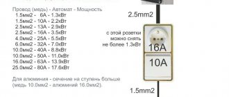
The Germans approach the maximum current depending on the cross-sectional area of the wire somewhat differently. A recommendation for choosing an automatic (protective) switch is located in the right column.
Table of the dependence of the electric current of the circuit breaker (fuse) on the cross-section. Table 3.
