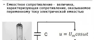
The use of capacitance in a DC circuit is familiar to every electronics engineer. In this case, the work of the part is described by relatively simple physical laws. Things are somewhat more complicated with alternating current, because with this use of capacitance it becomes necessary to take into account reactance.
Active and reactive components
Capacitance formula
When an alternating voltage is applied to the capacitor plates, the current through this element initially tends to its maximum value. As the device charges, it gradually decreases. At the same time, voltage behaves differently, i.e. smoothly increases from zero to the maximum value.
A similar effect is caused by capacitance. It depends both on the structure of the electronic device itself and on the characteristics of the alternating voltage applied to it.
Formula for calculating resistance
Where:
- XC – reactance, ohm;
- p – 3.14;
- f – frequency of alternating voltage applied to the plates, Hz;
- C – capacity, F.
Note! The capacity of an element can be recognized by the markings on its body. If it is unreadable or erased, then this value is determined using a multimeter. It must have a capacitance measurement function (approx. DT9208A).
Device characteristics
The most important characteristic of a storage device is capacity. The charging time depends on it when the device is connected to a power source. The discharge time is directly related to the value of the load resistance: the higher it is, the faster the process of releasing the accumulated energy occurs. This capacity is determined by the following expression:
C = E*Eo*S / d, where E is the relative dielectric constant of the medium (reference value), S is the area of the plates, d is the distance between them.
In addition to capacity, the capacitor is characterized by a number of parameters, such as:
- specific capacitance - determines the ratio of the capacitance to the mass of the dielectric;
- operating voltage - the nominal value that the device can withstand when applied to the plates of the element;
- temperature stability - the range in which the capacitance of the capacitor practically does not change;
- insulation resistance - characterized by the self-discharge of the device and determined by the leakage current;
- equivalent resistance - consists of losses generated at the terminals of the device and the dielectric layer;
- absorption - the process of the emergence of a potential difference on the plates after the device is discharged to zero;
- capacitance - a decrease in conductivity when alternating current is supplied;
- polarity - due to the physical properties of the material used in manufacturing, the capacitor can operate correctly only if a potential with a certain sign is applied to the plates;
- equivalent inductance is a parasitic parameter that appears on the contacts of the device and turns the capacitor into an oscillating circuit.
Vector representation of capacity
Active resistance
To simplify the understanding of the processes occurring in a capacitor under the influence of an alternating current source, it is convenient to use the vector representation of the capacitance.
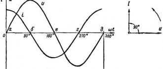
Vector diagram
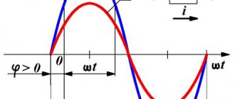
At the initial moment of charging the capacitor, the potential U on its plates is zero (point a). At the same time, current I has its maximum value (point b). At this stage, the lag is already noticeable. The current begins to decrease from its peak value (section bd). The voltage at this moment has not yet increased and is only approaching its maximum (ac).
This is reflected in the diagram on the right. At the moment when the voltage U has its lowest value (e), the current I just begins to move into the negative region (f).
Element l (inductance)
It is known that in inductance the phase relationship is ψu = ψi + 90°. For instantaneous power it has
.
Averaging equation (2.35) over time over the period T, we obtain
.
To quantify the power in the inductance, use the QL value equal to the maximum value pL
and call it reactive (inductive) power. The unit of measurement chosen was VAR (volt-ampere reactive). Equation (2.36) can be written in terms of the effective values of U and I and using the formula UL = I XL we obtain
Capacitance
Reactance
Capacitive, or reactive, resistance fundamentally depends on the frequency of the voltage. This relationship is clearly visible in the graph below. The higher the frequency, the lower the reactance. This is obvious from the above formula. The variable f (frequency) is in the denominator. Therefore, as it increases, Xc will decrease.
Frequency dependence
Capacitance in AC circuit
Impedance
When a constant voltage is applied to the capacitor, it will gradually charge to the maximum potential difference across its plates. After this, the current through the electronic component will stop and, apart from a negligible leakage, will be zero. Therefore, in a DC circuit, the capacitor has a huge resistance. In calculations, its value is taken equal to infinity.
Reactance has a completely quantifiable value. It can be measured using an oscilloscope, a generator and a fixed resistor. To do this you will need to assemble a circuit. In it, the capacitor forms a voltage divider with a resistor. An oscilloscope will be used to measure the potential that forms at the terminals of the capacitor.
For this scheme, the calculations are as follows.
Indirect measurement formula
Here:
- Ur – potential difference across the resistor, V;
- Uc – voltage on the plates, V;
- R – resistor resistance, ohm;
- Xc – capacitance resistance, ohm;
- I – current flowing in the circuit, A.
Indirect measurement
Important! The electrical cable also has a capacitance. Therefore, after removing the voltage, some charge remains on it. This phenomenon is dangerous for humans, especially if the conductor was at a potential of 1000 V or higher before disconnecting.
Element r (resistor)
Let's set the voltage and current in the form of ratios
It is known that for a resistor ψu = ψi, then for p we get
From equation (2.32) it is clear that the instantaneous power is always greater than zero and varies over time. In such cases, consider the average power over the period T
.
If we write Um and Im through the effective values of U and I: ,, then we get
The form of equation (2.34) coincides with direct current power. The value P equal to the product of the effective values of current and voltage is called active power. Its unit of measurement is Watt (W).
Example of capacitance calculation
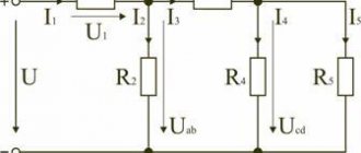
For the calculation you will need most of the listed physical quantities. They are indicated in the diagram and have the following meanings as an example:
- frequency f = 50 Hz (typical household network);
- capacitance C = 33 nF = 0.000000033 F = 3.3 * 10-8 F;
Example diagram
The reagent will be calculated using the formula described above:
Xc = 1/(2pfC).
In this case, the resistance of the capacitor in the AC circuit is 96.5 kOhm. If we write down all the calculations, we get the following.
Calculation example
The formula itself is not difficult. However, to carry out calculations, knowledge of a school algebra course is required, i.e. ability to work with powers, fractions and other mathematical algorithms. In practice, it makes sense to cheat a little. To avoid complex calculations every time, you can use one of the online calculators from the Internet. Such resources allow you to make a complex calculation and find out some other parameters of the circuit.
Properties of containers
The main property is their ability to accumulate and release electrical charge. Both of these processes do not occur instantly, but over a very definite period that can be calculated. This property is used to create various timing RC circuits. If you charge a capacitor to a certain value, then the time it takes to discharge through resistor R will depend on the capacitance C.
rc circuit
Another common property of capacitors is their ability to limit alternating current. It is caused by the reagent of these elements. The capacitance included in the alternating current circuit limits it to the value I = 2pfCU. Here U is the voltage of the power source.
Additional Information. A capacitance connected in parallel with a coil having an inductive reactance is called an oscillatory circuit. This circuit has a high oscillation amplitude at the resonant frequency. It is used to select from the many surrounding radio signals exactly the one for which you want to tune the reception.
Resistance is one of the characteristics of a capacitor connected to an alternating current circuit. Understanding the processes occurring with this element in such circuits significantly expands the scope of its use. The reactance of capacitors is taken into account both in simple household electrical appliances and in complex computer technology.
Examples of problem solving
EXAMPLE 1
| Exercise | The oscillatory circuit has a resistance (R), an inductor (L) and a capacitor C (Fig. 1). An external voltage is connected to it, the amplitude of which is equal to , and the frequency is . What is the amplitude of the current in the circuit? |
| Solution | The circuit resistance in Fig. 1 consists of the active resistance R, the capacitance of the capacitor and the resistance of the inductor. The total resistance of a circuit (Z) that contains the above elements is found as: Ohm's law for our section of the circuit can be written as: Let us express the desired current amplitude from (1.2), substitute the right-hand side of formula (1.1) instead of Z, and we have: |
| Answer |
Video
Coffee capsule Nescafe Dolce Gusto Cappuccino, 3 packs of 16 capsules
1305 ₽ More details
Coffee capsules Nescafe Dolce Gusto Cappuccino, 8 servings (16 capsules)
435 ₽ More details
Best Gaming Keyboards