Due to unstable voltage in houses and apartments, people are forced to install voltage stabilizers (hereinafter referred to as SV) to power the entire home or to operate a specific device. As with any other type of electrical appliance, sometimes a situation arises when the voltage stabilizer does not work (broken). Internal faults in most cases are associated with power circuits: relays, triacs, servo drive control unit, etc. Therefore, before you begin to analyze the malfunction and the cause of its occurrence, you need to understand what type of stabilizer you have failed. In this article, we will look at what types of voltage stabilizer malfunctions there are, why they occur, and how to fix them yourself (if possible).
Hum and clicks
If the voltage regulator is humming a lot, you need to check that the supply voltage is not above or below the permissible ranges. The adjustment range in most cases lies within 100-250 Volts.
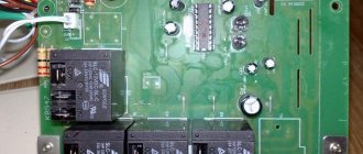
Attention! Even when in good condition, the autotransformer hums evenly and not too loudly. The servo drive also makes a hum when the brush assembly moves. Relay voltage stabilizers make clicking noises during operation. This is normal, the relays (black rectangles in the picture below) switch taps from the windings to regulate the output voltage.
If the device makes a loud noise, this may indicate sparking of the brush in servo-driven models, problems with the relay, and poor contact of the internal wiring of the device.
Shuts down under load
The voltage stabilizer does not support the load - this problem happens for a number of reasons. The first among them is increased load (consumer power). If you have not changed the connected devices, then the problem is in the stabilizer. If it does not turn off instantly, but after some time of operation, then this may be due to overheating or interturn short circuits of the autotransformer.
What to do: disassemble the device and carry out an external inspection of the windings of the autotransformer; if it is not too dusty, then check for signs of local overheating. If there is a lot of dust, clean it out
If there are signs of overheating and burning, the insulation of the windings is damaged. This is an interturn short circuit, then how to repair the stabilizer in this case? It is necessary to rewind or replace the autotransformer with one of the same or greater power. But the cost of such repairs can be comparable to purchasing a new voltage stabilizer.
Important! In servo-drive models, a number of malfunctions can be caused by brush wear and contamination of live parts with graphite shavings. During operation, the brush wears off, covering the autotransformer with graphite. Because of this, short circuits between current collectors and sections of turns and overheating can occur. In this case, you need to sweep away the graphite and clean it between turns. Make sure that the windings are laid evenly and there are no breaks. Clean the contact surface with a regular office eraser until it shines, especially the most used sector.
There is no 220 Volt output
The malfunction manifests itself in the fact that the stabilizer does not produce a voltage of 220 Volts. This does not necessarily indicate internal problems, the reason may be the mains voltage - it is too low, and the device simply does not pull. If the power is in the operating range of the stabilizer, then we will proceed with the repair.
What to do: in servo-driven models, failure can be caused by wear of the brush mechanism or the servo drive itself. It may not reach the end of the winding or the brush may not be in contact with its corresponding sector. In the simplest case, it may simply be contaminated with graphite. To repair it, you need to clean the surface of the contacts to a metallic shine. Sometimes you need to replace the brush.
Interesting! It also happens that due to contamination of the working sector of the brush assembly with graphite, the voltage often does not rise above a certain value.
In relay MVs, this most often indicates that one or more electromagnetic relays or their control cascade is faulty. It is usually built on a transistor. Relays can have different coil voltages, often 12 volts.
What to do: to check, apply voltage to the coil and ring the power contacts. They should close and open, the relay clicks. If this does not happen, either the contacts have stuck (more often), or the relay coil has burned out (less often). If the relay is working properly, check the transistor; it should not be broken, and the emitter-base and collector-base junctions should ring in one direction, like a diode. Use any low-power transistors of similar conductivity.
In triac and thyristor MVs, the fault diagnosis is similar - you need to test the semiconductor power switch for breakdown and, if it fails, replace it with an analogous or more powerful one.
Frequently asked questions and answers about voltage stabilizers
Frequently asked questions and answers about voltage stabilizers
Hello, can you tell me what method can be used to correctly calculate the power of a single-phase stabilizer for an apartment? Option one is to ask an electrician (recommended). Option two is to find out the power of all consumers in the apartment and add it up.
I want to repair the voltage stabilizer myself, please send me the diagrams. We cannot provide you with the stabilizer diagram. If you have any questions or would like to have your stabilizer repaired, please contact our service center. The address and telephone number of the service center are indicated on the warranty card.
What is the delay button for? The “delay” button allows you to select the time interval between turning on the stabilizer and turning on the load.
What is “Bypass” and what is it for? “Bypass” is the second switch in a two-pole circuit breaker that connects the input to the output without stabilization. Bypass is used when voltage stabilization is not needed or impossible.
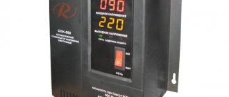
This morning I discovered that the display did not show the usual 220, but numbers varying from 213-216 and the “Network” and “Output” signal lights were blinking. This means that the input voltage was outside the operating range of the stabilizer (145 - 260 V). At the same time, the real output voltage is displayed on the screen and the lights flash. If the input voltage has returned to the operating range, the device readings should return to normal.
Is there a wiring diagram for the Resant voltage stabilizer? I don’t know how to turn it on. The stabilizer must be connected to the network by an electrician.
The stabilizer does not output 220V, but jumps within 206V-230V. The passport for the stabilizer indicates the output voltage: 220V ± 8%. This means that the output voltage can change in the range from 202.4 V to 237.6 V. If your input voltage changes, then your output voltage will also change, but only in the range from 202.4 V to 237.6 V.
Why does the input circuit breaker in the switchboard knock out when connecting the stabilizer? Most likely, you have low voltage in the network. The stabilizer increases the output voltage, but at the same time the input current increases. Thus, less current passes through your machine without a stabilizer than with it. If your machine does not have a power reserve, then when you connect a stabilizer it will work. Install a machine equal in power to the machine on the stabilizer.
The stabilizer turns off spontaneously after pressing the start button. Spontaneous shutdown is a protective shutdown of the stabilizer. Protective shutdown occurs in the following cases: 1. The load of consumers exceeds the permissible value. 2. Autotransformers overheated (mainly due to overload). 3. There was a voltage surge that the stabilizer could not smooth out. 4. The input voltage is outside the operating range.
Tell me, is it possible to turn on a semi-automatic welding machine with a power of 3.5 through your voltage stabilizers (electromechanical or relay). 4kW? Via electromechanical is possible. When calculating the rating of the stabilizer, you need to multiply the power of the welding machine by 3 times. If at the same time you have a low input voltage, then feel free to multiply by 5 times.
Tell me, should the built-in cooling fan run constantly or does it turn on at a certain temperature inside the case? The fan turns on when the autotransformer heats up to 65 degrees.
All sections
Source
Poor voltage stabilization
If the voltage stabilizes in too large steps, and before everything was smooth, then the breakdown is close to the previous one - the switching device has failed at one or more adjustment stages. The algorithm for checking voltage stabilizer malfunctions and their elimination are described in the previous paragraph.
Attention! The characteristics of each stabilizer describe either the adjustment step or the boundaries of each stage, as well as the accuracy of maintaining the rated output voltage.
In servo-drive stabilizers, this occurs when there is a breakdown in the engine gear mechanism, as well as when the windings are dirty, as was the case in the cases described above. Gearbox malfunctions may be accompanied by an uneven buzzing or crackling sound - this is the gears slipping.
What to do: you need to disassemble the mechanism and if all parts are normal, replace the lubricant.
It is also worth noting that servo-driven MVs may lack stabilization and may not work correctly due to the failure of the semiconductor motor control switches. Then the slider with the brush moves to one of the extreme positions or does not move at all.
Voltage stabilizer errors
A voltage stabilizer is an electronic or electromechanical equipment designed to modify an unstable input voltage (high, low, or “jumping”) into a stable output voltage.
Considering that the quality of electricity is not the same everywhere, the scope of use of stabilizers is unusually wide. They are installed in apartments, private houses, offices, industrial enterprises and any other facilities equipped with electrical appliances. The main function of voltage stabilizers is to protect expensive equipment: computers, computer networks, refrigerators, machine tools, air conditioners, boilers. Household and industrial stabilizing devices are the most effective way to protect such equipment.
At the same time, malfunctions and errors of voltage stabilizers are a common occurrence. The specialists of the engineering company 555 repair electronic equipment and are ready to fix any problem as soon as possible.
The machine does not turn on or crashes after the timer report
Most stabilizers do not enter operating mode immediately after switching on, but after a temporary delay. But after the report, the start-up timer does not occur, and the display indicator shows the letter N. An example of repairing a device with such a malfunction is discussed in the following videos:
For your information, the error code “H” indicates that the network voltage is too high and the protection has tripped. This is valid for devices, "Luxeon" and some others.
Interesting: the letter “H” means “High” or “High”, and L means “low”, “Low”. The resistor, the replacement of which you saw in the video, is responsible for the response thresholds for the upper and lower voltage levels. Due to incorrect resistance, the stabilization board cannot do its job and goes into protection.
Such symptoms or another malfunction code may be accompanied by the breakout of the circuit breaker supplying the stabilizer itself after the turn-on delay timer reports. In this case, the problem is solved by replacing the relays, which, if stuck, may result in increased current consumption.
Error codes and their descriptions when operating the Leader voltage stabilizer
| Material rating: |
, added Guest 08/26/2018 Posted in the category: Manuals / In these modes, the operation of the stabilizer is determined by the presence or absence of automatic bypass elements (optional).
In the absence of automatic bypass elements, the stabilizer in the event of an accident turns off the consumer and indicates the cause of the accident. Further operation of the stabilizer is possible only after turning it on again when the situation normalizes. When automatic bypass elements are installed, the operation of the stabilizer is determined by setting the bypass “B-000” or “B-001” when pressing the “menu” button in the parameter setting mode.
When setting the parameters “B-000”, in the event of an accident, the stabilizer turns off consumers and indicates the cause of the accident.
Further operation of the stabilizer is possible only after restarting or normalization of the situation.
When setting the parameter “B-001”, in the event of an emergency, the stabilizer will turn on the bypass, supplying voltage to consumers directly from the network, bypassing the control circuit.
The display alternately displays information about the fault code and information about turning on the bypass in the form of “A-007” and “B-220”, where 220 is the voltage value at the load.
Shows no signs of life or other damage at all
The most frightening malfunction is when, after applying voltage, neither the indicators light up nor the output voltage appears, i.e. when the voltage stabilizer does not work at all. In this case, the control board may fail. Most often, repairs begin with a visual inspection, paying attention to:
- burnt out paths;
- swollen electrolytic capacitors;
- burnt, cracked or exploded board components;
- microcracks on soldered contacts and cold soldering.
All identified deficiencies are eliminated, and if the external inspection does not produce results, they proceed to checking the board for broken tracks and short circuits with a multimeter in resistance and continuity measurement mode. Such repair of a stabilizer may require deep knowledge of electronics, electrical circuit diagrams, and in the most difficult cases, the use of an oscilloscope to check control signals and the logic of the circuit.
That's all we wanted to tell you about voltage stabilizer malfunctions and how to fix them yourself. We hope that now you know what to do in this or that case and why breakdowns occur!
It will be useful to read:
- How to use a multimeter
- What to do if the network voltage is low
- Dishwasher malfunctions
Resanta voltage stabilizers are used in many homes to ensure stable operation and protect the “health” of electrical appliances. As a result, home appliances work for a long time and undergo almost no repairs.
It must be said that the voltage stabilizer itself also requires compliance with operating conditions and periodic maintenance. Otherwise, the device may fail and require repair. In addition, after serving for a sufficiently long time, the device may break down simply due to wear and tear of parts.
This article is devoted to the delicate points of the Resanta brand stabilizers. Let's look at how failed parts are repaired and the device is restored to full functionality.
Principle of operation
The structural structure of the Resanta voltage stabilizer is as follows:
- automatic type transformer;
- the electronic unit;
- voltmeter;
- a control element that is responsible for starting and turning off certain windings.
This manufacturer produces many different types of stabilizers , so these winding connections will also vary. We will talk about all these nuances a little later, while considering the repair procedure.
In this design, the decisive factor is the electronic unit, which exercises general control of the entire system of the unit. He is responsible for the operation of the voltmeter, and also receives information about the power of the input voltage. Then, the block compares the obtained values with the optimal ones, determining the next action, i.e. whether it is necessary to add a few volts or, on the contrary, to subtract a certain amount.
Next, along the chain, is the determination of the necessary windings - which ones need to be started and which ones need to be turned off. Then, the electronic unit carries out one of these actions, after which all electrical appliances in the apartment receive a stable current.
Of course, the stabilization process itself may be slightly different, depending on the type of device being manufactured.
This difference applies to the types of windings, as well as the methods of starting and stopping them. Today, the Resanta company produces two types of these stabilizers:
- Electromechanical type.
- Relay.
Difficulty of repairing voltage stabilizers
All stabilization devices are equipped with protective functions, with the help of which technical indicators are monitored for compliance with the declared data and operating conditions. Each model has its own protective system, but there is a common understanding of exceeding the permissible limits, which does not allow the device to continue working.
First of all, you need:
- checking for short circuits, input and output voltage, temperature conditions of components;
- study the error code displayed on the display.
It is most difficult to determine the malfunction of the triac switches of the device, since their control is associated with knowledge of electronics. When making repairs, you cannot do without a circuit diagram, measuring instruments, including an oscilloscope. Using the control points of the recorded oscillograms, damage in the structural module of the device is determined. Then each radio component and assembly will be checked for defects.
In relay-type stabilizers, the cause of problems is often the relay designed to switch the transformer windings. Frequent switching of relay contacts leads to their burnout, jamming, or burnout of the coil itself. If the voltage disappears or an error message appears, it is worth checking all the relays.
The simplest repair is an electromechanical stabilizer, in which the operation and response to changes in network parameters become obvious immediately after removing the housing. It is not without reason that the simple design and high stabilization accuracy make these models very widespread.
Advantages of repairing voltage stabilizers at Engineering Company 555
- Highly professional and experienced team.
- Extensive experience in repairing household and industrial voltage stabilizers.
- Affordable prices.
- Free inspection of the device to determine its repairability.
- Cost savings compared to purchasing new equipment.
- Prompt execution of work of any complexity.
- Efficient execution of any repair.
Contact us from anywhere in Russia. We can work with voltage stabilizers of any type and brand and guarantee our clients optimal results.
Types of voltage stabilizer malfunctions
Electromechanical type repair
A common problem with such devices is overheating. Therefore, the device should be serviced once every 2 months. An important part of the repair is the cleaning of the elements.
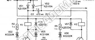
An example is typical failures of the common stabilizer ASN-10000/1-EM. The device consists of three identical parts - three 1-phase stabilizers designed to stabilize only their phase. The heart of the device is a step-up autotransformer. Together with the contactor and the input circuit breaker, it belongs to the power section.
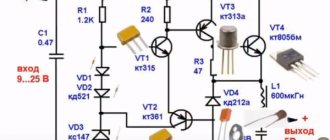
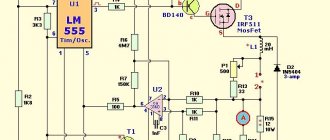
The schematic diagram of ASN-10000/1-EM is shown in the figure below.
The principle of operation of electromechanical equalizers is based on smooth regulation of output parameters. The voltage changes due to the sliding of an electrical contact along the winding of the autotransformer by means of an electrical drive. A slider is attached to the axis of the electric motor, which, by moving, normalizes the output parameters.
The following characteristic malfunction that occurs during the operation of electromechanical stabilizers and methods for its elimination deserve special attention - lack of stabilization of the output voltage.
The first sign of such a problem is the smell of smoldering parts. It is not without reason that the reversible motor is called the “Achilles heel” of electromechanical devices. The voltage stabilizer controller constantly monitors the value of the output parameters. The rotor rotates constantly and this gradually wears out the engine itself.
One malfunction can lead to others, for example, the failure of an entire motor control cascade assembled on a pair of transistors. In addition to these elements, resistors located in their collector circuit melt due to overheating.
Of course, it is better to replace a worn-out electric motor, but sometimes a skillful attempt to power it is crowned with success. This is the easiest way to revive the engine:
- disconnecting the engine from the circuit;
- supplying 5 V to its pins from a powerful power source, for example, from an ATX computer power supply.
This results in annealing of small “garbage” on the motor brushes. The normal current consumption of the engine should not go beyond 90–160 mA. Since the motor is of a reversible type, the voltage must be applied at least twice with a change in polarity. After these impacts, the performance of the unit is temporarily restored.
Another solution to the problem is a slight replacement of the circuit with a narrowing of the adjustment range. The brush will simply move differently, bypassing the burnt-out sections of the transformer track.
Repair of relay stabilizers
Let's look at repairs as examples:
Resanta ASN-500/1-ts.
The most common errors are the messages "L" and "H", which represent the initial letters of the English words "low" and "high". That is, the indicators go beyond the acceptable parameters. On previous Resanta relay stabilizers with dial indicators, one could see a change in the output voltage in the range of 204–235 V when switching stages. On the current equipment, the recording shows 220 V, but in fact it is the same +- 6%, according to the passport data.
There is a problem with the relay switching slowly, which affects the protective shutdown of the air conditioning compressor. The fact is that the manufacturer uses cheap capacitors of very low quality. If you replace the electrolytes, the problem will be solved.
The main thing is not to forget about power. What is written on the body nameplate is true for an input voltage of 200 V; in reality, for a low voltage (170–180 V), the power should be 2 times less.
Resanta SPN-9000.
The operating principle of this relay stabilizer is based on stepwise regulation of the output voltage. Stabilization is provided by a microprocessor. Switching of the autotransformer taps is performed by five powerful relays, which are controlled by transistor switches. The stability of the output voltage depends on the switching resolution (5–20 V).
The main problem with SPN-9000 is burnt or stuck contacts in the relay. These problems quite often arise during the operation of the relay stabilizer. And also if the input voltage does not correspond to the range of threshold values, stabilization will not work. It happens that immediately when the device is turned on, the fuses are knocked out, and this is how the short-circuit protection is triggered.
Due to a relay malfunction, transistor switches “fly”. The relays must be replaced or restored. To do this, you need to remove the covers from the relay, then remove the moving contact, free it from the spring and carefully clean all relay contacts with sandpaper. Finally, clean all contacts with special gasoline and reassemble the relay in reverse order. Then solder all the transistors and check the integrity of the transitions. If necessary, replace the transistors with new ones.
If you need to connect, say, an electric oven (9 kW), to a stabilizer, then you cannot find a better device for this than the Resanta voltage stabilizer. And if minor defects arise, the service workshops will quickly and professionally eliminate them on the basis of warranty. Timely repairs are the key to the durability and reliability of the device even after the warranty period.
There are various breakdowns, and sometimes it is difficult to understand whether the operating conditions according to the instructions were simply not followed, or whether the device is faulty. However, problems can exist, and as a result, a problem may arise at the most inopportune moment. A repair company will always help you correctly establish the “diagnosis” and effectively eliminate them.
In the video: simple repair of the RESANTA stabilizer 15 kW 3 phase.
Simple repair of stabilizer RESANTA 15KW 3PHASE
Power surge and equipment burned out! What to do?
Common situation? We assure you that you are not alone who is looking for an answer to this question. And every year the number of victims of power surges increases. For example, not a month goes by on the popular YouTube without posting another video about the burnt-out equipment of Russian residents from various parts of Russia. And the reason for this is sudden surges and voltage drops in the electrical network.
We are sorry if you find yourself in a similar situation. To help you at least somehow, we recommend watching the first video - from it you will learn where to turn first.
Our company’s specialists remind you that the quality of Russian electrical networks, unfortunately, is not getting better from year to year. And the best way to protect your household appliances from breakdown is to prevent an emergency from occurring. Agree, it is much more pleasant not to cause the equipment to break down, saving money, nerves and more valuable property, than to “search for the truth”, running through authorities and courts after the accident.
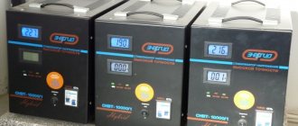
He who is forewarned is forearmed! To prevent expensive equipment from burning out due to another power surge, reliable protection is necessary. Voltage stabilizers are such protective devices. Below we have selected several models of single-phase stabilizers that are most suitable for both a private home and an apartment.
A voltage stabilizer is a complex device of an electromechanical or electrical type, the repair of which requires deep knowledge in the field of radio engineering, special tools and measuring equipment.
Voltage Stabilizer Error Codes
In addition to the faults described above, there are others that the device itself can help identify. If any problem occurs, a special signal containing the error code that occurred is displayed on the stabilizer display. Using this code, you can determine not only the nature of the malfunction, but how to eliminate it.
Let's look at the types of errors in voltage stabilizers using the example of a second-generation RUCELF electronic device. It is used to power household equipment, lighting systems, pumping, ventilation, air conditioning and navigation systems, electric welding and medical equipment, and office equipment.
| Error code | Description of the malfunction | Remedy |
| 01 | Incorrect start of work. | If, when turning on the power, it is not possible to set the output voltage to 220 volts, an error occurs. To restore the correct functioning of the device, you need to turn it off from the network and turn it on again after a short time. If the problem recurs, you should show the device to specialists. |
| 02 | Reduced output voltage. | Typically, normal operation is restored within five seconds after the output voltage is set above 190 volts. |
| 03 | Increased output voltage. | The situation is similar to the previous one. The output voltage should be set below 240 volts and the device should return to normal operation in no time. |
| 04 | Problems with the temperature sensor and/or temperature rise to 100 degrees or higher. | To disable the triggered protection, it is necessary to reduce the temperature to 55 degrees. |
| 05 | Voltage stabilizer current overload. | In this situation, the load should be reduced. To do this, set the output current level below 100% of its rated value. The protection will reset within five seconds. |
| 06 | Critical excess voltage at the input (above 300 volts). | If the voltage exceeds 300 volts for ten seconds, the protection is activated and the device automatically turns off. To resume normal operation, turn on the device again. |
| 07 | Temperature sensor malfunction. | An error blocks the operation of the stabilizer. To restore functionality, you must return the device to a service center. Most likely, the temperature sensor will need to be replaced. |
| 08 | Engine malfunction. | If the input voltage is between 140 and 260 volts for ten seconds, the device may not set the output voltage to an adequate (220 volt) voltage. In such a situation, the operation of the stabilizer is blocked and its engine will need to be repaired or replaced. |
| 09 | Critical error. | The operation of the device is blocked if the current protection is triggered three times within sixty minutes. To resume normal operation of the device, the automatic input voltage suppressor must be activated. |
The degree of difficulty of repairing various types of stabilizers
All devices are equipped with protection systems that determine the levels of input and output operating parameters to ensure their compliance with the nominal value. To carry out repair work, you must have measuring instruments, including an oscilloscope, and a circuit diagram of the device. It is necessary to measure the input and output voltage, the temperature conditions of the working units, exclude a short circuit, then look at the error code. The most difficult thing to diagnose is a failure in stabilizers equipped with triac switches - they are controlled by complex electronics. Measurements using an oscilloscope make it possible to identify a breakdown of a structural module, after which it is necessary to troubleshoot each radio component.
In relay-type devices, the relay that performs the function of switching the transformer windings most often fails. Due to frequent switching, the coil may jam or burn out, so if it breaks, it is necessary to check the functionality of all relays.
The simplest is to repair the electromechanical stabilizer - to see its reaction to changes in network parameters, just remove the housing. High precision and simplicity of design have made this type one of the most popular.
Stabilizer transformer overheating
If the transformer heats up without visible loads, there is most likely an interturn short circuit. However, the reason may also be due to broken switches.
In relay devices, the cause of overheating may be a jammed relay; in triac devices, one of the switches may break and short-circuit the output windings. In servo-drive stabilizers, there is no winding switching, but the brushes can short-circuit due to contamination - graphite filings or soot getting into the space between them. Servo-driven models require periodic cleaning of contact surfaces.
Repair and modification of servo stabilizers
The wear rate of the servo drive device and its contamination depend on two factors: room humidity and dust in the environment in which it is operated. To protect it from dust getting inside, the technician installs a computer cooler opposite the most used sector of the autotransformer. In addition to cleaning dust, the cooler performs the function of cooling the autotransformer.
Long-term storage of the stabilizer in a humid environment can lead to oxidation of the contact pads, which can interfere with the performance of the contact slider - dust can begin to spark and ignite.
Resanta ASN-500/1-C Operating instructions online [7/12]
During operation of the stabilizer, the following may appear on the display:
L - this means that the voltage in the network has dropped below the range
operation of the stabilizer (below 140 V) and the low voltage protection has tripped
voltage, the stabilizer continues to function and supply
voltage to the output, but the letter “L” is lit on the display. When voltage returns
the output voltage will return to the operating range.
– this means that the voltage in the network has risen above the operating voltage
range of the stabilizer (above 260 V) and protection against
overvoltage, the stabilizer turned off the output voltage to
avoid damage to the device. The stabilizer will automatically return to
operating state when the input voltage returns to the operating range.
– this means that the total power connected to
stabilizer of devices above the rated power of the stabilizer and
The thermal protection against overheating has tripped. It is necessary to reduce the load
(disconnect one or more consumers). After return
stabilizer into operating thermal mode, stabilizer automatically
1. Ambient temperature +5
2. The environment is non-explosive and does not contain conductive materials.
dust, aggressive gases, etc.
3. The minimum distance from the device body to the walls is 50 cm.
4. Avoid direct sunlight.
5. This stabilizer must be grounded.
6. This stabilizer must be used on a horizontal
STORAGE AND TRANSPORTATION RULES
The stabilizer must be stored in the container of the manufacturer at
The storage room should be free of dust, acid and alkali vapors.
Transportation of products in the manufacturer's packaging can be carried out
by any type of transport at any distance.
Transportation by air must be carried out in
During transportation, the packaging must be protected from direct
Do not tilt during transportation.
Stages of repair of a servo stabilizer
When starting repairs, remove the contact slider from the servo drive shaft. Then the contact surfaces are cleaned until the metal shines using sandpaper. Finish polishing is performed using an eraser. Abrasive particles and debris are removed using a brush.
After this, they move on to inspecting the graphite brush. It may fail due to excessive heating resulting from its poor contact with the autotransformer plates. When moving the slider, sparking and increased heating lead to burnout, which, in turn, further contaminates the contact pads and the space between them. This situation contributes to an increase in contamination, which leads to burnout of the brush and complete failure of the transformer - it stops producing voltage. In Resanta devices, if the output voltage is interrupted, protection is triggered.
Repair of Resanta stabilizers most often consists of cleaning the contact areas and replacing brushes.
Sometimes the servo drive breaks down, which can be caused by:
- engine burning;
- gearbox wear;
- no tension.
You can check this mechanism by removing the motor along with the gearbox and turning the shaft by hand. Residents of Odessa will be able to quickly and efficiently repair any type of stabilizer at the 24Master service.
Features of Resanta brand devices
It is not recommended to connect Resanta brand stabilizers to precision electronics, medical equipment, computers and LCD TVs. The reason for this is simple: in the event of a power surge in the network, the device’s protection will simply turn it off, and the output voltage may disappear for a short period of time, which can affect the operation of the equipment.
The advantages of Resanta devices include:
- high accuracy;
- performance;
- almost silent operation.
They are great for providing stable voltage in small factories and country houses - they can be connected to heating appliances, power tools, pumps, and automatic lines.
The machine is not working correctly
It takes a certain period of time for the voltage stabilizer to enter the operating state. It varies depending on the model.
If, after the return report, startup does not occur, and an “H” type error is displayed on the device monitor, then the device should be diagnosed.
In most cases, the problem is related to too high voltage in the electrical network. Otherwise, that is, with low readings, the letter “L” will be visible on the screen.
Also, the cause of the circuit breaker tripping may be a faulty relay.