As you already know from previous posts, we have a DIY movement in our company. In their free time, colleagues mill PCBs at home, make a thermal imager using a FLIR Lepton, and also resolve family disagreements with the help of 4 controllers and 2 smart watches. Let's continue the series of exciting stories! Today I will tell you how to make a controller for a three-phase electric bicycle motor with your own hands. The purpose of creating such a controller was:
- Studying the operation of a three-phase motor under the control of a controller.
- Most of the e-bike controllers on the market are Chinese. Although they are relatively cheap (about 2,000 rubles depending on the power), they are an unknown box in which it is not known what is happening. And immediately a lot of questions arise for it - whether it consumes and distributes current economically, what power reserve it has, why it overheats so much, why the current protection is triggered prematurely, etc.
At the same time, European high-quality controllers for electric bikes are presented on the market. They come with advanced features, operate at different voltages and currents, and are programmable. They are installed on heavy-duty electric bicycles. But their price is steep - 10-20 thousand rubles.
In the end, I decided to go my own way: understand the controller design, make a prototype, and then try to make the controller better than the Chinese controller. At the moment, my project is in development only at the prototype level; there is no ready-made version yet. I will be glad to hear your comments and advice.
Usage
There are a number of recommendations for the correct use of an angle grinder with an electronic unit.
When starting the tool, let it accelerate to the set speed, do not rush to cut anything. After turning off, restart it after a few seconds so that the capacitors in the circuit have time to discharge, then the restart will be smooth. You can adjust the speed while the grinder is operating by slowly turning the variable resistor knob. The good thing about a grinder without a speed controller is that without serious expenses you can make a universal speed controller for any power tool yourself. The electronic unit, mounted in a separate box, and not in the body of the grinding machine, can be used for a drill, drill, or circular saw. For any tool with a commutator motor. Of course, it’s more convenient when the control knob is on the instrument, and you don’t have to go anywhere or bend over to turn it. But here it’s up to you to decide. It's a matter of taste.
If you have an old grinder among your tools, do not rush to get rid of it. Using a simple electrical circuit, the tool can be improved by adding the option of adjusting the rotation speed. Thanks to a conventional control device, which you can create with your own hands within a few hours, the functions of the tool will expand significantly. By reducing the number of rotations per unit of time, the angle grinder can be used as a sharpening and grinding unit for different types of materials. There will be additional opportunities for using auxiliary equipment and attachments.
Why control the speed of the disk?
If the grinder is used for cutting and cutting tiles and natural stone products, the high rotation speed of the tool literally kills the power tool. In addition, with such processing, small particles begin to crumble from the material. This significantly deteriorates the quality and appearance of the tiled or stone surface. If there is a function for selecting the required speed, processing proceeds without a hitch. And the electric tool itself is completely protected from damage.
When cutting tiles and stone products, the grinder operates at a very high rotation speed
Rotation speed is also important when working with metal products. For example, aluminum or tin blanks should be cut at minimum speed. But thick and hard metal, on the contrary, is processed at high speeds. Polishing and grinding work using an angle grinder cannot be performed effectively if the saw does not allow you to select the required speed. You will simply ruin the surface being treated. Try sanding wood or the paintwork of a car body at high speed and you will understand what we are talking about.
As you can see, modifications to the angle grinder make the device many times more functional. It becomes possible to work with any soft materials and delicate surfaces. And most importantly, the grinder becomes almost eternal. It will function for decades!
Subtleties of work
If the regulator is assembled correctly and configured, then turning on the tool will be convenient at low speeds, when there is no jerk. During operation, especially considering the increased danger of angle grinders, it is necessary to make sure that accidental impact on the regulator handle is impossible
This is especially important if the regulator is built into the cord, not far from the body of the grinder itself.
If before this the machine did not have a regulator, then you need to keep in mind that this regulator will tend to maintain speeds close to idle under load, so there is no need to particularly accelerate the angle grinder under a heavy load. When the resistance of the material being processed brakes the disc, the voltage at the current sensor increases due to the increase in current, and the voltage at the motor drops slightly. The microcircuit reacts to this by changing the angle (the moment of unlocking the triac) in the direction of increasing power.
If the current is too high, the protection is triggered and the angle changes in the direction of decreasing power. So you may have to select R9 through experimentation, changing the calculated resistance within small limits.
Parts of electric motor rotation controllers
In these circuits, it is possible to use the following replacements of radio components: transistor KT817B - KT815, KT805; KT117A can be replaced with KT117B-G or 2N2646; Operational amplifier K140UD7 on K140UD6, KR544UD1, TL071, TL081; timer NE555 - S555, KR1006VI1; microcircuit TL074 - TL064, TL084, LM324.
When using a more powerful load, the KT817 key transistor can be replaced with a powerful field-effect transistor, for example, IRF3905 or similar.
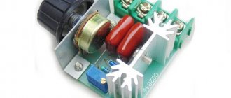
Based on the powerful triac BT138-600, you can assemble a circuit for an AC motor speed controller. This circuit is designed to regulate the rotation speed of electric motors of drilling machines, fans, vacuum cleaners, grinders, etc. The motor speed can be adjusted by changing the resistance of potentiometer P1. Parameter P1 determines the phase of the trigger pulse, which opens the triac. The circuit also performs a stabilization function, which maintains engine speed even under heavy load.
For example, when the motor of a drilling machine slows down due to increased metal resistance, the EMF of the motor also decreases. This leads to an increase in voltage in R2-P1 and C3 causing the triac to open for a longer time, and the speed increases accordingly.
Principle of operation
For assembly, it is best to choose a thyristor converter; it will allow you to change the operating mode without significant losses.
In addition, thanks to it, functions such as:
- Acceleration-braking.
- Tight control of characteristics.
- Switching to reverse movement.
In addition, it has pulse-phase control. Which allows you not to lose rotor torque without increasing losses in the reactive characteristic.
The speed controller circuit will consist of the following key components:
- Controlled signal rectifier.
- Control unit.
- Feedback system.
- Network power regulator.
How to connect the device to an angle grinder, options
The connection of the regulator depends on what type of device is selected. If a simple circuit is used, it is enough to mount it into the power supply channel of the power tool.
Installing a homemade board
There are no ready-made installation recipes. Anyone who decides to equip an angle grinder with a regulator places it in accordance with their goals and model of the tool. Some people insert the device into the handle of the holder, others into a special additional box on the body.
In different models, the space inside the angle grinder body may be different. Some have enough free space to install a control unit. In others, you have to take it to the surface and attach it in a different way. But the trick is that, as a rule, there is always a certain cavity in the back of the instrument. It is designed for air circulation and cooling.
Cavity at the back of the device
This is usually where the factory speed controller is located. A DIY diagram can be placed in this space. To prevent the regulator from burning out, the thyristors should be installed on the radiator.
Features of installation of the finished block
When purchasing and installing a factory regulator inside an angle grinder, most often you have to modify the body - cut a hole in it to allow the adjustment wheel to come out. But this may adversely affect the rigidity of the casing. Therefore, it is preferable to install the device outside.
The adjustment wheel changes the speed
The numbers on the adjustment wheel indicate the number of spindle revolutions. This value is not absolute, but conditional. “1” is the minimum speed, “9” is the maximum. The remaining numbers serve as a guide for regulation. The location of the wheel on the body varies. For example, on the Bosch PWS 1300–125 CE, Wortex AG 1213–1 E or Watt WWS-900 angle grinders, it is located at the base of the handle. On other models, such as the Makita 9565 CVL, the adjustment wheel is located at the end of the housing.
The connection diagram of the regulator to the angle grinder is not complicated, but sometimes it is not so easy to stretch the cables to the button, which is located at the other end of the device body. The problem can be solved by selecting the optimal wire cross-section or by placing it on the surface of the casing.
The regulator is connected according to the diagram
A good option is to install the regulator on the surface of the device or attach it to a network cable. Not everything always works out on the first try; sometimes the device has to be tested and then some adjustments made. And this is easier to do when access to its elements is open.
Attaching to the power cord
Device Instruction Manual
The basic rule when operating an angle grinder with a homemade speed controller is to adhere to the work and rest schedule. The fact is that an engine operating at a “regulated” voltage gets especially hot
When grinding at low speeds, it is important to take frequent breaks so that the commutator windings do not burn out.
It is also highly recommended not to turn on the tool if the speed controller is set to minimum - the reduced voltage will not be enough to rotate the rotor, the collector lamellas will remain in short circuit mode, and the windings will begin to overheat. Unscrew the variable resistor to the maximum, then, turning on the angle grinder, reduce the speed to the desired value.
In addition, it should be understood that adjusting the speed of rotation on an angle grinder occurs on the principle of a water tap. The device does not increase the number of revolutions, it can only decrease them. It follows from this that if the maximum nameplate speed is 3000 rpm, then when a speed controller is connected, the angle grinder will operate in a range lower than the maximum speed.
Video: homemade angle grinder speed controller
Equipping the angle grinder with a circuit for adjusting engine speed will increase the efficiency of using the device. and expand its functional range. This will also save the technological resource of the grinding machine and increase its service life.
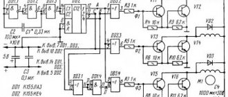
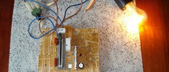
Typical speed controller circuit
This is what the assembled speed controller board looks like
The engine speed controller is not just a variable resistor that lowers the voltage. Electronic control of the current strength is necessary, otherwise, as the speed drops, the power and, accordingly, the torque will decrease proportionally. In the end, a critically low voltage value will occur when, even with the slightest resistance of the disk, the electric motor simply cannot turn the shaft. Therefore, even the simplest regulator must be calculated and implemented in the form of a well-developed circuit.
And more advanced (and therefore expensive) models are equipped with regulators based on an integrated circuit.
Integrated controller circuit. (the most advanced option)
If we consider the electrical circuit of the angle grinder in principle, it consists of a speed controller and a soft start module. Power tools equipped with advanced electronic systems are significantly more expensive than their simpler counterparts. Therefore, not every home craftsman is able to purchase such a model. And without these electronic units, all that remains is the electric motor winding and the power button.
The reliability of modern electronic components of angle grinders exceeds the service life of motor windings, so you should not be afraid of purchasing a power tool equipped with such devices. The only limiting factor can be the price of the product. Moreover, users of inexpensive models without a regulator sooner or later come to install it themselves. The block can be purchased ready-made or made independently.
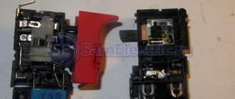
Transistors and H-bridge
But in order to alternately supply current to each of the phases and change their polarity, transistors are needed. We also need the transmission of high currents, high switching speeds and clear opening/closing of the gates. In this case, it is more convenient to control the gates by voltage rather than by current. Therefore, field-effect (MOSFET) transistors are optimal. Most often they are used in controllers. It is very rare to find a combined version of transistors.
To switch phases and change their polarities, use the classic H-Bridge circuit of field-effect transistors.
It consists of three pairs of transistors. Each pair is connected to the corresponding phase of the motor winding and supplies current with a value (+ or –). Transistors responsible for turning on the phase with a positive value are called upper switches. With negative ones - lower ones. For each step, a pair of keys is opened: the upper one of one phase and the lower one of the adjacent phase. As a result, current passes from one phase to another and drives the electric motor.
From the diagram it is clear that we cannot turn on the upper and lower switches at the same time at the same phase: a short circuit will occur. Therefore, it is very important to quickly switch the upper and lower keys so that a short circuit does not appear during transient processes. And the better and faster we provide switching, the less losses and heating/overheating of the H-bridge transistors we will have.
To start, it remains to control the gates of the H-bridge keys. To control the H-bridge you need:
- Read Hall sensor readings.
- Determine in what position which pair of keys should be turned on.
- Transmit signals to the corresponding gates of the transistors.
Why do you need to adjust the speed on an angle grinder?
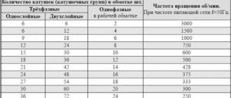
Any grinder is structurally “sharpened” to work only with a cutting or grinding wheel of a certain diameter. In total, there are six most common diameters in the range from 115 to 300 mm, which correspond to six groups of spindle rotation speeds at idle. For example, grinders with Ø125 mm wheels have a rotation speed of about 11÷12 thousand rpm, and with Ø150 mm wheels - 9÷10 thousand rpm. Such spindle speed values are due to the fact that cutting discs are designed for high-performance processing of hard materials (metal, stone, ceramics) at cutting speeds of up to 80 m/sec.
However, when cutting and especially grinding soft and viscous materials, completely different cutting parameters are required and, accordingly, the use of a tool with a speed controller. Moreover, this applies not only to wood and plastics, but also to steels, titanium and aluminum alloys. For example, processing of plastics and soft woods occurs at cutting speeds from 8 to 12 m/sec, grinding of titanium and stainless steel alloys - within 15÷20 m/sec, and even ordinary steel is ground at no more than 30 m/sec. Therefore, the rotation speed of grinding attachments for grinders should be several times less than the rated speed. It should be noted that for the most part, angle grinder speed controllers are essentially regulators of the power supplied to the electric motor of the angle grinder. That is, a reduction in the speed is achieved by reducing the source power by up to 15% of the nominal. But for grinding and cutting soft materials this does not matter much, since in this case little power is initially required.
Overview of typical circuits
You can regulate the rotation of the shaft of a low-power electric motor by connecting a power resistor in series with no. However, this option has very low efficiency and the inability to smoothly change speed. To avoid such a nuisance, you should consider several regulator circuits that are used most often.
As you know, PWM has a constant pulse amplitude. In addition, the amplitude is identical to the supply voltage. Consequently, the electric motor will not stop even when running at low speeds.
The second option is similar to the first. The only difference is that an operational amplifier is used as the master oscillator. This component has a frequency of 500 Hz and produces triangular-shaped pulses. Adjustment is also carried out using a variable resistor.
Speed controller and soft start - what are they for?
Modern grinders use two important functions that increase the reliability and safety of the tool:
- speed controller - a device designed to change the number of engine revolutions in various operating modes;
- soft start - a circuit that ensures a slow increase in engine speed from zero to maximum when the device is turned on.
They are used in electromechanical tools that use a commutator motor in their design. Helps reduce wear on the mechanical part of the unit during switching on. They reduce the load on the electrical elements of the mechanism by putting them into operation gradually.
When the power is turned on, an abrupt transition occurs from a state of rest to rotation of the disk at a speed of 2.5–10 thousand revolutions per minute. Those who have worked with an angle grinder are well aware of the feeling that the machine simply “rips out of your hands.” It is at this moment that the overwhelming number of breakdowns associated with the mechanical part of the unit occur.
The stator and rotor windings experience no less load. The commutator motor starts in short circuit mode, the electromotive force is already pushing the shaft forward, but inertia does not yet allow it to rotate. A jump in starting current occurs in the coils of the electric motor. And although they are structurally designed for such work, sooner or later a moment comes (for example, during a power surge in the network) when the winding insulation cannot withstand and an interturn short circuit occurs.
When soft start circuits and changes in engine speed are included in the electrical circuit of the tool, all of the above problems automatically disappear. Among other things, the problem of voltage “dip” in the general network at the moment of starting a hand tool is solved. This means that the refrigerator, TV or computer will not be at risk of “burning out”. And the safety circuit breakers on the meter will not operate and cut off the current in the house or apartment.
The soft start circuit is used in angle grinders of medium and high price categories, the speed control unit is used mainly in professional models of angle grinders.
Additional electrical circuits increase the cost of the tool, but increase the service life and level of safety during operation.
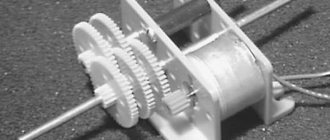
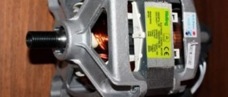
Engine device
To develop a controller, it is necessary to understand the operating principle of the electric motor itself.
The electric motor consists of phase windings, magnets and Hall sensors that monitor the position of the motor shaft.
Structurally, electric motors are divided into two types: inrunners and outrunners.
In inrunners, magnetic plates are attached to the shaft, and the windings are located on the drum (stator), in which case the shaft is driven. In the case of an outrunner, the opposite is true: there are phase windings on the shaft, and magnetic plates in the drum. This sets the drum in motion.
Since the wheel of a bicycle is attached by a shaft to the frame, the outrunner type is used here.
This picture conventionally shows three phases with windings connected to each other. In reality, there are much more windings; they are evenly spaced with alternating phases around the circumference of the motor. The more windings, the smoother, clearer, and more elastic the engine operates.
Three Hall sensors are installed in the engine. The sensors react to the magnetic field, thereby determining the position of the rotor relative to the motor stator. Installed at intervals of 60 or 120 electrical degrees. These degrees refer to the electrical phase rotation of the motor. It must be taken into account that the more windings per phase in the motor, the more electrical revolutions occur during one physical revolution of the motor-wheel.
Windings of three phases in most cases are connected to each other according to two circuits: star and triangle. In the first case, the current passes from one of the phases to the other, in the second - through all three phases to varying degrees. Sometimes these two connection schemes are combined in one engine, for example in electric vehicles. When starting and accelerating, the phases are connected according to a star: it gives more torque at relatively low speeds; then, after gaining speed, a switch to a triangle occurs, as a result, the number of revolutions increases when high torque is no longer needed. In essence, it turns out to be a conditionally automatic gearbox of an electric motor.
Photo of the speed controller with your own hands
Screwdriver speed controller
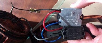
An electric screwdriver operates either from a 220 V network or from a rechargeable battery. Its power depends on the battery voltage. The screwdriver rotation speed starts at 15,000 rpm. In addition, a powered screwdriver has 2 rotation speeds: a slower one for screwing, a higher one for drilling. The speed control is located inside the power button. The rather miniature size of this tool assembly is achieved using microfilm technology. Its main part is a triac. The operating principle of the regulator is as follows:
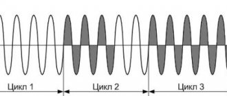
- When the button is turned on, an alternating current having a sinusoidal phase is supplied to the control electrode of the triac.
- The triac opens and current begins to pass through the load.
The response time of the triac depends on the amplitude of the control voltage. The greater the amplitude, the earlier the triac is triggered. The amplitude value is set using a variable resistor connected to the start button. The button connection diagram differs in different models. It is possible to connect a capacitor to the speed controller.
Often, in the current economic conditions, the buyer cannot always afford a full-fledged expensive screwdriver from reputable companies. Cheaper models may not have this feature. But this is no reason to despair. You can assemble the speed controller yourself, which we will talk about below.
The screwdriver speed controller is assembled on the basis of a PWM controller and a key multi-channel field-effect transistor. The operation of this tool unit is controlled by a resistor. Its position depends on the pressure on the screwdriver start button.
The direction of rotation of the working body changes by changing the poles of the voltage that is supplied to the motor brushes. This is done instrumentally using changeover contacts actuated by a reverse lever.
It is possible to assemble such a regulator with your own hands. We will look at how to do this below.
A diagram of the elements that make up the speed controller is shown in the figure below.
Scheme
In this case, a dual comparator microcircuit LM 393 is used. Here, the first comparator works as a sawtooth voltage generator, and the second one is PWM. The control signal for PWM is the voltage drop across the motor contacts. To put it simply, in the diagram the electric motor looks like active and inductive resistances connected in series with each other. When the load changes, the ratio of these resistances changes accordingly, the regulator controls this and changes the PWM filling, thereby stabilizing the speed.
An electronic transformer should be used as the power source for PWM. It is a half-bridge voltage converter from 220 to 12 V, which is used to power halogen lighting lamps. Its dimensions are comparable to the size of a matchbox. The price fluctuates between 2–3 USD. e. It is necessary to add a rectifier to the output (these are four diodes, for example, KD 213), as well as a capacitor with a capacity of several thousand microfarads at 25 volts. All this will constitute a switching power supply with a constant output voltage.
We should also talk about making a printed circuit board for the regulator. To make it you need a sheet of photo paper and a laser printer. First you need to print the design on photo paper using a laser printer, then transfer it to the board blank using a heated iron. The board blank with the paper attached is placed in a container and placed under a stream of hot water. This is done so that the gelatin layer of the photo paper swells and it peels off from the board. The remaining pattern on the board is etched with ferric chloride.
Adjustment
Now let's talk about how you can regulate the speed of commutator motors. Due to the fact that the rotation speed of the motor simply depends on the amount of voltage supplied, any means of adjustment that are capable of performing this function are quite suitable for this.
Let's list a few of these options as examples:
- Laboratory autotransformer (LATR).
- Factory control boards used in household appliances (you can use, in particular, those used in mixers or vacuum cleaners).
- Buttons used in the design of power tools.
- Household lighting regulators with smooth action.
Read also: Landing diameters of saw blades
However, all of the above methods have a very important flaw. Along with the decrease in speed, the engine power also decreases. In some cases, it can be stopped even just with your hand. In some cases, this may be acceptable, but in most cases, it is a serious obstacle.
A good option is to adjust the speed using a tachogenerator. It is usually installed at the factory. If there are deviations in the motor rotation speed, an already adjusted power supply corresponding to the required rotation speed is transmitted through the triacs to the motor. If you integrate motor rotation control into this circuit, then there will be no loss of power.
How does this look constructively? The most common are rheostatic rotation control, and those made using semiconductors.
In the first case, we are talking about variable resistance with mechanical adjustment. It is connected in series to the commutator motor. The disadvantage is the additional heat generation and additional waste of battery life. With this adjustment method, there is a loss of engine rotation power. Is a cheap solution. Not applicable for sufficiently powerful motors for the reasons mentioned.
In the second case, when using semiconductors, the motor is controlled by applying certain pulses. The circuit can change the duration of such pulses, which in turn changes the rotation speed without loss of power.
Creating a regulator yourself
How to make your own regulator? The attempt to install an ordinary electronic device designed to change electrical power (dimmer) ends in nothing. First of all, the dimmer for an angle grinder is designed for a different load. Also, the dimmer is not combined with the control of the electric motor winding. Therefore, it is necessary to install a separate circuit. You also need to figure out where it will be located inside the body of the angle grinder.
You can build a simple semiconductor device (thyristor regulator) with your own hands. For this procedure you will need 5 radioelements. Radio elements can be bought on the radio market. Thanks to its compactness, you can safely place the prepared circuit in an angle grinder without damaging ergonomics and reliability. However, torque conservation does not occur when the speed of the grinder is reduced. This option is best suited for processing soft metals, as well as thin sheet metal.
If you are processing stone, then you need to install a disk that has a size of 180 millimeters. Next you need to create a more complicated regulator circuit. In this circuit, the control module will be the KR1182PM1 microcircuit. This circuit has control over the current strength at different speeds, and also makes the loss of torque minimal as the speed decreases. When using this scheme, engine operation increases.
If the angle grinder is used as a circular grinder, then you need to equip the angle grinder with a connection point. Thanks to this point, the connection is made, and the speed can be adjusted remotely. You will have an excellent homemade speed controller.
It does not depend on how you made the regulator, but it is an essential component of an angle grinder, which makes the work possibilities wider and allows you to comfortably use this construction tool. Also, after installing the regulator, it is necessary to conduct a test run of the angle grinder to check whether the construction tool is pulled out of your hands. You can make an external speed controller for an angle grinder yourself.
Selection criteria and cost
In order to correctly choose the most suitable type of regulator, you need to have a good idea of what types of such devices there are:
- Various types of control. Can be a vector or scalar control system. The former are used more often, while the latter are considered more reliable.
- The power of the regulator must correspond to the maximum possible power of the motor.
- Based on voltage, it is convenient to choose a device that has the most universal properties.
- Frequency characteristics. The regulator that suits you should match the highest frequency that the motor uses.
- Other characteristics. Here we are talking about the length of the warranty period, dimensions and other characteristics.
Depending on the purpose and consumer properties, prices for regulators can vary significantly.
For the most part, they range from approximately 3.5 thousand rubles to 9 thousand:
- Speed controller KA-18 ESC , designed for 1:10 scale models. Costs 6890 rubles.
- MEGA speed controller is manifold (waterproof). Costs 3605 rubles.
- Speed controller for LaTrax 1:18 models. Its price is 5690 rubles.
This DIY circuit can be used as a speed controller for a 12V DC motor with a current rating of up to 5A, or as a dimmer for 12V halogen and LED lamps up to 50W. Control is carried out using pulse width modulation (PWM) at a pulse repetition rate of about 200 Hz. Naturally, the frequency can be changed if necessary, selecting for maximum stability and efficiency.