Designed to protect people working on disconnected live parts of equipment or electrical installations from electric shock in the event of an erroneous supply of voltage to the disconnected area or when induced voltage appears on it. Portable grounding is used in those parts of the electrical installation that do not have stationary grounding blades.
The protective effect of portable grounding or stationary grounding blades is that they do not allow voltage to appear beyond the place of their installation. When voltage is applied to a grounded and shorted section, a short circuit occurs. Thanks to this, the voltage at the point of the short circuit is reduced to almost zero and no voltage will flow to the current-carrying parts behind the grounding. In addition, the protection will work and turn off the voltage source.
The lack of installed portable grounding on live parts of the electrical installation being serviced, violation of the regulations for their use, the use of low-quality grounding or that does not comply with current technical standards have repeatedly led to severe, including fatal, electrical injuries.
What is portable grounding and its purpose
Portable grounding (PG) is a special product designed for grounding individual sections of an electrical installation that do not have stationary grounding blades. The main function of the PP is to ensure the safety of workers when carrying out repair work.
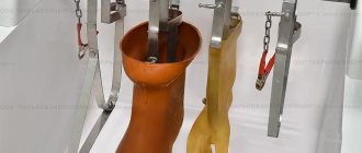
This is what portable grounding looks like
Installing a PZ allows you to protect personnel from exposure to electric current due to erroneous, spontaneous supply of voltage, as well as as a result of the formation of induced voltage. When voltage is applied to a grounded section of the electrical network, a short circuit current is generated, which leads to the launch of protection, followed by disconnection of the voltage source.
How to maintain a normal frequency of checking equipment grounding?
To completely eliminate problems associated with the operation of the installation, you need to use the services of an electrical laboratory. Thanks to this, the logbook for checking the grounding of electrical equipment will always be completed within the required time frame, as well as in compliance with the basic existing requirements. It is also worth noting the possibility of issuing protocols, without which it is impossible to obtain permits.
Our company can provide you with advice on all issues, including the frequency of checking equipment grounding, as well as the methodology for performing this type of work. Plus, we guarantee extremely accurate results that will truly tell you whether your installation is safe, not just help you bypass the bureaucratic hurdles of obtaining permits.
Example of a technical report for non-residential premises
Back
Forward
Below you can use the online calculator to calculate the cost of electrical laboratory services.
Device
There are two main options for using PP. The first option is intended for use in switchgears, and the second - on overhead power lines. Grounding can be made in single-phase or three-phase design.
The PZ can be made in three design variations: rod, rod with a metal link (ZPL-10) and rodless (ZPP-15).
Portable grounding type ZLP-10
The design of the product consists of the following elements:
- flexible conductor (copper or aluminum);
- fastening clips;
- tips (clamps);
- dielectric rod.
The rodless design of the PZ is usually used for use in complete switchgears.
Example of a rodless PZ design
To simultaneously short-circuit three phases through a single grounding conductor, a three-phase grounding conductor is used.
Single-phase version of portable grounding is intended for separate connection of phases to the grounding loop. Used on power lines with a voltage level of more than 110 kV. This is due to the significant distance from the grounding bus to the phase wires and the phase-to-phase span.
The flexible conductor may be coated with transparent insulation. It can be made of aluminum or copper wires. Using clamps, the PZ is attached to live parts and to the ground loop. The device of phase clamps can be made in the form of clamps and copper tips. The clamps are tightened using an insulating rod, with the help of which the minimum permissible distance to live parts is achieved.
Alphanumeric designations
GOST specifies regulations for marking the external insulation of cable lines, thanks to which cords, cables and wires can be distinguished from each other. If there are no markings on the braid or they are not sufficient for maintenance and safety, then special tags with additional data are attached to the route.
According to the rules and recommendations prescribed in GOST, a wire is a product consisting of one or more cores, which are protected with insulation along their entire length. The cores can be produced without insulation. A cable is defined as several conductors insulated separately from each other, placed under a single sealed sheath made of metal or polymer materials. A cord consists of two or more flexible conductors that are connected together by twisting or braiding. The cores are fixed along their entire length, and the braid is made from non-metallic materials.
Requirements
There are many requirements for portable grounding systems. Among the main ones, thermal and dynamic stability with respect to short circuit currents stands out. The design of products should ensure ease of use.
The shorting conductors must withstand environmental influences ranging from -45 to +45 degrees. The cross-sections of the grounding conductors must correspond to the voltage levels. In electrical installations up to 1 kV, 16 square millimeters are used, and at voltages above 1 kV - 25. At a voltage level of more than six kilovolts, the cross-section of the conductors can reach one hundred and twenty square millimeters.
If there are different voltage levels in electrical installations, it is permitted to use portable grounding with the largest required cross-section to service all electrical equipment.
The product package must include technical documentation. The clamp can be fastened to the conductor cores by bolting, welding, pressing or using pressure plates. The clamp must ensure reliable contact at the application site. Insulating structures must be made of dielectric materials.
It is prohibited to use protective shells on conductive elements of the ground electrode, which interfere with visual inspection of their integrity. To insulate wires, it is allowed to use only a transparent sheath.
Marker fastening
Cable tags can be attached to wires using various fasteners. The most common are synthetic thread, plastic tapes with a latch, wire with an anti-corrosion coating, clips, etc. If you need to use ordinary steel wire for fastening, then it should first be coated with a protective layer of bitumen or paint to prevent corrosion. Ideally, you should use polyvinyl chloride insulated wire.
Calculation of cross-section for PZ
The minimum cross-section of the grounding conductor is determined by the formula:
Smin = (Ik.z.*√t)/C
- I short circuit – maximum current value during a short circuit;
- √t – the longest response time of the main protective devices to disconnect a short circuit;
- C is the calculated coefficient, which reflects the change in the resistance of the material under the influence of heat.
The longest time to disconnect a short circuit is taken to be the total value of the following indicators:
- activation time of the main protection;
- response time of automatic restart (reclose);
- duration of machine shutdown.
The calculated value of I short circuit depends on the type of neutral of the electrical network. With a grounded neutral, the value of single-phase short circuit current is used, with an isolated neutral - three-phase.
Installation and removal of portable grounding
The process of applying and removing grounding is identical for all voltage levels. There are differences only in the number of people performing these operations. In electrical installations up to 1 kV, installation and removal of the ground electrode is carried out individually, and at voltages above 1 kV, the procedure is performed by two people. One person acts as a controller, and the second is an executor.
Process of installation and installation of PZ
Sequence of actions when installing the software:
- Make sure the integrity of the installed grounding;
- Check that there is no voltage at the electrical installation that must be grounded;
- Connect the clamp PZ to the ground loop;
- Place grounding conductors on current-carrying elements.
Operations for removing portable grounding are carried out in the reverse order. All actions must be carried out using dielectric gloves and rods, as well as personal protective equipment. In electrical installations up to 1 kV, only insulating gloves may be used. When the voltage of current-carrying elements is more than 1000 V, the simultaneous use of gloves and rods is required.
Checking the absence of voltage in a section of the distribution installation is carried out with a voltage indicator.
Parallel installation of portable ground electrodes in an electrical network with a voltage of more than six thousand volts is allowed. This is due to the fact that the required wire cross-sections reach significant values. And it leads to an increase in the mass and size of the PZ, which entails difficulties in their operation.
Increased security
The procedure for installing any portable grounding used in electrical installations requires the mandatory application of efforts to increase the level of safety of working personnel. Timely adoption of all necessary measures reduces to zero the likelihood of accidental supply of dangerous voltage to sections of the line where repair work is being carried out. To this end, the following mandatory actions will need to be taken:
The doors of the switching equipment, through which voltage from the cable input is supplied to this section of the electrical network, are securely locked. Special insulating caps are placed on the contacts of the knife blocks of the switches that supply voltage to the operating network. Warning posters such as “Work on the line” or “Caution - people are working” are posted on the keys of switching devices.
Posters posted on circuit breakers “Do not turn on, work on line”
Knowledge of the main provisions of this document must be checked during the briefing conducted with members of the installation team before the start of restoration work on the power line.
Each member of the electrical installation team must know in what cases and how he is obliged to act in the event of a threat of electric shock. The person who authorizes the team to work has the right to demand from each of its members knowledge of the rules for providing first aid to a victim of an electric shock. In addition, in particularly dangerous areas, in addition to the person responsible for the work, an observer from among the operational personnel is appointed. Its function is to monitor the order of work operations and issue instructions on violations committed during their implementation.
When removing and applying portable grounding, the employee must strictly follow the above procedure. Even if voltage is mistakenly supplied to the network, the worker will not receive an electric shock when the grounding cable clamp is connected.
Tests
To confirm compliance with GOST requirements, portable grounding systems are subjected to the following types of tests:
- acceptance (during the initial check for compliance with established standards);
- periodic (permissible once every five years);
- standard (with design changes).
Portable groundings are considered suitable for use if the following measures are successfully completed:
1. Visual inspection of the integrity of all structural elements.
Includes inspection of clamps, conductor cores, insulating rod, restrictive ring on the rod, anti-corrosion coating, protective insulation and technical documentation.
2. Climatic tests.
The procedure is carried out at negative and positive temperatures. Its value should reach forty-five degrees Celsius, respectively, below and above zero. Portable grounding is exposed to temperature for two hours. If there are no signs of destruction of the protective insulation and plastic elements, the product is considered suitable for use.
3. Determination of the mechanical strength of rods.
This experiment is intended to measure the bending of the PZ rod. The permissible deflection deviation is ten percent relative to the insulating length of the rod used for electrical installations with voltages up to 220 kV. For higher voltage levels, a twenty percent deviation is allowed.
To carry out the test, the rod is fixed in a horizontal plane. Securing the end of the rod and the place where the restrictive ring fits. Use a metal ruler to set the level of the rod axis. And according to it, the amount of deflection is calculated.
4. Checking the cross-section of the cores.
To establish the actual cross-section of the portable grounding, it is disassembled into strands. Their number is recorded and the number of conductors in one strand is counted. The diameter of the conductor is measured to determine its cross-section. The resulting calculated value is multiplied by the number of conductors in the strand and by the number of strands.
5. Measurement of thermal and dynamic resistance.
The experiment consists of passing through the finished product the appropriate value of short circuit current from laboratory current sources. The current flow continues until the prototype is completely destroyed. If within three seconds no mechanical damage or cores being thrown from the installation sites were observed, then the sample satisfies thermal and dynamic resistance.
6. Determination of the level of contact resistance.
A microohmmeter is used to measure the resistance at the point where the conductors are connected to the clamp. This indicator should not exceed 600 μOhm.
7. Electrical checks of insulating elements.
The insulating parts of portable grounding are subjected to high-voltage tests.
During operation, mechanical tests of grounding wires are not performed. Rods with metal elements are subject to electrical testing. This procedure is performed every two years.
The product is removed from service if the following defects are found:
- disruption of the connection between the clamp and the conductor;
- traces of metal melting or destruction of grounding conductors;
- the presence of more than five percent breakage of conductor cores.
Resistance value
The resistance that grounding provides is the ability of the soil to distribute the electric current that enters it with the help of grounding electrodes. The size is important for portable and stationary devices. It is measured in ohms and depends directly on the soil resistance and the area of contact between the ground electrode and the ground. You can change the area by increasing the depth of the electrode or connecting several short electrodes together. In the latter case, the cross-sectional area increases.
The lower the indicator, the better the work with it. A zero value cannot be achieved under natural conditions, so most often different types of electrical equipment have different norms - from 60 to 0.5 Ohms.
If the grounding connection occurs through the neutral of the transformer, the total resistance should not exceed 4 Ohms. Otherwise, the meaning of its use is lost. If it is necessary to arrange grounding in a private house, the calculation should be based on the fact that in such houses the value does not exceed 30 Ohms.
If you need to install grounding to connect an air terminal, changing the cross-section and length, you should achieve a resistance of no more than 10 Ohms. When grounded, a current source in the form of a transformer or generator should not be connected to surfaces with a resistance exceeding 8 ohms. The permissible value directly depends on the voltage. If the voltage in the transformer is 380, the resistance should be no more than 2 ohms, 220 - no more than 4 ohms, 127 - no more than 8 ohms.
If the equipment is equipped with gas arresters used to protect lines carried through the air, the grounding should not produce a resistance greater than 2 ohms; some equipment allows 4 ohms and has special notes about this.
For telecommunications equipment, the resistance requirements are 2-4 ohms. If a substation designed for 110 kV is used, the grounding resistance should not be higher than 0.5 Ohm.
The resistance standards illustrated above apply to normal soils, the resistivity of which is not higher than 100 Ohm*m. These soils include clayey and loamy soils. For example, sandy surfaces are characterized by a resistivity of 500 Ohm*m, which exceeds the well-known and generally accepted standard by five times.
Equipment and markings
Depending on the design of the product, the kit includes:
- portable grounding, assembled or disassembled;
- insulating rods;
- covers;
- technical certificate.
All portable grounding connections must be marked. Which reflects the following information:
- trademark or name of the enterprise that produced the PZ;
- release date and product type;
- core section;
- operating voltage level.