Owners of hand-held power tools, both amateurs and professionals, often encounter breakdowns. This is not always the user's fault. There are features due to which this happens regardless of external factors. It depends on the technical perfection of the product, its price and scope of application. A significant portion of malfunctions can be avoided even when using inexpensive power tools if you perform simple modifications, for example, making a soft start.
General information
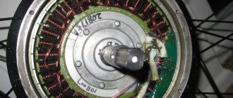
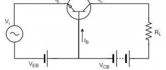
The stator of an electric motor is an inductance coil; therefore, there are resistances with an active and reactive component.
When electric current flows through radioelements that have resistance with an active component, losses occur due to the conversion of part of the power into thermal energy. For example, a resistor and the stator windings of an electric motor have a resistance with an active component. Calculating active resistance is not difficult, since the phases of the current (I) and voltage (U) coincide. Using Ohm's law for a section of a circuit, you can calculate the active resistance: R = U/I. It depends on the material, cross-sectional area, length and its temperature.
If the current passes through a reactive type of element (with capacitive and inductive characteristics), then, in this case, a reactive R appears. An inductor that has practically no active resistance (the calculations do not take into account the R of its windings). This type of R is created due to the Electromotive Force (EMF) of self-induction, which is directly proportional to the inductance and frequency I passing through its turns: Xl = wL, where w is the angular frequency of the alternating current (w = 2*Pi*f, and f - network current frequency) and L - inductance (L = n * n / Rm, n - number of turns and Rm - magnetic resistance).
When the electric motor is turned on, the starting current is 7 times greater than the rated current (the current consumed during operation of the tool) and the stator windings heat up. If the stator coil is old, then an interturn short circuit may occur, which will lead to failure of the power tool. To do this, you need to use a soft starter for a power tool.
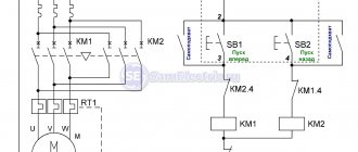
One of the methods for reducing the inrush current (Ip) is to switch windings. To implement it, 2 types of relays (time and load) and the presence of three contactors are required.
Starting an electric motor with windings connected in a star type is possible only with 2 contactors not simultaneously closed. After a certain time interval, which is set by a time relay, one of the contactors is turned off and another one, not previously used, is turned on. Thanks to this alternation of switching on the windings, the inrush current decreases. This method has a significant drawback, since when two contactors are simultaneously closed, a short-circuit current occurs. However, when using this method, the windings continue to heat up.
Soft starters with three wires
By the way, be careful, there are similar devices, but with three wires. For example XS-12/D3.
Or other models that look similar to KRRQD.
But they are assembled on a slightly different principle and need to be installed after the START button, in the instrument itself. Voltage should be applied to them only at the moment the grinder's start button is closed and immediately disappear after it is released.
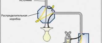
The connection diagram for them is as follows:
The phase is supplied to contact “A”, zero to “C”. Next, the phase with the output control wire goes to the engine (this is exactly the third wire).
Without a button, such a device will be constantly powered by 220V, which is not acceptable.
There is no such thing in a two-wire unit, since it is connected to an open circuit, and voltage (potential difference) is applied to it only at the moment of starting and operating the tool.
Another point is the so-called electric brake or brake winding on the crosscuts. It may not work with a 3-wire external soft starter, but it will work with a 2-wire model.
Operating principle
During the start-up of a commutator-type electric motor, a significant short-term increase in current consumption occurs, which causes premature failure of the power tool and requires it to be repaired. Electrical parts wear out (current exceeds 7 times) and mechanical parts (sharp start). To organize a “soft” start, soft start devices (hereinafter referred to as soft starters) should be used. These devices must meet the basic requirements:
- Smooth increase in load.
- Possibility of starting the engine at certain time intervals.
- Providing protection against linear surges of U, phase loss (for a 3-phase electric motor) and various interference of the electrical component.
- Significantly increased service life.
The most widely used are triac soft starters, the operating principle of which is smooth regulation of U by adjusting the opening angle of the triac junction. The triac must be connected directly to the motor windings and this allows you to reduce the starting current from 2 to 5 times (depending on the triac and control circuit). The main disadvantages of triac soft starters are the following:
- Complex schemes.
- Overheating of windings during prolonged startup.
- Problems with starting the engine (leads to significant heating of the stator windings).
The circuits become more complicated when using powerful engines, however, with light loads and idle speed, simple circuits can be used.
Soft starters with regulators without feedback (1 or 3 phases) have become widespread. In models of this type, it becomes possible to pre-set the start time and U value before starting the engine. However, in this case it is impossible to regulate the amount of torque under load. With this model, a special device is used to reduce the starting current, protect against phase loss and imbalance, as well as against overloads. Factory models have a function for monitoring the condition of the electric motor.
The simplest single-phase control circuits are executed on a single triac and are used for instruments with a power of up to 12 kW. There are more complex circuits that allow you to adjust the power parameters of an engine with a power of up to 260 kW. When choosing a factory-made soft starter, it is necessary to take into account the following parameters: power, possible operating modes, equality of permissible currents and the number of starts in a certain period of time.
Collection of circuit diagrams
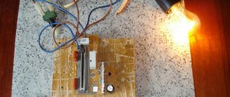
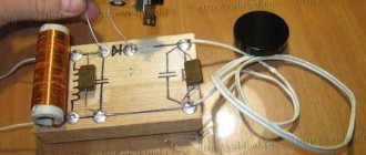
First there are well-known schemes from the Internet, and then a few collected in person and working perfectly. The first circuit is the simplest - when power is applied, the diode gradually increases brightness (the transistor opens as the capacitor charges):
I made this circuit for smoothly turning on and off the LEDs; resistor R7 selects the required current through the diode. And if you connect this breaker instead of a button, then the circuit itself will light up and die out, only you need to set the desired time interval with resistor R3.
Here are two more schemes for smooth ignition and decay, which I also personally soldered:
All these designs are not network (from 220 V), but ordinary low-voltage LED indicators. Industrial LED lamps with their unknown drivers, most often in different smooth controllers, work unpredictably (or blink, or turn on abruptly). So you need to control not the drivers, but the LEDs directly. Schemes provided by senya70.
Discuss the article SOFT ON/OFF OF LEDS
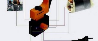
Application in an angle grinder
When starting an angle grinder (angle grinder), high dynamic loads appear on the tool parts.
Expensive models are equipped with soft starters, but not ordinary varieties, for example, angle grinders. An inertial jerk can tear an angle grinder out of your hands, and this poses a threat to life and health. In addition, when starting the electric motor of the tool, an overload of current occurs and, as a result, wear of the brushes and significant heating of the stator windings, wear out of the gearbox and possible destruction of the cutting disk, which can crack at any time and cause harm to health, and maybe even life. The tool needs to be secured and for this you should make an angle grinder with speed control and soft start with your own hands.
Schematic elements
The main control element is a powerful n-channel MOS transistor IRF540, the drain current of which can reach 23 A, and the drain-source voltage can reach 100V. The circuit solution under consideration does not provide for the operation of the transistor in extreme modes. Therefore, it will not need a radiator.
Instead of IRF540, you can use the domestic analogue KP540.
Resistance R2 is responsible for the smooth ignition of the LEDs. Its value should be in the range of 30–68 kOhm and is selected during the setup process based on personal preferences. Instead, you can install a compact 67 kOhm multi-turn trimmer resistor. In this case, you can adjust the ignition time using a screwdriver.
Resistance R3 is responsible for the smooth fading of the LEDs. The optimal range of its values is 20–51 kOhm. Instead, you can also solder a trimmer resistor to adjust the decay time. It is advisable to solder one constant resistance of a small value in series with trimming resistors R2 and R3. They will always limit the current and prevent a short circuit if the trimming resistors are turned to zero.
Resistance R1 is used to set the gate current. For the IRF540 transistor, a nominal value of 10 kOhm is sufficient. The minimum capacitance of capacitor C1 should be 220 µF with a maximum voltage of 16 V. The capacitance can be increased to 470 µF, which will simultaneously increase the time for complete switching on and off. You can also take a capacitor for a higher voltage, but then you will have to increase the size of the printed circuit board.
Homemade options
There are many schemes for modernizing power tools using soft starters. Among all varieties, devices based on triacs are widely used. A triac is a semiconductor element that allows you to smoothly regulate power parameters. There are simple and complex circuits that differ in design options, as well as in the supported power of the connected power tool. The design includes internal ones, which allow them to be built inside the case, and external ones, manufactured in the form of a separate module, which acts as a speed limiter and starting current when starting the angle grinder directly.
The simplest scheme
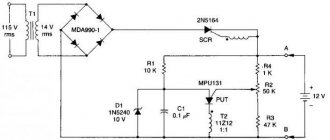
A soft starter with speed control on a thyristor KU 202 is widely used due to its very simple design (diagram 1). Connecting it does not require any special skills. Radio elements for it are very easy to obtain. This regulator model consists of a diode bridge, a variable resistor (acts as a U regulator) and a thyristor tuning circuit (supplying U to the control output with a nominal value of 6.3 volts) from a domestic manufacturer.
Scheme 1. Electrical diagram of the indoor unit with speed control and soft start (electrical circuit diagram)
Due to the size and number of parts, this type of regulator can be built into the body of a power tool. In addition, the variable resistor knob should be removed and the speed controller itself can be modified by integrating a button in front of the diode bridge.
The basic principle of operation is to regulate the speed of the electric motor of the tool by limiting the power in manual mode. This circuit allows you to use power tools with a power of up to 1.5 kW. To increase this indicator, it is necessary to replace the thyristor with a more powerful one (information about this can be found on the Internet or in a reference book). In addition, you need to take into account the fact that the thyristor control circuit will differ from the original one. KU 202 is an excellent thyristor, but its significant drawback is its configuration (selection of parts for the control circuit). To implement a soft start in automatic mode, scheme 2 is used (soft starter on a microcircuit).
Minus control
The above translated diagrams are perfect for use in a car. However, the complexity of some electrical circuits lies in the fact that some of the contacts are connected to the positive, and some to the negative (common wire or body). To control the above circuit by minus power, it needs to be slightly modified. The transistor needs to be replaced with a p-channel one, for example IRF9540N. Connect the negative terminal of the capacitor to the common point of three resistors, and connect the positive terminal to the source of VT1. The modified circuit will have power with reverse polarity, and the control positive contact will be replaced by a negative one.
make up an engine from a car generator
- Megatheronosaurus
- Group: Donator
- Messages: 17,783
1. the generator is 3-phase, which means that in engine mode it also needs 3 phases 2. You can’t get 3 phases without a controller, and since this is a synchronous motor, the frequency must be controlled explicitly from the throttle 3. increasing to 24.48V will allow you to get more power with less losses
I found everything here, even with sources for repetition - freebie
Yes, you need to understand that you will have to “enter the topic” if you do this and you will need your own firmware and possibly other changes to the scheme
- looking for a button
- Group: Users
- Posts: 16,458
what is the engine for specifically?
When I was young, I tried to invent a motor/wheel and even rode on it a little (the brushes burned out), although I drank a lot with the turner) the basis was a starter-generator from a scooter. but even if they had solved the issue with brushes, it would hardly have been possible to protect the structure from water
- experienced forum member
- Group: Disabled
- Posts: 1,405
Nagisa (15.03.2017 - 07:34) :
Nagisa (15.03.2017 - 07:34) :
Garfield (03/15/2017 - 09:02):
It depends on the power - if the exhaust is 200.300 watts, then it will be on the lisaped. And if it’s half a kilowatt or more, then you can even build a 4-wheel drive, even if it’s for a child at the dacha) Starters and engines don’t work as well as Shurik. The resource is short, the bearings are feg, and the starter has low efficiency, the gaps are large, and the A5 is not designed for long-term operation. It's a pity - I have them. Moreover, there is finally one very small one, from a boomer, maybe I’ll take a closer look at it) The genes are the most vitamin-efficient ok + the bearings are tolerable. 2Khz-cho there in Ketai engines, but the gene on the knee can be repaired at any time, like new. I ordered a kit from Ali, of course, but I saw this topic with Gena on the internet - I’m eager to try it, chokak) by the way, I have a disassembled Inkarovskaya electric wheelchair for the disabled. And somewhere there’s even electronics lying around with it. But there seems to be a maximum of 7 km/h + people complain that the plastic wheels are caused by overheating. At first I also wanted to experiment with it, but after I learned about this feature, I put it aside. Although I started watching videos now, there are controllers that have 3 wires going to the motor. I found a couple of relative diagrams. Maybe if you disassemble the gene and draw the ends of the windings outward, then it might work? Well, with a purchased controller and throttle control? What do you say (but preferably not very rudely), guru?) PS: I’ll look on bourgeois sites, there seems to be more detail there. Here are a couple of links as an example. They drive quite briskly. I'll probably get the controller ready soon and order the controller)
Post edited by rtyuehe: 03/16/2017 - 08:00
Source: teron.online
Regulator for soldering iron on a microcircuit
The option is not simple, but it has its advantages. Smooth voltage regulation at the load from 0 to 2 kW and no interference. When operating at high power, it is necessary to install a radiator on VS1.
Homemade soldering iron regulator without interference
K561LA7 - K176LA7. KD503A - KD514A, KD522A. KT361V - KT326V, KT361A.
A simple circuit for a 36 volt soldering iron
This scheme is quite working with a minimum of details.
A simple circuit for a low-voltage AC soldering iron regulator
There are similar schemes for regulating the mains voltage. There is only a smaller adjustment limit here.
Making a motor from a car generator
An interesting way to use a generator in engine mode:
1) connect the corresponding arms of the controller output stage to the winding terminals
2) we supply a normalized current to the excitation winding
The diode assembly could not be removed; it would still need to be installed.
It works because generator - a synchronous electrical machine, reversible, i.e. The drive can be used by both a generator and an engine.
PS: I ordered a BLDC controller board for my tentacles (without everything)
No duplicates found
Did you use a star or a triangle? I would like to see the numbers. Power and efficiency that were obtained in engine mode.
Not long ago, one of the world's major automakers finally introduced a combined starter/generator into the car. It’s not clear why not 10-15 years ago?
Burenkov K. E. Integrated starter-generator - the basis of promising car designs / K. E. Burenkov, Yu. A. Kupeev, A. N. Agafonov // Automotive electrical equipment. 2001. No. 3–4. P. 23.
You can read the file itself, it’s fresh, here:
Motor generators and starter generators are often used in
hybrids. Or in a car with a Start-Stop system.
Also an interesting file:
I thought for a long time about making such a joke towards the author who “invented” it, but there was a lot of swearing and something about 8-9 grade physics. In general, an electric motor as an electric motor has greater efficiency. And for that matter, it is better to use a starter.
Efficiency is determined by the physical characteristics of the electric machine and the characteristics do not change when changing the operating mode, as does the efficiency.
Then copy it completely)
The priority function of an electric machine determines its design features, as a result of which the reversibility becomes uneven. Thus, the electric generator will have a slightly higher efficiency than a correspondingly sized electric motor used as a generator.
This is not a copy, this is common sense.
Thus, the electric generator will have a slightly higher efficiency than a correspondingly sized electric motor used as a generator.
Your copy-paste implies various emails. machines, not the same one. What they have in common is: how does an electric motor of appropriate size used as a generator
In general, an electric motor as an electric motor has greater efficiency.
Thus, the electric generator will have a slightly higher efficiency than a correspondingly sized electric motor used as a generator.
The video clearly uses an electric generator as a motor, which, according to copy-paste from the wiki, supposedly makes it a little more efficient than an electric motor used as a generator (in fact, no, because the same electric motor is used for generation and movement . car).
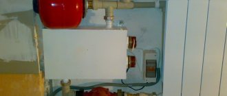
Installing a softstarter
I tried it on for starters:
Trial installation of the soft starter unit
The height is the same, the width is the same, only the length is a little longer, but there is room.
Now a question about control circuits. The contactors in the original circuit were switched on with a voltage of 24 VAC, and our ABBs are controlled by a voltage of at least 100 VAC. There is a need for an intermediate relay or a change in the supply voltage of the control circuit.
However, on the official ABB website I found a diagram that shows that this device can also operate at 24 VAC. I tried my luck - it didn’t work, it won’t start...
Well, we install an intermediate relay that brings the voltage to the desired level:
Example of installation of a soft start system for electric motors
Here's from another angle:
Example of installation of a soft start system for electric motors
That's all. The intermediate relays were called 07KM11 and 07KM21. By the way, they are also needed for additional circuits. Through them, indicators and dry contacts for an external device are turned on (not yet used, in the old circuit - orange wires).
When I wanted to use the control directly, without a relay (24 VAC), I planned to run the power indicators through the Com – Run contacts, which are now left unused.