A battery charge controller is a circuit board that protects the battery from power surges, overcharging, or “deep discharging.” Let's talk about the features of such devices, their types and connection methods.
The controller protects the battery from voltage surges.
What is a battery charge controller
The charge controller works on different principles, depending on the type of battery to which it is connected. Mobile phones, smartphones, tablets, and laptops use a BMS board (chip) with electronic elements soldered onto a lithium-ion battery. If you exclude the protection board from the circuit, the battery will quickly fail or explode due to violations of operating rules.
Wind generators use electronic components. External controllers are connected to solar panels. The latter are selected based on the type of batteries for storing electrical energy. The latter are often presented in lead-acid version.
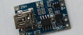
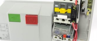
Battery charge controller dimensions.
Three-level regulation system
The quality of regulation of such structures is much higher than that of those previously discussed. Previously, mechanical designs were used, but today non-contact devices are more common. All elements used in this system are the same as those discussed above. But the operating principle is slightly different. First, voltage is applied through a divider to a special circuit in which information is processed. It is possible to install such a generator voltage regulator relay (Ford Sierra can also be equipped with similar equipment) on any car if you know the device and connection diagram.
Here the actual value is compared with the minimum and maximum. If the voltage deviates from the value that is set, then a certain signal appears. It is called a mismatch signal. It is used to regulate the current flowing to the excitation winding. The difference from a two-level system is that there are several additional resistances.
Functions
Controllers are designed for:
- Observations of the charging process. When the capacity is restored from 0 to 10%, the preliminary accumulation of capacity works. From 10 to 70-80% there is an increase in the filling rate with direct current. Recharging is slower due to increased resistance in the circuit.
- Drawdown adjustments. Protects the electrical circuit from short circuits and voltage sags.
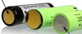
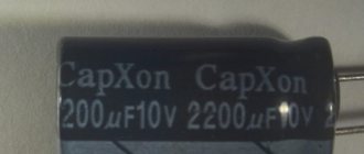
- Recharge locks. Each battery has a maximum voltage limit (for Li-Ion it is about 4.2 V). Having reached the specified number, the power is automatically turned off, preventing the battery from swelling and exploding.
- Deep discharge protection. If the battery voltage drops below a critical value (3 V in Li-Ion), the nominal capacity is lost and the battery life is reduced.
- Balancing. Monitors uniform charging of all parts of the electrical circuit, increasing the service life of the battery.
- Temperature observations. When overheating or hypothermia occurs, the thermistor is triggered, which turns off the power supplied to the battery.
All parameters are set to the microcircuit or controller at the production stage.
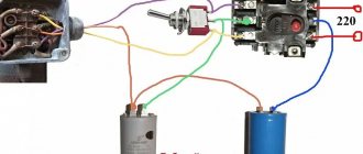
Generator operation
When the rotor begins to rotate, some voltage appears at the generator output. And it is supplied to the excitation winding through a control element. It is also worth noting that the generator set output is connected directly to the battery. Therefore, voltage is constantly present on the excitation winding. When the rotor speed increases, the voltage at the generator set output begins to change. A voltage regulator relay from a Valeo generator or any other manufacturer is connected to the generator output.
In this case, the sensor detects the change, sends a signal to a comparing device, which analyzes it, comparing it with a given parameter. Next, the signal goes to the control device, from which it is supplied to the actuator. The regulatory body is able to reduce the value of the current that flows to the rotor winding. As a result, the voltage at the generator set output is reduced. In a similar way, the mentioned parameter is increased in the event of a decrease in rotor speed.
Types of controllers
The principle of charging the battery depends on the installed equipment. The controllers listed below are used for solar panels; similar devices are used in other areas of renewable electricity.
Some make homemade devices that are inferior to purchased models in a number of characteristics.
Devices On/Off
An entry-level device that cuts off power once the battery reaches its maximum voltage. This protects the battery from overheating and overcharging.
“Protection” is triggered when 70-85% of the capacity is restored—the voltage peak. Next, the current should decrease and charge the battery to 100% in 1-3 hours, but this does not happen due to the features of the device. As a result, constant undercharging reduces the service life and capacity of the battery.
PWM
The controller is called PWM and operates on the principle of pulse-width modulation of current. Similar to the printed circuit board in smartphones with lithium-ion power supplies, the device reduces the incoming voltage when it reaches its peak and brings charging to 100%. The device costs more than the previous version, but allows you to save “energy reservoirs”.
PWM Battery charge controller.
MPPT
The device contains algorithms for measuring the current and voltage of the power supply system and determining the optimal ratio of parameters for stable operation of the connected station. According to statistics, MPPTs distribute energy received from an external power source 35% more efficiently than PWM options. Considering the cost of the device, it is usually used to automate “solar farms”. Due to the reduced cost, it is more practical to use PWM in private homes.
Hybrid devices
Such controllers combine the features of PWM and MPPT. They are used to distribute energy obtained from wind generators, which are combined with solar panels. The main difference from conventional models is the current-voltage parameters.
Hybrids “even out” the received energy and distribute it evenly between the batteries. This need arises for wind turbines, which generate electricity intermittently.
Hybrid device.
Three circuits of simple current regulators
There are a lot of voltage regulator circuits on the network for a variety of purposes, but with current regulators things are different. And I want to fill this gap a little, and present to you three simple DC regulator circuits that are worth adopting, as they are universal and can be used in many homemade designs.
In theory, current regulators are not much different from voltage regulators. Please do not confuse current regulators with current stabilizers; unlike the former, they maintain a stable output current regardless of the input voltage and output load.
A current stabilizer is an integral part of any normal laboratory power supply or charger; it is designed to limit the current supplied to the load. In this article we will look at a couple of stabilizers and one regulator for general use.
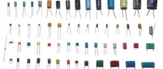
In all three options, shunts, essentially low-resistance resistors, are used as a current sensor. To increase the output current of any of the listed circuits, it will be necessary to reduce the shunt resistance. The required current value is set manually, usually by rotating a variable resistor. All three circuits operate in linear mode, which means the power transistor will become very hot under heavy loads.
The first scheme is characterized by maximum simplicity and accessibility of components. There are only two transistors, one of them is the control one, the second is the power transistor, through which the main current flows.
The current sensor is a low-resistance wirewound resistor. When connecting an output load, a certain voltage drop is formed across this resistor; the more powerful the load, the greater the drop. This voltage drop is enough to trigger the control transistor; the greater the drop, the more the transistor is open. Resistor R1 sets the bias voltage for the power transistor, it is thanks to it that the main transistor is in the open state. Current limitation occurs due to the fact that the voltage at the base of the power transistor, which was formed by resistor R1, roughly speaking, is damped or shorted to the power ground through the open junction of the low-power transistor, this will close the power transistor, therefore, the current flowing through it decreases down to complete zero .
Resistor R1 is essentially an ordinary voltage divider, with which we can set the degree of opening of the control transistor, and therefore control the power transistor by limiting the current flowing through it.
The second circuit is based on an operational amplifier. It has been used several times in chargers for car batteries. Unlike the first option, this circuit is a current stabilizer.
As in the first circuit, there is also a current sensor (shunt), the operational amplifier records the voltage drop across this shunt, all according to the circuit already familiar to us. The operational amplifier compares the voltage on the shunt with the reference voltage, which is set by the zener diode. With a variable resistor we artificially change the reference voltage. The operational amplifier, in turn, will try to balance the voltage at the inputs by changing the output voltage.
The output of the op-amp drives a high-power field-effect transistor. That is, the principle of operation is not much different from the first circuit, except that there is a reference voltage source made on a zener diode.
This circuit also operates in linear mode and the power transistor will become very hot under heavy loads.
The latest circuit is based on the popular LM317 stabilizer integrated circuit. This is a linear voltage stabilizer, but it is possible to use the microcircuit as a current stabilizer.
The required current is set by a variable resistor. The disadvantage of the circuit is that the main current flows precisely through the previously indicated resistor and naturally it needs a powerful one; the use of wirewound resistors is highly desirable.
The maximum permissible current for the LM317 microcircuit is 1.5 amperes; it can be increased with an additional power transistor. In this case, the microcircuit will already act as a control chip, so it will not heat up, instead the transistor will heat up and there is no escape from it.
Every car owner needs a battery charger, but it costs a lot, and regular preventive trips to a car service center are not an option. Battery service at a service station takes time and money. In addition, with a discharged battery, you still need to drive to the service station. Anyone who knows how to use a soldering iron can assemble a working charger for a car battery with their own hands.
Connection methods
The connection depends on the type of device.
PWM
Especially for users, next to the terminals there are indications of what to connect to them. It is necessary to take into account the strict sequence: 1. Connect the battery. 2. Turn on the fuse on the board, next to the “+”. 3. Insert the solar panels contacts. 4. Connect a 12 or 24 V test lamp.
It is important to make connections in strict sequence, taking into account the markings on the terminals and the polarity of the wires.
MPPT
The connection is noticeably different from PWM:
- The solar panel is connected to the inverter.
- From it, the plus is brought into the device. A fuse is installed on the negative cable.
- The battery is connected to the second plus and minus using fuses.
- The inverter and controller are connected to ground.
The sequence and type of connection will differ slightly:
- Move the terminals to the inactive position.
- Remove the fuses.
- Connect the batteries.
- Connect solar panels.
- Take care of grounding.
- Add a temperature sensor to the circuit.
- Replace fuses, activate terminals.
FakeHeader
Comments 102
Is there a file for the printed circuit board?
How many volts are lost at the output?
I did everything according to your scheme. The current is regulated only between 4-5A! tell me what the problem is!
But no one said a word about the choice of transistor and possibly radiator :). It’s even easier to make a current limiter on lm317, then essentially one TO-220 body and a couple of resistors