Communication entry points are those places through which various engineering communications enter your building or private house from the outside. Communications inputs come in different diameters and for different engineering purposes:
- Sewerage
- Water supply
- Electricity
- Gas supply
- Heating
- Ventilation and air conditioning
If the openings through which communications enter buildings are located underground (in the basement or basement) or on the roof, balcony or open terrace, then this may be a potential threat of leaks. Places where pipes, cables, etc. They enter your building from the street - these are weak points through which water and moisture can subsequently penetrate into the room. This is why special attention should be paid to their correct installation and waterproofing.
Injection of communication inputs – Injection waterproofing
As mentioned earlier, injection of bushings is one of the most effective ways to protect this area from water, since injection compounds are supplied under pressure and have the ability to fill absolutely all voids and spaces. The injection essentially gets into the space between the concrete and the sleeve, casing, cable, pipe and fills it and possible voids and microcracks around it. Thus, injection compounds or materials block water and prevent it from penetrating into the room. Injection waterproofing is mainly used when builders did not pay due attention to the issue of sealing the entrance points of utility networks during construction, which ultimately led to the formation of leaks in the building.
You can read more about the injection method of waterproofing in the article – “Injection waterproofing”
Installation of a sealed inlet block for asbestos-cement pipes
2.1. The installation of a sealed inlet block for asbestos-cement pipes is carried out in the following sequence:
1) asbestos-cement pipes are selected for the installation of the inlet block. In this case, the internal diameter of the pipes must be 100 mm, and the channels must have the correct circular shape (deviation from the specified conditions may create difficulties in installing a sealing device in the channel).
The selection of asbestos-cement pipes is carried out using the fittings of a sealing device for a free channel (AGUSK), the disk of which, welded to the stud, is inserted into the hole of the end of the pipe by 100 mm. In this case, the disk should fit freely into the hole;
2) a concrete mixture of grade 200 is produced, consisting of gypsum-alumina expanding cement grade 300 (GOST 11052-74), sand and fine-grained gravel.
3) notches are applied to the inner surfaces of the opening using a chisel and sledgehammer, after which the surfaces are generously moistened with water;
4) the bottom row of pipes is laid on a layer of concrete mixture 50 mm thick. The distance between the pipes should be 25 mm;
5) a layer of concrete mixture 50 mm thick is laid on a row of pipes, which is used to fill all the gaps between the pipes using a shovel and a trowel with compaction;
6) the remaining rows of pipes are concreted similarly, so that a vertical distance of 25 mm is maintained between the rows of pipes;
7) when concreting a pipe block, it is recommended to use an IV-19A type site vibrator to compact the concrete mixture. Compaction should be done layer by layer in two or three passes until laitance appears on the surface of the concrete layer.
The upper two rows of pipes are sealed manually by bayoneting with a shovel;
 In the process of concreting a block of pipes, the entire space between the pipes, rows of pipes, as well as between the pipes and the surfaces of the foundation opening must be filled and compacted with a concrete mixture.
replacement of MDF panel on the entrance door in Yekaterinburg
Sealing of bushings prices and costs
Below are the average prices for work on sealing the entry points of various communications. Prices and cost of work vary depending on the diameter and list of work performed. The prices below do not take into account the cost of sealants or other materials used.
| Name of works | Inlet diameter | Unit | Price in rubles |
| Waterproofing of service entry points: – Installation of a technological fine – Surface preparation – Layer-by-layer compaction of expanding sealant | 50 | 1 PC | 24000 |
| 110 | 1 PC | 25000 | |
| 160 | 1 PC | 26000 | |
| Waterproofing of utility lines: – Installation of a process duct – Surface preparation – Installation of a bentonite profile – Layer-by-layer compaction of expanding sealant | 50 | 1 PC | 34000 |
| 110 | 1 PC | 37000 | |
| 160 | 1 PC | 39000 | |
| Waterproofing of communication inputs with the Stopaq system, including tying with an elastic profile and its sealing | 180 | 1 PC | 39000 |
| Sealing of communication inputs using the Injection method: – Joining the abutment seam / installing fines – Layer-by-layer compaction of repair composition – Marking injection centers, drilling holes (holes) – Installing packers (into holes) – Injection work using special equipment – Removing packers – Sealing injection centers with special composition | 50 | 1 PC | 69000 |
| 110 | 1 PC | 74000 | |
| 160 | 1 PC | 79000 |
Sealing of inputs price in estimate
The above prices do not take into account the complexity of the work and other factors that may affect the prices and the final cost of the work. If you want an accurate estimate with the final price per unit and the final cost taking into account the materials and work used, then you need to call a specialist or engineer from a company that specializes in waterproofing to inspect your facility. An experienced engineer, having familiarized himself with your facility and the specific situation with inlets and leaks, will be able to draw up a professional technical specification, which he will submit to the estimate department, which in turn will provide you with a detailed estimate, where you will see not only the final cost of the estimate, but also the prices for every position.
Sealing passages when laying cables along walls and ceilings
LOCAL RESOURCE STATEMENT GESNm 08-02-155-02
| Name | Unit |
| Sealing passages when laying cables along walls and ceilings | 100 m of laid cable |
| Scope of work | |
| 01. Sealing. | |
The price contains only direct costs of work for the period 2000
(prices in Moscow and the Moscow region), which are calculated according to
2009
. To draw up an estimate, you need to apply the conversion index to the prices of the current year to the cost of the work.
You can go to the pricing page, which is calculated based on the standards of the 2014 edition with additions 1 The basis for use in calculating labor costs and material consumption is GESN-2001
| № | Name | Unit Change | Labor costs |
| 1 | Labor costs of assembly workers Level 4 | person-hour | 1,26 |
| Total labor costs for workers | person-hour | 1,26 | |
| Workers' compensation = 1.26 x 9.62 | Rub. | 12,12 | |
Work schedule. Automatic construction according to estimates.
height of bathroom door with threshold
| № | Cipher | Name | Unit Change | Consumption | Article number Rub. | Total RUB. |
| 1 | 509-0988 | General purpose asbestos cord SHAON brand with a diameter of 3-5 mm | T | 0,00003 | 26950 | 0,81 |
| Total | Rub. | 0,81 | ||||
TOTAL PRICE: 12.93 RUR.
Look at the cost of this standard as amended in 2022 open page
Compare the price value with the value of FERm 08-02-155-02
To draw up an estimate, the price requires indexation of the transition to current prices. The price is based on the GESN-2001 standards, as amended in 2009.
in
2000
.
To determine intermediate and final price values, the DefSmeta
Source
Waterproofing and sealing of cable entries
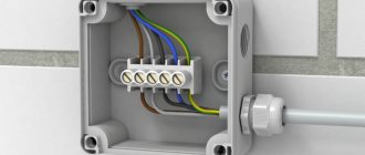
It is best to install cables into the house through a sleeve specially installed for this purpose, as this will provide the opportunity to add new cables and repair old ones. Cable entries entering the building must be sealed using non-flammable waterproofing material. In addition to various sealants, there are also many devices on the market for sealing cable glands.
In the regulatory documents of the PUE Chapter 2.1. Clause 2.1.58 and SNiP 3.05.06-85 describe the requirements for cable passages
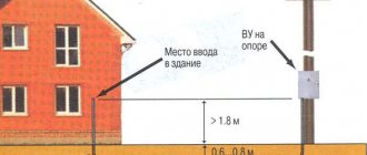
The weakest point of any communications is considered to be the area that runs in the façade of buildings and is subject to connection to a distribution device or one of the types of distribution mechanisms. To prevent the occurrence of emergency situations, cable entries in hazardous areas are sealed.
Requirements and standards
The requirements according to which cable glands are sealed are reflected in the relevant SNiP and PUE. In particular, the documentation reflects the condition that the cable gland must have the ability to prevent further spread of flame, retain water, and extinguish combustion processes. If necessary, the master must be able to quickly replace a section of communications.
Solution
Sealing the cable entry is carried out in several ways. Until recently, heat-resistant polyurethane foam was widely used, which was evenly distributed over the entire surface of the cable located in the pipe. After polymerization of the composition, excess polyurethane foam is cut off and compacted, if necessary. Specially created recesses are filled with cement mortar.
Today, such a solution can confidently be called outdated. The modern market also offers more technologically advanced systems for sealing bushings, which have proven their effectiveness in practice.
Innovative seals imply reliable sealing of the bushing using the heat shrink method. Heat-shrinkable seals successfully cope with the task of sealing cable entries into channels. Special kits for the work consist of a special tube and mastic that acts as a sealing compound. When choosing a tube, specialists are guided by the outer diameter of the cable channel. The final result when using such kits depends on the parameters of the pipe used. If the diameter of the cable inserted into the hole is minimal, mastic tape is additionally wound under the product. Also, the use of a mastic sealant is justified when inserting several cables into one hole. In this case, mastic tape allows you to seal the space between adjacent cables.
If the diameters of the cable and the channel in which it is located differ significantly, then it is necessary to use special heat-shrinkable adapters. Before carrying out installation work, it is possible to give the part the necessary geometric parameters. It is also possible to cut the product into several fragments using a guillotine knife.
In most cases, a piece of sealant 20 cm long is sufficient for installation operations. In exceptional cases, products of increased length are used. This is relevant, for example, in the case of sealing several cables at the same time. If the diameter of the cable channel does not exceed 80 cm, provided that a single cable is used, parts up to 15 cm in length are allowed.
The use of special sealing flanges is an excellent solution. It allows you to avoid storing a large number and wide range of adapters, since the products are considered universal. Our company is the exclusive distributor of sealing flanges in the CIS. All systems have successfully passed the certification procedure. Sealing pipe entry into a building
The presence of communications in a building is an essential condition for its comfortable operation. For this reason, the issue of sealing pipes entering a building is receiving increased attention today. Ignoring the need to perform similar work, builders do everything possible with their own hands to quickly destroy the building. Moisture will penetrate into the building through the technological openings, which will have a destructive effect on the foundation and other structural elements of the building.
What needs to be isolated?
Sealing the entrance of pipes into a building is necessary when laying gas, water, and sewer networks. It is the area where pipelines enter the building that is considered the most vulnerable in the entire waterproofing system. Craftsmen pay special attention to sealing issues in order to maximize the service life of the building and maintain its strength under various weather and climatic conditions.
All planned work is carried out in accordance with current technical requirements. The modern construction market offers various devices and materials to solve this problem. It is extremely important to make the sealing of pipes entering the building durable and of high quality, otherwise it will quickly cease to fulfill its main function.
Peculiarities
Special sealing elements are made from high-quality materials that demonstrate excellent adhesion and increased elasticity. Provided that they make the right choice and adhere to the technology for performing installation work, craftsmen can achieve maximum tightness of all joints of communications and building walls, and increase the service life of utility networks.
The joints of elements made of dissimilar materials deserve special attention. These areas require especially careful waterproofing, since they are the most vulnerable. Quite often, experts recommend additional injection of elastic polyurethane resins, which significantly increase the strength and reliability of the connection.
Insulation of inputs
Waterproofing the inputs of communication networks into a building is the most important event at the construction stage. Most often, inexperienced craftsmen encounter certain difficulties when carrying out work if they use outdated methods of filling voids with bitumen or cement mastics. These materials have a significant drawback, which is the impossibility of taking into account the degree of expansion of substances with heterogeneous structures: cement, plastic and metal. The materials also demonstrate insufficient resistance to significant external fluid pressure.
Innovative solutions
Our company is the exclusive supplier of compact seals in the CIS. These annulus seals have revolutionized the construction market. They allow you to achieve perfect sealing of pipeline entries and increase the durability of the building. Thanks to the use of a unique sealing technology, the joint between the structural elements of communication networks becomes completely impenetrable to gaseous and liquid media. All products are certified. Sealing and insulating flanges
There is an opinion that flange connections are sealed detachable connections that have a simple design. This is a serious misconception. Sealing a flange connection is a rather difficult task to solve, the solution of which requires careful preparation.
Compound
The flange connection has a traditional design that includes two metal flanges and a sealing surface. The sealant is an elastic and elastic material, which acts as a gasket when sealing and insulating the flanges. There are also less popular types of structures, but they are quite rare. These are butel and other types of connections without fasteners.
Classic flange connections operate in self-sealing mode. Less common in such systems are gland seals, where contact stresses are created on the cylindrical surfaces being sealed.
Innovative solutions
As new technologies become available, alternative methods for sealing and insulating flanges are becoming more common. Flange gaskets have an improved design that provides a more effective sealing of elements.
The main function of a flange connection is to ensure safe and reliable operation of technological objects, regardless of their scope of application. When sealing and insulating flanges, specialists strive to maintain the tightness and strength of the structure over a certain period of time. Merely selecting the correct gasket and assembling the unit is not enough. Even a mechanism whose assembly was completed a few minutes ago operates with certain losses in the working environment. To eliminate this undesirable phenomenon, the assembly is additionally subjected to compaction.
Typically, the cause of an emergency or depressurization of a mechanism is the appearance of signs of roughness, mechanical defects and changes in the shape of the sealing elements. Many similar defects are congenital.
Tightness of connection
The flange connection will be leak-tight provided that during its assembly the master strictly followed the operation technology. Equally important is adequate quality control of the connection being created. It is important to select sealing elements that meet high quality requirements. This will guarantee a tight flange connection.
Selecting a sealing element
The reliability and durability of the flange assembly is determined by the type of gasket and the quality of assembly of the structural elements of the mechanism. Our company is the exclusive supplier of flange seals from a world-famous manufacturer. We supply the highest quality products to the CIS countries and guarantee their unsurpassed reliability. All products have successfully passed the certification procedure, which confirms their excellent technical and operational characteristics.
Certificate of sealing of utility lines in a building sample
If you are performing work or are having work performed on sealing various engineering inputs into your structure or building, then you can hand over or accept this work based on the act of sealing the inputs (outputs). On our website you can download several samples of such acts.
- The act of sealing the inputs (outputs) of utility lines in the basement
You can draw up these acts yourself by downloading the necessary sample acts and filling them in with the details of the contractor and the customer.
Sealing passages when laying cables along walls and ceilings
FEDERAL UNIT PRICE FOR FARMS 08-02-155-02
| Name | Unit |
| Sealing passages when laying cables along walls and ceilings | 100 m of laid cable |
| Scope of work | |
| 01. Sealing. | |
The price indicates the direct costs of work for the period 2000
(Federal prices), which are calculated based on
2014 standards with additions 1
. The conversion index to current prices must be applied to this value.
You can go to the page of the same standard, which is calculated according to the GESN 2022 edition
| Total (RUB) | Workers' compensation | Machine operation | Pay for drivers | Cost of materials | Labor costs (person-hours) |
| 10,72 | 9,72 | 1 | 1,01 |
TOTAL PRICE: 10.72 RUR.
Look at the cost of this standard as amended in 2022 open page
Look at the resource part of the price in the GESNm standard 08-02-155-02
When used in an estimate, the price requires indexation to translate into current prices. The price is compiled according to the standards of GESN-2001 as amended in 2014 with additions 1
in
2000
.
Source
What to consider when choosing a sealant for sewer pipelines
Plumbing sealant for sewerage is not difficult to buy. But the variety of offers from manufacturers poses a choice problem for buyers. What product should I buy? And how to guide this will be discussed further.
- Tape plumbing sealant. These building materials are classified as progressive types. The distinctive feature in this case is ease of installation and high efficiency.
- Silicone plumbing sealants. Their base is silicone rubber. The vulcanization process occurs under the influence of moisture in the air.
- Technical sulfur. It is used for cast iron sewer pipes.
- Epoxy resin. Glue based on it is the most common household sealant.
- Portland cement. It is used when caulking socket joints of cast iron sewer pipes.
- Asphalt mastic. Most often used for working with ceramic sewer lines.
- Strand of resin and rope. This is usually used to seal cast iron and ceramic pipes.
Is fire-resistant foam in cable penetrations a crime or a blessing?
Communicating with installers of electrical equipment from various regions of Russia, I was surprised to learn that almost all of them, when laying power or low-current cable lines through fire barriers (walls, partitions, etc.), use fire-resistant polyurethane foam for sealing.
To my questions “WHY?”, they answer that everyone does it, and it’s “FIRE RESISTANT”, and there’s even a certificate, and it’s more convenient to work with it……foamed it and that’s it…. And no one has answered how this is regulated. Let's figure it out. What does the legislation say about this?
Federal Law of July 22, 2008 No. 123-FZ “Technical Regulations on Fire Safety Requirements.” Article 137. Fire safety requirements for building structures. clause 4. The intersections of enclosing building structures with cables, pipelines and other technological equipment must have a fire resistance limit not lower than the required limits established for these structures.
SP 2.13130.2012 “Fire protection systems. Ensuring the fire resistance of protected objects.” clause 5.2.4 The intersections of building structures with regulated fire resistance limits of cables, pipelines, air ducts and other technological equipment must have a fire resistance limit not lower than the limits established for the structures being crossed. The fire resistance limits of intersections (penetrations) are determined according to GOST 30247, GOST R 53299, GOST R 53306, GOST R 53310.
SP 76.13330.2016 “Electrical devices. Updated version of SNiP 3.05.06-85" clause 5.25 After performing electrical installation work, the general contractor is obliged to seal holes, grooves, niches and sockets, ensuring the rated fire resistance limit of the intersected enclosing structure.
PUE 7. “Rules for electrical installations.” Edition 7. Section 2. Electricity sewerage. Chapter 2.1. Electrical wiring clause 2.1.58. In places where wires and cables pass through walls, interfloor ceilings or where they exit outside, it is necessary to ensure the possibility of changing electrical wiring. To do this, the passage must be made in a pipe, duct, opening, etc. In order to prevent the penetration and accumulation of water and the spread of fire in places of passage through walls, ceilings or exits to the outside, the gaps between wires, cables and the pipe (duct, opening) should be sealed etc.), as well as backup pipes (ducts, openings, etc.) with an easily removable mass from non-combustible material. The seal must allow replacement, additional installation of new wires and cables and ensure the fire resistance limit of the opening is not less than the fire resistance limit of the wall (floor).
GOST R 53310-2009 “Cable penetrations, sealed entries and busbar penetrations. Fire safety requirements. Test methods for fire resistance." 4.1 Cable penetrations, sealed entries and busbar penetrations made in enclosing structures with standardized fire resistance limits or fire barriers must have a fire resistance limit not lower than the fire resistance limit of the structure being crossed. 4.2 The design of the penetrations must provide the possibility of replacing and (or) additional laying of wires and cables, and the possibility of their maintenance.
And so on….. It is not stated anywhere exactly what materials should be used. Accordingly, fire-resistant polyurethane foam “seems to be suitable” in terms of parameters. This is where the main mistake is immediately revealed. SP 2.13130.2012 states that the fire resistance limits of intersections (penetrations) are determined according to GOST 30247, GOST R 53299, GOST R 53306, GOST R 53310. Cable penetrations include GOST R 53310. What is a cable penetration? cable penetration : a structural element, product or prefabricated structure intended for sealing the passage of cables through enclosing structures with standardized fire resistance limits or fire barriers and preventing the spread of fire into adjacent rooms for a specified time. Cable penetration includes cables, embedded parts (ducts, trays, pipes, etc.), sealing materials and prefabricated or structural elements.
Acrylic and silicone based sealants
Silicone sewer pipe sealant has become the most popular installation option. These products comprise additives and active ingredients.
The main component of the substance is a material made of silicone or acrylic rubber. Ultimately, it allows for a strong fixation of the pipe connection.
Based on the type of hardener, silicone pipe sealant is divided into the following types:
- Acid. This product is distinguished by its low cost; it is not recommended to lay it on surfaces that react poorly to acid. A characteristic feature of this version of plumbing sealant is that it reacts with almost all metals. The only exception is stainless steel.
- Neutral. This is a more versatile material. It is suitable for most types of installation, which leads to a higher cost.
Using silicone sealants, you can seal sewer pipe materials made of metal and plastic. Working with them is not difficult.
They are easily squeezed out using a mounting gun. When you don’t have one, you can take a regular hammer. It needs to be inserted into the tube and pressed like a piston.
Annex 1
Sealing devices for occupied channels
| Size number | Standard size | Cable capacity with core diameter, mm | ||||||
| Cable brand | ||||||||
| TPP | tpsp | |||||||
| 0,32 | 0,4 | 0,5 | 0,7 | 0,4 | 0,5 | 0,7 | ||
| I | GUZK-4-16 | 50×2 | 25×4 | — | — | — | — | — |
| II | GUZK-4-24 | 100×2 | 50×4 | 50×2 | — | — | — | — |
| 150×2 | 50×2 | 25×4 | — | — | — | — | ||
| III | GUZK-4-29 | 200×2 | 100×2 | 50×4 | 25×4 | 100×2 | — | — |
| 75×4 | ||||||||
| IV | GUZK-4-35 | 300×2 | 200×2 | 100×2 | 50×2 | — | 100×2 | — |
| 150×2 | 75×4 | |||||||
| 100×4 | ||||||||
| V | GUZK-3-37 | — | 150×4 | 150×2 | 50×4 | 200×2 | — | — |
| 100×4 | ||||||||
| VI | GUZK-2-41 | 400×2 | 200×4 | 200×2 | 100×2 | — | — | — |
| VIa | GUZKr-2-41 | 300×2 | ||||||
| VII | GUZK-2-45 | 500×2 | — | 150×4 | 75×4 | 300×2 | 200×2 | 100×2 |
| VIIa | GUZKr-2-5 | |||||||
| VIII | GUZK-1-47 | 600×2 | 250×4 | — | — | 400×2 | — | — |
| VIIIа | GUZKr-1-47 | 400×2 | ||||||
| IX | GUZK-1-50 | 700×2 | 300×4 | 200×4 | 150×2 | — | — | — |
| IXa | GUZKr-1-50 | 300×2 | 100×4 | |||||
| X | GUZK-1-54 | 800×2 | 500×2 | — | 200×2 | 500×2 | — | — |
| Xha | GUZKr-1-54 | 350×4 | 600×2 | |||||
| XI | GUZK-1-56 | 900×2 | 600×2 | 400×2 | — | — | 400×2 | 200×2 |
| XIa | GUZKr-1-56 | 400×2 | 250×4 | |||||
| XII | GUZK-1-61 | 1000×2 | 700×2 | 300×4 | 150×4 | 700×2 | 500×2 | — |
| XIIa | GUZKr-1-61 | 450×4 | 500×2 | 800×2 | ||||
| 500×4 | ||||||||
| XIII | GUZK-1-64 | 1200×2 | 800×2 | 350×4 | 300×2 | 900×2 | 600×2 | — |
| XIIIa | GUZKr-1-64 | |||||||
| XIV | GUZK-1-67 | — | 900×2 | 400×4 | 200×4 | 1000×2 | — | 300×2 |
| XIVa | GUZKr-1-67 | 600×4 | 600×2 | |||||
| XV | GUZK-1-72 | — | 1000×2 | 450×4 | 400×2 | 1200×2 | 700×2 | 400×2 |
| XVа | GUZKr-1-72 | 1200×2 | 700×2 | 250×4 | 600×2 | |||
| 500×4 | ||||||||
| 600×2 | ||||||||
Continuation of Appendix 1
| Size number | Standard size | Cable capacity with core diameter, mm | ||||||
| Cable brand | ||||||||
| tg | MCG | MKSSSShp | MKSAShp | ICSG MKSGShp | ||||
| 0,4 | 0,5 | 0,7 | 1,2 | 1,2 | 1,2 | 1,2 | ||
| I | GUZK-4-16 | 50×2 | — | — | — | — | — | — |
| II | GUZK-4-24 | 100×2 | 100×2 | — | 3×4 | — | 1×4 | 4×4 |
| 150×2 | 50×2 | — | 4×4 | — | 1×4 | |||
| III | GUZK-4-29 | 200×2 | 150×2 | 50×2 | 7×4 | — | 4×4 | 7×4 |
| 4×4 | ||||||||
| IV | GUZK-4-35 | 300×2 | 200×2 | 100×2 | 13×2 | 4×4 | 7×4 | 7×4 |
| V | GUZK-3-37 | — | — | — | — | 7×4 | — | — |
| VI | GUZK-2-41 | 400×2 | 300×2 | 150×2 | 21×2 | — | — | — |
| VIa | GUZKr-2-41 | — | ||||||
| VII | GUZK-2-45 | 500×2 | 400×2 | — | — | — | — | — |
| VIIa | GUZKr-2-5 | |||||||
| VIII | GUZK-1-47 | — | — | 200×2 | 32×2 | — | — | — |
| VIIIа | GUZKr-1-47 | |||||||
| IX | GUZK-1-50 | 600×2 | 500×2 | — | — | — | — | — |
| IXa | GUZKr-1-50 | |||||||
| X | GUZK-1-54 | 700×2 | 600×2 | — | — | — | — | — |
| Xha | GUZKr-1-54 | |||||||
| XI | GUZK-1-56 | 800×2 | — | 300×2 | — | — | — | — |
| XIa | GUZKr-1-56 | |||||||
| XII | GUZK-1-61 | 900×2 | 700×2 | — | — | — | — | — |
| XIIa | GUZKr-1-61 | 800×2 | ||||||
| XIII | GUZK-1-64 | — | — | 400×2 | — | — | — | — |
| XIIIa | GUZKr-1-64 | |||||||
| XIV | GUZK-1-67 | 1000×2 | 900×2 | — | — | — | — | — |
| XIVa | GUZKr-1-67 | |||||||
| XV | GUZK-1-72 | 1200×2 | 1000×2 | 500×2 | — | — | — | — |
| XVа | GUZKr-1-72 | 1200×2 | ||||||
Continuation of Appendix 1
| Size number | Standard size | Cable capacity with core diameter, mm | ||||
| Cable brand | ||||||
| tzg | TZAShp | |||||
| 0,8 | 0,9 | 1,2 | 0,9 | 1,2 | ||
| I | GUZK-4-16 | 3×4 | 3×4 | 3×4 | — | — |
| 4×4 | 4×4 | 4×4 | ||||
| 7×4 | ||||||
| II | GUZK-4-24 | 12×4 | 7×4 | 7×4 | 4×4 | — |
| 14×4 | 12×4 | |||||
| 19×4 | 14×4 | |||||
| III | GUZK-4-29 | 24×4 | 19×4 | 14×4 | 7×4 | 4×4 |
| 27×4 | 7×4 | |||||
| IV | GUZK-4-35 | 30×4 | 24×4 | 19×4 | 12×4 | — |
| 37×4 | 27×4 | 19×4 | ||||
| 30×4 | ||||||
| V | GUZK-3-37 | 44×4 | 37×4 | 24×4 | — | 14×4 |
| 48×4 | 27×4 | |||||
| VI | GUZK-2-41 | 52×4 | 44×4 | 30×4 | — | 19×4 |
| VIa | GUZKr-2-41 | 61×4 | ||||
| VII | GUZK-2-45 | — | 48×4 | 37×4 | — | — |
| VIIa | GUZKr-2-45 | 52×4 | ||||
| VIII | GUZK-1-47 | 75×4 | 61×4 | 44×4 | — | — |
| VIIIа | GUZKr-1-47 | 80×4 | — | |||
| IX | GUZK-1-50 | 90×4 | — | 48×4 | — | — |
| IXa | GUZKr-1-50 | 52×4 | ||||
| X | GUZK-1-54 | 102×4 | 75×4 | 61×4 | — | — |
| Xha | GUZKr-1-54 | 108×4 | 80×4 | |||
| XI | GUZK-1-56 | 114×4 | 90×4 | — | — | — |
| XIa | GUZKr-1-56 | |||||
| XII | GUZK-1-61 | — | 102×4 | — | — | — |
| XIIa | GUZKr-1-61 | 108×4 | ||||
| XIII | GUZK-1-64 | — | 114×4 | — | — | — |
| XIIIa | GUZKr-1-64 | |||||
Continuation of Appendix 1
| Size number | Standard size | Cable capacity with core diameter, mm | |||||
| Cable brand | |||||||
| ZKV ZKP | EKPAShp | KSPP | MKT-4 VKPAN | KMG | |||
| 1,2 | 1,2 | 0,9 | 1,9 | ||||
| I | GUZK-4-16 | — | — | 1×4 | 1×4 | — | — |
| II | GUZK-4-24 | 1×4 | 1×4 | 4×4 | — | MKTS VKLAP | — |
| III | GUZK-4-29 | — | — | — | — | ICTP MKTASHp | — |
| V | GUZK-3-37 | — | — | — | — | — | KMG-4 |
| IX | GUZK-1-50 | — | — | — | — | — | KMG-8/6 |
| IXa | GUZKr-1-50 | ||||||
PUE 7. Rules for electrical installations. Edition 7
Section 2. Electricity sewerage
Chapter 2.3. Cable lines with voltage up to 220 kV
Connections and terminations of cables
2.3.65.
When connecting and terminating power cables, coupling designs that comply with their operating and environmental conditions should be used. Connections and terminations on cable lines must be made in such a way that the cables are protected from the penetration of moisture and other harmful substances from the environment into them and that the connections and terminations can withstand the test voltages for the cable line and comply with GOST requirements. ¶ 2.3.66. For cable lines up to 35 kV, end and connecting couplings must be used in accordance with the current technical documentation for couplings, approved in accordance with the established procedure. 
2.3.67. For connecting and locking couplings of low-pressure oil-filled cable lines, only brass or copper couplings should be used. 
The length of sections and installation locations of locking couplings on low-pressure oil-filled cable lines are determined taking into account the replenishment of the lines with oil in normal and transient thermal conditions. 
Stop and half-stop couplings on oil-filled cable lines must be placed in cable wells; When laying cables in the ground, it is recommended to place connecting couplings in chambers that are subject to subsequent backfilling with sifted earth or sand. 
In areas with electrified transport (metropolitan, trams, railways) or with soils that are aggressive to the metal shells and couplings of cable lines, the couplings must be accessible for inspection. 
2.3.68. On cable lines made with cables with normally impregnated paper insulation and cables impregnated with a non-drip compound, cable connections must be made using stop-transition couplings if the laying level of cables with normally impregnated insulation is higher than the laying level of cables impregnated with a non-drip compound (see also 2.3 .51). 
2.3.69. On cable lines above 1 kV, made with flexible cables with rubber insulation in a rubber hose, cable connections must be made by hot vulcanization and coated with anti-damp varnish. 
2.3.70. The number of couplings per 1 km of newly constructed cable lines should be no more than: 
- for three-core cables 1-10 kV with a cross-section up to 3x95 mm 2 4 pcs.;
- for three-core cables 1-10 kV with sections 3x120 - 3x240 mm 2 5 pcs.;
- for three-phase cables 20-35 kV 6 pcs.; for single-core cables 2 pcs;
- for cable lines 110-220 kV, the number of connecting couplings is determined by the design.
The use of undersized cable sections for the construction of long cable lines is not permitted.
TIGHTNESS TESTING OF NEWLY CONSTRUCTED CABLE ENTRY
4.1. All newly constructed cable entries must be tested for leaks.
4.2. Testing the tightness of the input is carried out by blowing it from the outside with a stream of air. Air is supplied from a mobile compressor (for example, type ZIF-55) with a capacity of 5 m3/min using a rubber pressure hose (GOST 10362-76) with an internal diameter of 20 mm. The pressure of the air stream at the outlet of the hose should be 39.2·104 Pa (4 kgf/cm2).
The end of the hose is located at a distance of 100 - 150 mm from the element being tested: the concreted part of the entrance opening or the inlets of asbestos-cement pipes, at the opposite ends of which sealing devices are installed. Each element being tested is blown with air for 1 minute.
4.3. To detect leaks in the input, a foaming (soap) solution is applied to the elements being tested from the inside.
The formation of air bubbles indicates leakage of the input elements being tested.
4.4. In the case when the cable entry is made from a manifold, air is blown from the manifold (Fig. 10).
Rice. 10. Checking the tightness of the cable entry from the manifold
4.5. If the cable entry must be made from the station well, a block of pipes is laid from the shaft side to the first joint.
The tightness of the pipe block is checked by blowing it from the trench one day after concreting the input (Fig. 11).
Rice. 11. Checking the tightness of the pipe block from the trench
4.6. The effectiveness of channel sealing is checked after pulling cables through them and installing sealing devices by supplying air into the channels. In this case, the hose (sleeve) is inserted into the channel in such a way that the distance from its end to the sealing device is minimal (no more than 2.5 m) (Fig. 12).
4.7. When sealing a channel on both sides, only the sealing device installed in the cable entry room is checked (the sealing device installed in the well is redundant).
4.8. If the tightness test of any channel gives a negative result, it is necessary to additionally tighten the nuts of the sealing device until a new layer of mastic with a thickness of at least 2 mm is squeezed out around the circumference of the disks and holes for the passage of cables.
If the test again gives a negative result, the sealing device must be dismantled and reinstalled, paying special attention to creating a dense filling of the space between the disks and cables with mastic.