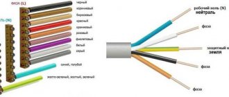
Safety inspectors always pay attention to the arrangement of the so-called re-grounding
The issues of organizing a grounding loop on the consumer side are always given increased attention, since the health of power grid users ultimately depends on the correctness of its arrangement.
According to the requirements of regulatory documents (PUE, in particular), a grounding loop that protects people working on electrical equipment is mandatory under any circumstances. This is explained by the fact that the grounding function installed at the transformer substation, transmitted via a separate protective wire, is very unreliable due to the high probability of a break in the neutral wire (“burning out” of the zero).
Why is re-grounding necessary?
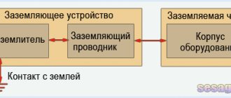
From a technical point of view, re-grounding (RE) is a protective device specially installed on the consumer side that guarantees the safety of people working on the line. It “triggers” in the event of loss of communication with the substation via the neutral or combined wire.
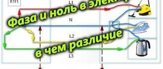
Scheme of re-grounding operation in the event of a zero break on a 0.4 kV overhead line
To arrange re-grounding, it is allowed to use so-called “natural” grounding electrodes, which include:
- metal frames of structures already laid in the soil and having direct contact with it;
- metal protective casings and armor of power cables buried in the ground;
- sections of steel pipes (with the exception of gas mains and oil pipelines);
- railway rails.
Please note: Using ready-made structures already laid in the soil as a re-grounding loop simplifies the installation of the charger and allows you to minimize the costs of its arrangement.
Note that their resistance is not controlled by the user in any way, so its value can change unpredictably at any time. To eliminate this situation, in especially critical cases, artificial grounding structures are installed that have stable technical characteristics.
Re-grounding the neutral wire is one of the ways to organize an artificial system that can duplicate the function of a station switchgear. The last explanation exhausts the question of what re-grounding and how it can be arranged.
Grounding switches
1.Natural
- water pipes laid in the ground (HW)
- metal building structures and foundations securely connected to the ground
- metal cable sheaths
— casing pipes for artesian wells
— gas pipelines and pipelines with flammable liquids
— aluminum shells of underground cables
— pipes of heating mains and hot water supply
The connection to the natural ground electrode must be in at least two different places.
Artificial
Contour
Remote: group and single
Allows you to choose a place with minimal soil resistance.
Traditionally, for artificial grounding conductors, angle steel with a flange thickness of at least 4 mm, steel strips with a thickness of at least 4 mm, or bar steel with a diameter of 10 mm or more are used.
Recently, deep-seated grounding electrodes with copper-plated or galvanized electrodes have become widespread, which are significantly superior to traditional methods in terms of durability and cost of manufacturing the grounding electrode.
A special problem is the creation of high-quality grounding in permafrost conditions. Here it is worth paying attention to electrolytic grounding systems that can effectively solve the problem.
Detailed information about various sealing schemes, calculation methods and consultations can be obtained on the website www.zandz.ru
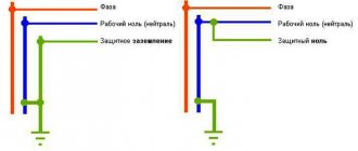
Application of re-grounding in a classic TN system
Re-grounding is a critical element of a comprehensive electric shock protection system. It is used for grounding the neutral protective conductor of PE and PEN electrical networks up to 1000 Volts in a TN system with a solidly grounded transformer neutral.
Classical grounding systems are usually distinguished by the state of their neutral, which can be solidly grounded or isolated. In accordance with this feature, they are divided into two large groups and are designated by the appropriate combination of English letters. “T” stands for ground and “N” stands for neutral, which when written together symbolizes a grounded “zero.” In addition, these systems provide conductors and busbars, designated as PE (separate grounded connection) or PEN - combined working and protective busbar.
Depending on the chosen scheme, the permanently grounded neutral wire N can be either independent from the protective PE conductor, or can be connected to it, forming a PEN bus. In the first case, we get the TN-S system (“Separate” or separate gasket), and in the second - TN-C.
Please note: Here "C" stands for "Combined" or combined.
There is another option when two wires (protective and neutral) are combined on the substation side, and when entering the facility they are divided into a protective conductor PE and a functional bus N. This organization of the consumer protection system is called TN-CS and also requires the grounding of the neutral wire .
Compatible with shutdown devices
To make a person’s work as safe as possible, the PUE recommends the use of RCDs or automatic devices. Such devices can be used in the TN-CS system, when the PEN wire is divided into PE and N conductors. This separation occurs in the incoming electrical panel on the main grounding bus. Moreover, the connection of the main grounding bus is made to repeated grounding or to a PEN conductor grounded at the entrance to the building.
An RCD or automatic circuit breaker reacts to leakage currents in the load. When a leak occurs in the insulation or when humidity increases, leakage currents appear. When a certain leakage current value is exceeded, the RCD de-energizes the protected circuit. The differential circuit breaker de-energizes the circuit when a short circuit occurs in the load.
The use of a secondary grounding device for the neutral wire affects the operation time of circuit breakers. The lower the grounding resistance, the faster and more reliably the circuit breaker will operate, which means the higher human safety in emergency situations in electrical networks.
Application of the TN-C system
The TN-C system was widely used in previously common two-wire networks, which are often found today (mainly in older buildings). From the point of view of the average user, it is characterized by the fact that in this case there is no special grounding contact in the sockets.
TN-C grounding system
In networks designed based on this scheme, the neutral wire is grounded only on the station side (photo above). Therefore, if it accidentally breaks or the so-called “burnout”, all electrical installations and devices connected to the line are completely unprotected. This forces users to personally ground each unit of household appliance used in the house or install an RCD.
Please note: For owners of private and country houses, the conditions in this case are more than favorable, since they can organize re-grounding by installing an external circuit directly on the site.
This system has not been used in modern construction for many years; today it has been replaced by the more efficient TN-S.
Application of the TN-S system
The TN-S system is more advanced in terms of organizing protection, that is, it has a greater degree of electrical safety. This is explained by the fact that it has an “independent” grounded conductor that serves exclusively for these purposes. However, due to the use of additional copper material, the cost of the system has increased significantly. In the case of three-phase power, for example, from a power source (transformer substation), it is necessary to lay a cable containing five wires. These are the three required phases A, B and C, as well as the neutral and protective conductor PE.
Grounding system TN-S
When implementing the TN-C system in electrical circuits, the organization of re-grounding of the neutral wire is also mandatory. It is produced by connecting the neutral conductor to the earth conductor of the protective circuit, installed on the consumer side.
TN-CS system
This scheme was developed to eliminate the shortcomings of the TN-S system and provides for the use of a combined PEN conductor as a common bus, laid only before entering the facility.
Important! Immediately before entering the building, the common bus is divided into two cores (neutral N and protective conductor PE).
This system is a cross between the two protection options already discussed. It is not without the same disadvantages as TN-S, since if the PEN conductor on the line from the substation to the facility is damaged, all electrical appliances installed in it will be under dangerous voltage. For this case, the PUE requires additional protection of the PEN tire from deformation and mechanical damage.
Grounding system TN-CS
In this system, the equipped ground loop is the reconnection of the neutral wire PEN with the charger before entering it into a specific object. In the event of an accidental break of a conductor in the section of the power line “substation transformer - building”, grounding is carried out exclusively through a PE wire.
To do this, at the input to an electrical installation with a voltage of up to 1 kV or in the distribution cabinet at home, the PEN wire must be “split” into two busbars. One of them is used as a working neutral conductor, and the second as a grounding conductor.
The considered approach to the organization of power protection makes it possible to exclude the introduction of induced currents into the power circuits of the house through the effect exerted by the e/m fields of external communications. In addition to this, it reduces the potential on the housings of equipment and household appliances in the event of an accidental break of the N-conductor.
Installation of pin grounding for a gas boiler, on an area with loamy soil
Let us remind you. That for a gas boiler, the required grounding resistance (grounding loop) should not exceed 10 Ohms. in dry weather. In the photographs below, the installation was carried out in damp weather, during rain. Therefore, it was necessary to obtain a resistance reading of no worse than 7-8 ohms. The first pin showed good resistance, within 30 Ohms, which gave hope for obtaining the specified values. The second pin most likely entered the groundwater and the resistance dropped sharply to the required values
However, remembering that in winter the soil freezes to 1-1.5 meters, and also that in summer the groundwater may sink deeper, it was decided to mount a standard set of 4 pins to a depth of 6 meters. Please note that the latest reading at 5.1 ohms is worse than the previous reading at 4.8 ohms. This happens because during installation, the upper part of the soil is broken and a small funnel is formed in which the pin does not come into contact with the ground
Upon completion of installation, after the pin is covered with earth, and also after some time has passed, after the earth has settled, the readings will return to the best values.
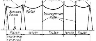
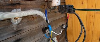
Overhead power lines
On power line (VL) supports, in accordance with the current provisions of the PUE, re-grounding of the PEN conductor laid from the transformer substation is mandatory. This can be explained by the need to increase the electrical safety of personnel working on overhead lines, as well as the creation of conditions for reliable operation of circuit breakers.
Scheme for re-grounding the neutral wire in the power supply system
Please note: The number and frequency of placement of repeated grounding conductors along the route of power transmission lines is determined by the power supply project prepared for it.
PZ must be established in the following places:
- On supports located at the end of the overhead line.
- On poles, immediately before introducing the “air” onto the object.
- Before any branch from the highway, the length of which is more than 200 meters.
Grounding an overhead line support
To install a grounding device, the underground part of an overhead line support is usually used. If it is not enough to obtain the required characteristics, an additional circuit is made. To design the descent from the top of the pillar, wire without insulation with a diameter of 6.0 or 8.0 mm is used. In addition to the PEN wire, all elements of the support structure made of metal must be grounded. According to the requirements of the PUE, the resistance of the repeat circuit should not exceed 30 Ohms.
On poles with street lighting devices, not only SIP wires are subject to mandatory grounding, but also lamp housings and other metal-based parts of the poles themselves. For these purposes, in urban areas with limited deepening capabilities, horizontal stripes are often used instead of typical vertical pins. After their installation, it is necessary to test the equipped system, checking the real resistance of the grounding device using special measuring tools. Without re-grounding the self-supporting wires and city lighting poles, this section of the route is not allowed for operation by the selection committee.
Main types of supports
Wooden
Such structures in most cases will be made of wood, which will not have bark. The length of one log will be from 5 to 13 meters. The thickness of the support can be from 12 to 26 cm. To make such a wooden support less susceptible to rotting, it will be coated with a special antiseptic. Wooden supports can have two types, which include C1 and C2.
Reinforced concrete
Such devices today are made of reinforcement and concrete. They may resemble the appearance of a rectangle or trapezoid. This reinforced concrete device will also be marked with the name CB. After these letters there will also be numbers written that indicate the length of the pillar. For example, you may come across the marking CB-95 and this means that the reinforced concrete pole will have a length of 9.5 meters. In the photo below you can see what a reinforced concrete support looks like:
The following designs can be found on the modern market:
- C.B.
- C.B.
- C.B.
- C.B.
To perform secondary grounding of the PEN conductor, reinforcement is welded on both sides of the pole.
Justification of design decisions
To avoid any difficulties with the approval and delivery of the project, you need to be careful when receiving the design specifications. If equipment that is sensitive to interference is used at the facility being designed, then you must immediately request from the customer or the manufacturer a passport for this equipment, where the need for an independent grounding device must be justified and the required functional grounding resistance must be indicated. Passports (certificates) for the equipment used are attached to the project and serve as justification for design decisions at all stages of project approval.
Independent functional grounding is performed according to the diagram in Fig. 4.
If an independent functional grounding switch is not provided by the equipment manufacturer, then in this case functional grounding must be performed according to one of the schemes (Fig. 2, 3) taking into account the requirements for electromagnetic compatibility. In this case, an isolated functional grounding bus can be installed in a separate grounding box, which prevents simultaneous contact with parts that may be exposed to a dangerous potential difference if the insulation is damaged.
An example of such a functional grounding box is shown in Fig. 6.
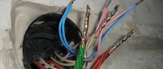
Determination methods
Let's look at ways to determine the neutral and grounding conductors, from very simple to more complex.
The circuit has diff current protection
. If the entire object or branch under study is equipped with differential current protection - a differential current device or an RCD, the task is greatly simplified. You need to connect a control device, for example a lamp with conductors, to the phase and to one of the conductors being tested. If the differential protection does not work, then the lamp is connected to the working zero. If an RCD is triggered when a lamp is connected, you connect it to phase and ground. Everything is quite simple and at the same time check the residual current device in practice.
Before performing such a test, you need to make sure that the diff protection is working by pressing the “test” button on the protective device. It should be noted that the method will work provided that the current through the lamp exceeds the rated differential current of the device. That is, when using an incandescent lamp (an energy-saving lamp is not suitable), an RCD with a leakage current of 10-30 mA will trip. The introductory RCD for a 300 mA leak may not work; for a reliable test, you need to take a more powerful device.
Comparison with grounding contacts of sockets
. This method will work if there is a two-pole circuit breaker at the input that opens the working zero and there are grounded sockets in the room. The input machine should be turned off, thereby we will open any connection between zero and ground. If possible, unplug all appliances from electrical outlets.
Next, you should “ring” with a multimeter in resistance measurement mode the grounding contact of one of the sockets with the contacts being tested. When connected to the neutral wire, the multimeter should show a high resistance; with a ground contact at an unknown point with the ground of the socket, the resistance is almost zero.
In this way, you can at the same time check the correctness of the connected sockets: when the input two-pole circuit breaker is turned off, the neutral and ground contacts should not ring. Well, this is provided that the wiring is initially in good working order and installed correctly.
Climb into the shield
. If it is not possible to implement the previous methods, you will have to go into the “stuffing” of the electrical panel. I think there is no point in reminding about safety precautions here: no one has canceled it. In fact, the method is quite simple: you need to find the neutral conductor going into the room and disconnect it from the switchboard terminals. Then ring with the contacts being tested: the one with whom the call will be made is the neutral conductor.
In the case of a shield, difficulties may well arise when even in the shield it is difficult to distinguish zero from grounding. In this case, you will need current clamps. It is necessary to turn on the voltage and load in the room, and examine unknown conductors in the shield with clamps - where there will be current, there will be a working zero
Please note: the method only works if you know for sure that one of the conductors is zero and the other is ground.
All of the above methods work with both grounding and grounding.
Determine the contacts when connecting an electric stove
. Sometimes it becomes necessary to replace an electric stove socket, but the wiring is from Soviet times or the early 90s, one color. To correctly determine whether an electric stove is zero, a condition is necessary - a two-pole circuit breaker in the input switchboard, which disconnects both phase and zero from the entire apartment.
So, with the power turned on, we determine the phase on the terminals under study for the future socket - we mark this contact and throw it aside, then we don’t need it. Then you need to determine the zero in any socket in the apartment - since the wiring is Soviet, there is no ground there, so the zero will be the terminal on which the indicator screwdriver does not light up.
Now we turn off the power to the entire apartment and use a multimeter to dial the zero of a regular outlet with the two remaining contacts for the electric stove. The contact that rings with the zero of the socket is working, and the one that does not ring is zero (ground). If both contacts ring, you need to look for errors in the electrical wiring. When organizing grounding in Soviet times, it was connected to the “PEN” terminal without any switching devices.
Third party conductive part
A conductor that is not part of the electrical installation is called an extraneous conductive part. A formal example is a metal door handle or hinge.
You can focus on 2 principles according to which parts are selected for connecting to the additional potential equalization bus. The goal is not to make the system overloaded.
- The actual or potential possibility of communication with the “earth”.
- Possibility of potential appearance on a third-party conductive part in the event of an electrical equipment failure during operation.
The table below shows examples of third-party conductive parts that should or should not be connected to the additional potential equalization bus:
| Third party conductive part | Scheme | Connection required |
| A metal shelf mounted on a wall made of non-conductive material. | No | |
| Metal shelf mounted on a reinforced concrete wall. | Yes (potential connection to ground due to wall mounting) | |
| A metal shelf mounted on a wall made of non-conductive material. There is an electrical appliance on the shelf. | Yes (possibility of potential occurrence in case of failure of a device with insulation class I) | |
| Metal bedside table with rubber or plastic wheels on a concrete floor. | No | |
| Metal bedside table with rubber wheels on a concrete floor. There is dirt and dust in the room combined with high humidity. | Yes (potential connection to the “ground” due to pollution and high humidity) |
Issues related to potential equalization in bathrooms and shower rooms are regulated by Circular No. 23/2009.
One of the common questions: can tap water supplied through plastic pipes be a third-party conductive part? The said circular gives the following answer: “...Tap water of normal quality...is not considered as a third-party conductive part.” This means that such a possibility exists, at least due to the significant presence of various ferrous compounds in water. The circular recommends using conductive inserts on taps from water supply risers, connecting them to an additional potential equalization bus.