Third Eye (Part 1)
Part 1 Part 2 Part 3
In Eastern beliefs, it is believed that the “third eye” is a kind of energy center, a part of the brain with the help of which a person gains the possibility of supersensible perception, the ability to see with his eyes closed and to look unhindered into any corner of the universe.
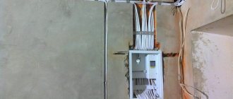
Sites in the city are a potential “minefield”, in which underground utilities and other objects that can be damaged during excavation work carried out by construction and utility services act as mines: power and telephone cables, sewer and gas pipes, etc. d. Damage to underground communications causes losses amounting to millions of rubles: they have to be repaired, the deadlines for completing basic work and commissioning of objects are violated. In such accidents, people are injured and even killed. Even if workers have at their disposal a plan for the location of underground communications, they cannot completely rely on it, since it is not known whether all newly laid communications have been included in it. Before starting excavation work, workers must know for sure that there are no communications in the ground that are not indicated on the plan. It should be noted that there is no universal location method that allows identifying any underground objects - each method has a specific scope and a number of limitations. Therefore, construction and utility companies widely use various equipment to search for underground communications.
Electromagnetic locators (locators)
These are devices for determining the location and damage of underground conductive utilities (cables of electric and telephone lines, metal and polymer, pipelines for liquids and gases reinforced with metal cord or equipped with a signal wire, ducts, etc.) in plan and depth. Today, route finders are popular equipment for maintaining and monitoring the condition of underground communications; they are used to identify illegal tappings, places where pipes are blocked, and detect cables and other fittings underground. Depending on their narrow purpose, devices may have “telling names”: cable detectors, leak detectors, sunroof detectors, flaw detectors, etc.
What are the principles of devices for finding hidden wiring?
The industry produces 3 types of such devices for the modern electrician, which are usually divided as:
- locators;
- electromagnetic field indicators;
- detectors for detecting hidden wiring.
They are created for specific application conditions and have different technical capabilities.
How modern locators work
As an example, let’s look at the operation of the Mastech MS6812 cable tester-router. It is most often used to detect the location of a cable break in closed wiring and consists of two autonomous parts:
- Tone generator cable pressor (Cable tracker), which produces high-frequency signals. Its output is connected to the cable being tested, the route of which must be clarified.
- A cable tracker signal receiver that emits specific sound signals indicating the location of the cable when it is placed in the search area.
Cable tracker tone generator
Cable tracker signal receiver
To connect the generator, first determine the broken core by testing the cable with a digital multimeter. A high-frequency signal is supplied to it and the ground loop.
If you just need to determine the cable route, then connect a generator to the whole core and the ground circuit. In this case, in most cases, external power must be removed from the circuit under test.
The high-frequency radiation is picked up by the tracker's receiver, which produces a clearly audible single-tone continuous whistle. If desired, it can be changed to a two-tone euk, which is better heard in industrial noise conditions. To do this, use the switch built inside the case.
The receiver is led along the route of the laid cable, guided by the sound of the speaker. When the damage is reached, the sound disappears. They are looking for a cliff in this area. The method is very accurate.
To ensure reliable searching, it is recommended to switch the generator to the opposite end of the cable, and then pass the receiver from the opposite side to the same place.
Both the generator and the receiver are powered by their own batteries, which ensures their independent operation.
The locator from Proskit and many other manufacturers works similarly.
More complex cable defects, when it is crushed with a violation of the insulation and cross-section of the cores, but without a break or short circuit, can be determined with an ohmmeter and megohmmeter. However, it will be difficult to determine the exact location of the damage.
Professional route finders, depending on the design, are capable of finding cables hidden in walls up to 40 cm and up to 2.5 meters buried in the ground. But they are expensive.
For home use, it is quite possible to use the budget device Mastech MS6812. It copes well not only with electrical wiring, but also with low-current alarm circuits, video surveillance, antenna devices, computer systems and other similar devices.
Designs of homemade route finders
Home craftsmen with amateur radio skills use their high-frequency generators, directing their signal to damaged wiring. They are tuned to the frequency of a VHF receiver or smartphone and with their help they successfully search for cable defects.
The method requires skills and special equipment, and is not reliable in all cases.
How simple electromagnetic field indicators work
To detect hidden wiring, the property of electric current to propagate an electromagnetic field in the surrounding space is often used. It is detected by indicators of various designs.
The simplest version of such a device is represented by an indicator screwdriver.
Just keep in mind that they are produced with different circuits for capturing the electromagnetic field and the simplest models with an LED or neon bulb and a current-limiting resistor do not have sufficient sensitivity .
Indicator screwdrivers with built-in amplifiers based on bipolar or field-effect transistors or microcircuits are suitable for these purposes. The manufacturer states in the instructions about the function of searching for hidden wiring.
Such a screwdriver is taken by the blade with your fingers, and the back of the handle is applied to the wall.
It is placed in the area under study, moved in different directions, and the route of laying the wire is determined by the strength of the indicator light.
It should be taken into account that the current causing the indicator to glow passes through the human body and he needs to create a closed circuit by touching the slip ring or screwdriver blade with his finger.
Please note that this method is rather approximate and not precise. Its result is affected by:
- the magnitude of the electromagnetic field that is created by the strength of the current. To increase the reliability of the result, it is recommended to apply a large load, on the order of a kilowatt, to the wire cores;
- condition of the wall. A humid environment, wet wallpaper, embedded metal plaster mesh, fittings, even hidden screws can enhance the propagation of the electromagnetic field, distorting the reliability of information;
- increased depth of cable embedding, especially in a dry reinforced concrete wall, can distort the electric field so much that the indicator screwdriver cannot sense it.
A broken wire in the wall cannot be found using this method.
Such a universal device is not difficult to buy, but individual homemade designs have similar search performance characteristics. I will present one of them below.
It includes:
- an antenna wound from turns of thin copper wire and receiving a signal from an electromagnetic field;
- three NPN transistors of the C945 type, assembled in a series cascade that increases the antenna current;
- LED, indicating by its radiation the presence of an electromagnetic field;
- Krona battery powering the circuit;
- current limiting resistor.
A diagram of a homemade hidden wiring indicator is presented below.
As a reference, I show what the pinout of the C945 transistor looks like.
Now many similar circuits have been developed using bipolar and field-effect transistors. It is not difficult to assemble them with your own hands, practically no adjustment is required, but they do not provide high accuracy of readings.
How do hidden wiring detectors work?
The device uses the principle of a metal detector. Its design is based on a scanner that generates signals and receives them after reflection from the controlled environment.
By comparing the characteristics of outgoing and incoming radiation, the density of the controlled environment is determined and assessed. The calculation results are displayed on a scoreboard or digital display in a user-friendly form.
For accurate operation, the scanner body must be lightly pressed against the surface under study with guide rails and evenly guided in one direction.
Most detectors are digital devices that are good at distinguishing metal objects, wires, and voids. More complex products can additionally detect wood and plastic pipes.
Modern, even relatively inexpensive scanner models are endowed with the ability to interact with electromagnetic field radiation and show wires and cables laid in the wall and under voltage.
Locator components
The electromagnetic locator consists of a lightweight portable heterodyne receiver, which provides high noise immunity and sensitivity, making it possible to work in conditions of strong external interference, with a weak signal level, in areas saturated with communications. The receiver has control buttons and a display on which the results of the locator search are displayed. The receiver can be powered by batteries or an electrical cable.
The communications being sought may be energized or de-energized. To search for de-energized communications, a compact generator (transmitter) is used - a source of electromagnetic pulses of a certain frequency. The generator can be connected to the pipe or cable being tested using terminals, or pulses can be transmitted into the communication in a non-contact manner.
To receive signals, antennas are used, one or more, of various designs and spatial orientations, which can also be rotated.
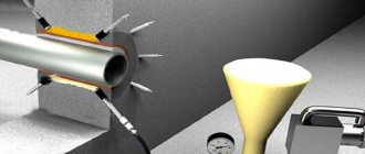
If you need to determine the position of a non-metallic pipe through which a liquid flows, and the pipe does not have a satellite wire, you can use special locators that are equipped with floating probe sensors, which, moving in the pipe along with the liquid, allow you to determine the location of the pipe. Similarly, video head locators with a miniature transmitter are used to locate damage and blockages in pipes. To determine the location of damage to a cable or pipe (and, accordingly, the location of electric current and water leaks), use contact probes buried in the ground, included with the device.
Low-current cables, de-energized power cables, metal pipelines
Communication cables are mostly shielded (including optical cables) and the electromagnetic field generated by moving electrons cannot be detected on the surface of the earth. The same applies to de-energized power cables and metal pipes. To identify such communications, it is necessary to somehow ensure the transmission of a tone signal over them. This can be done using a generator with an induction antenna, with which you can induce a signal in the cable (pipe) without direct access. An induction antenna creates an electromagnetic field around itself. If an electric current conductor enters such a field, eddy currents appear in it, which spread along the cable and lead to the formation of a new field around the conductor. This field is tracked by the receiver. Ideally, to induce a signal in a cable (pipe), it is necessary to place the generator directly above it. That's why:
- an engineer with a generator stands on one side of the site
- the generator is switched on in the mode of contactless connection to the line using an inductor
- another engineer with a receiver stands at a distance of 20-30m from him
- both begin to move in parallel.
If during movement the pipe ends up between the engineers, the engineer with the receiver will be able to record the signal induced by the engineer with the generator. To determine communications using this method, engineers must divide the entire site into squares of 20-30 m and walk each of them along, across and diagonally.
How do locators work?
Electromagnetic locators determine the position of pipes and cables based on the magnetic field existing around the communication being studied. Isolation of communications and soils of various types surrounding communications do not change the appearance of the field. The strongest signal is received when the device is located directly above the communication.
Passive and active modes. If an alternating electric current flows through a communication, it creates a magnetic field and the device can find the communication while operating in passive mode. However, the accuracy of this method is relatively low; with its help, it is difficult to determine the depth of a communication more than 1–2 m and find it if several other communications are located next to it.
If no electric current flows through the communication, then in order for the locator to identify this cable or pipeline, a current must be created in it using a generator. This mode of operation of the device is called active. This method is more accurate than the passive method and allows you to identify an object at greater depths and distances.
When any end or section of the pipe or cable being sought is accessible, for example through a manhole, the generator is connected to the service by means of an alligator clip or induction clamp and a signal is induced therein. Using a generator is very convenient when identifying one of the many nearby communications. The generator is connected to the communication, the inductive current is induced only to this object, and it is easily tracked by a locator at a distance of 1 km or more from the generator connection point. Initially, this method was used to search for defects in electrical and telephone cables. Electric current is supplied to the cable, the operator with the receiver walks along the route, determining its location. At the site of a break, short circuit or other defect, the power of the received signal changes sharply.
When there is no access to the desired communication, using a generator capable of creating a volumetric inductive electric field, a current of a certain frequency (that is, an inductive magnetic field) is remotely injected into the communication, which is picked up by the receiver.
The optimal frequency for effective location depends on the type of soil, the type of pipe or cable, and many other factors. Therefore, locating devices from the world's leading manufacturers can operate at different frequencies, from several hertz to 200 kHz. Moreover, the choice of operating frequency can be either automatic or set manually. Many locator models have only two or three most commonly used operating frequencies: 50 Hz for locating live power cables and 100 Hz for tracing steel pipes under cathodic protection. More advanced foreign models offer a wider range of operating frequencies - from 10 to 35 kHz. This significantly increases the resolution and sensitivity of the device in conditions of an abundance of various communications and strong electromagnetic “noise”.
Receiver. The principle of operation of the receiver is quite simple. It tunes to the frequency of the signal from the communication and, based on changes in signal strength, determines the location of the object. The operating range (distance from the generator to the receiver) for different types of locators ranges from 0.5 m to 20 km with a location accuracy of 10 to 30 cm; the maximum depth at which the device provides route determination is usually up to 10 m. Instrument readings depend on the class of the device, the diameter of the route, the signal power of the generator, the type of soil, and the presence of interference. In particular, large-diameter pipes and cables have a large surface area in contact with the ground and, as a result, signal leakage to the ground. At the same signal strength, its attenuation due to leakage to the ground in large pipes occurs over a shorter distance than in small-diameter communications. There are modifications of devices designed to search for extended objects - pipes, cables, and modifications for detecting small objects, such as manhole covers or pipeline valves.
The devices provide digital processing and optical indication of the received signal. Models with a graphic display usually show digital values of electromagnetic field parameters or, at best, a bar graph of signal strength. It is more convenient to perceive the signal strength “by ear” through headphones, by the tone of the receiver’s sound. When the operator walks along the area in which the communication is located, the receiver generates an audio signal, the tone of the signal becomes higher as the device approaches the communication and begins to gradually decrease as it moves away from it. By marking the places on the soil surface where the signal tone was the highest, the operator marks the underground communication route. An experienced operator can confidently distinguish different types of pipelines and cables by the sound of the device. A number of domestic models of locator finders only have an acoustic indication function. But it is more convenient to work with devices that, along with the audio signal, display traces on the screen, as well as the depth of the communications. Such devices are especially convenient in the case of studying intersecting communications. Mastering such devices does not require special knowledge and skills.
One of the features of the magnetic reconnaissance method is that the strongest signals come from the end points of the object being studied, because the magnetic field lines converge at them. Therefore, a vertically oriented object (even a small steel barrel) is often easier to detect than a horizontally oriented water pipe a hundred meters long. The same effect occurs in the places of connecting joints of the same water pipeline, consisting of separate sections: on the screen of a magnetic prospecting device, a picture appears from a chain of signals of maximum strength, corresponding to the locations of the joints of individual sections of the pipe, from this picture you can determine the route and depth of the object by connecting between are separate points.
Progress in the design of route finders. Modern models of locating equipment have improved protection against electromagnetic interference, making the search for communications much easier. The most complex models of route finders are connected to a laptop computer and, using special software, allow you to obtain complete information about the spatial position of underground and underwater communications in the surveyed area, and also have the ability to work together with GPS/GLONASS receivers for reference to absolute geographic coordinates. Data can be entered into electronic maps and into an electronic project of a construction project.
Currently, the electrochemical method of protecting metal pipes from corrosion is widespread. Therefore, some locators have a CPS function - “cathodic protection search”, which makes finding such communications easy and quick.
Manhole finders. Utilities, and especially organizations that maintain various cables, often need to find manholes hidden under snow and soil. For this purpose, electromagnetic metal detectors of a specific design are used. The device has a sensor - an inductive coil, in which the generator creates a high-frequency electromagnetic field. When the sensor approaches a metal hatch, the frequency of the field changes, which is reflected in a change in the tone of the sound signal in the headphones. More advanced devices, in addition to headphones, are equipped with an LCD display on which search results are presented visually.
Power cables under load and pipelines with cathodic protection
In this case, a fairly large current flows through the cable. Flowing through the cable, the current forms an electromagnetic field, which is easily detected by the receiver in passive search mode. Such cables are looked for first and the probability of finding them is quite high. Most often, this is done by monitoring signals at frequencies of 50Hz (power cables), 100Hz (cathodic protection current of pipelines). To search for a power cable under load on the territory of the site, it is enough to turn on the locator receiver in passive mode and walk along the contour of the area under study. When a cable is detected, you can trace it based on the signal level and mark its location on the site.
Advantages and disadvantages of locators
Simple, portable electromagnetic locators are relatively inexpensive, readily available, can be rented, and are relatively easy to learn to use—and can be used effectively even by inexperienced operators.
The main disadvantage of the electromagnetic location method is that it cannot be used to trace communications that do not conduct electric current: plastic, concrete and ceramic pipes.
This problem is solved by using other devices - ground penetrating radars, which we will talk about in the next article.
Part 1 Part 2 Part 3
→ The procedure for determining the type of cable damage and choosing a method for finding it • Determining the distance to the location of the cable damage • Brief theory from IRK-PRO • Review of damage to cable insulation during the construction and operation of communication lines • Continuity of the cable line with telephone handsets • Measuring the electrical resistance of the circuit (loop) cable • Types of damage to the insulation of communication lines. Methods of calculation and search • Ohmic and capacitive asymmetry • Electrical capacitance. Finding breaks and brokenness • Measurement of coupling attenuation at the near end • Pulse method of cable measurement
The procedure for determining the type of cable damage and choosing a method for finding it
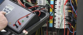
Instruments and methods used
• Telephone handset.
Used for testing and determining the nature of damage.
• Cable device.
This refers to PKP, IRK-PRO or any other class devices capable of measuring insulation resistance up to 30,000 MOhm, the electrical capacitance of cable cores and having bridge circuits for comparing resistances and capacitances.
• Line discontinuity meter or reflectometer
(practically this is the same thing). It can be made as part of the device from the previous paragraph, for example IRK-PRO-Alpha. The pulse cable measurement method is used.
• Crosstalk meter.
For example: IPZ-(the entire series), “Delta-PRO” and the like. They can also be made as part of a cable device.
• Search kit
(router, cable locator). Used to search directly along the cable route. Must use inductive and contact search methods. It consists of at least two blocks: a generator and a search block.
Decide what you will be looking for
Even before approaching the cable terminal, you need to have a clear idea of where the cable begins, where it should end, and whether there are other terminal devices on this cable—parallels. In practice, little-known tie-ins and incorrectly twisted couplings are possible; tens and twenties in the private sector and in rural areas are especially guilty of this.
For cables in operation, an important, albeit indirect proof of the absence of little-known “chemicals” is the same inclusion of cross-connects on both terminal devices. That is, if 0, 3, 5, 8 pairs are turned on at the cable input, then they (0, 3, 5) should be used at the output. However, it is useful to check the presence of power on these pairs, otherwise installers do not always turn those wires that are not used.
For some idea of how all this can be damaged, see the page “Overview of damage to cable insulation during the construction and operation of communication lines”
Handset operation
Ways to find the right pair on the box.
Correct
: you should be informed by technical maintenance (cross) about which pair on the box is damaged. The first method works well on highways and with exemplary certification.
One of its variations is tracking the desired pair starting from the station. For example, knowing what pair number the desired number is in the trunk, we find it in the distribution cabinet and determine which pair it went into distribution or transmission.
Second
associated with cross. The cross-country worker connects to the damaged pair with his device, and you have to look for this inclusion with a handset on the box, connecting the handset to each pair in turn until this cross-country worker answers you.
Third
consists in the fact that you dial the number of the required subscriber (you can use a mobile phone) and use a screwdriver or other conductor to short-circuit all the pairs of the box one by one. When the required pair is short-circuited, the call signal will be interrupted in the handset.
The second and third methods are bad because they trigger an alarm
in neighboring classes and you have a chance to meet armed guys from the authorities.
Determining the type of damage
For measurements, it is necessary to identify broken conductors, conductors with the lowest insulation and conductors with high insulation (clean)
The sequence of actions when determining damage for operation differs somewhat from the same work in construction organizations due to the use of a paired container when connecting a cable line. Builders work with a clean cable, but for operation, it takes half a day to remove power from a 100-pair cable, and then another half a day will have to turn it all on. Add to this that more than 100 subscribers will find themselves without Internet and landline phone service per day.
For use.
Having disconnected the incoming and outgoing cross-connection from the pair under test, we make sure that the damage is in the desired cable (alas, the installer who submitted the damage to the cable must be checked).
If there is voltage on the pair after disconnection (the tube clicks on the ground-core circuit) - this is a message, a violation of the insulation to the other cable pair. Having determined that there is a message in the cable core, find which core it communicates with. To do this, connect the tube to the “ground - damaged core” circuit and short-circuit the remaining pairs of the cable one by one. At the moment the communicating pair is short-circuited, a loud click will be heard in the tube, and if several pairs click, choose the loudest one. Disconnect power from the found pair. The message should disappear or become smaller. Determine by measuring the insulation between the communicating conductors which conductor of this pair communicates.
Congratulate yourself, you have found the cores to measure with bridge circuits.
By definition, there cannot be a message in a single-pair cable (PRPPM, CAPS). Alas, I know a case where this happened - several PRPPMs were spliced together in a homemade coupling and filled with some kind of rubbish, the coupling became numb, and a message appeared on single-pair cables.
The ground of the tube is determined in operation using a supply wire of a different number. If the tube clicks on the power-core circuit when the pair is disconnected, then this is called “ground”. But it is useful for the meter to know that this can also be a message, only the message is not from the supply wire of the adjacent pair, but from the positive one (the supply wire is a minus).
A break is determined by the absence of a station response from the pair at the output end of the cable. Sometimes it is useful to look for broken wires on other pairs of the box, especially if the cable has recently been repaired.
To determine wiretapping (diversity or reduced transient attenuation), the same thing is used with a wiretap, although it only detects a transient of no more than 40 dB. The handset is connected to the pair being tested, and you don’t even have to turn off the power, but only by dialing one digit of the number. Next, alternately shortcut adjacent pairs with a screwdriver. If the pair is poorly protected, then clicks from the short will be heard in the tube, and the pair that is shorted is also affected. For more accurate measurements, instruments of the appropriate class are used.
About wiretapping or raznopark there are pages Measuring coupling attenuation at the near end and Security of pairs and quadruples in communication cables
For construction.
It is easier for builders because they are dealing with unoccupied (clean) cable. Without any disconnections, all its damage can be determined by a simple test. The trick here is to do this on one side or with a minimum number of trips between end devices. So, to determine breaks, you can ground all the conductors at one end of the cable and ensure the presence of grounding at the other end. Message and ground are determined at one end by the same tube or insulation measurement.
When making calls, you should pay more attention to the correct assembly of the cable, and if errors are found in the jointing of the plinths, or there is insufficient resoldering of the cores in the plinths, you should check the transient attenuation between the pairs of the plinth.
An important parameter when accepting a cable for operation is the insulation of the screen (proves the integrity of the sheath)
With a telephone handset you can determine all damage to the insulation and, with some understanding of the processes, even broken pairs (multiple pairs). A little more detail on the page “Dialing a cable line with telephone handsets.”
Continue on Determining the distance to the location of cable damage