Pulse overvoltages often occur in power transmission lines due to atmospheric phenomena, as well as switching processes. Pulse overvoltages due to atmospheric phenomena can also occur in wired communication systems on copper cables, as well as antenna structures of radio communication systems. Sudden voltage surges can destroy the insulation of wires. Also, these phenomena can lead to equipment failure. To combat overvoltages, devices called arresters are used. Their task is to quickly connect the endangered line to grounding, thereby “dumping” the destructive electrical charge. Neither electromechanical systems (relays), nor even microprocessor-controlled devices are capable of replacing simple and cheap arresters, which differ from other “switches” in their high performance.
Installation on a tension garland
First of all, loosen the fastening of the arrester arms. After which the RDIP is separated from the fastener.
The bracket rotates 180 degrees and fits only on one shoulder.
This is done so that the arrester loop can be threaded through the SIP wire without breaking it. Both arms can now be tightened again.
Attach the mounting bracket to the top earring of the garland and set the air gap. It is measured between the central electrode on the arrester and the nearest metal part of the fittings.
If it is not possible to secure the RDIP to the garland, then use suitable fastenings for traverses and slopes.
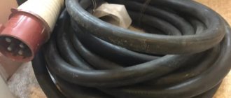
Types of fasteners and distances for the loop arrester on VLZ-6-10kv:
Three-electrode arrester with thermal relay manufactured by CITEL
A more common method when it comes to telecommunications applications is a thermal arrester. These arresters use durable electrodes that can withstand repeated actuation. A thermal relay is switched on in parallel with the arrester. When an arc discharge occurs, the chamber heats up and the thermal relay is activated, shunting the arrester. The voltage across the spark gap drops to zero and the arc discharge stops. After the thermal relay cools down, its contacts open and the spark gap goes into a resting state. Dischargers with thermal relays can withstand up to 10 operations.
Characteristics
The discharge characteristics of RDIP-10 ensure that none of the insulators of all three phases in this circuit overlap, since each of them is protected by a spark gap installed electrically parallel to it and located either directly next to the insulator or on an adjacent support.
At levels of induced overvoltages close to the surge voltage of the arrester, it is possible that the arrester may close on only one support, leading to a single-phase ground fault. The short-circuit current does not exceed 10-20 A, and the loop arrester with a total overlap length of 80 cm is guaranteed to exclude the occurrence of a power arc.
Main technical characteristics
| Voltage class | 10 kV |
| Surface overlap length | 78 cm |
| External spark gap | 2-4 cm |
| Pulse 50% discharge voltage, no more on positive polarity on negative polarity | 110 kV 90 kV |
| Coordination voltage with insulator SHF10-G * | 300 kV |
| Repeated impulse voltage withstood by internal insulation, not less | 50 pulses 300 kV |
| Withstand voltage of industrial frequency, not less dry under rain | 42 kV 28 kV |
| Repeatedly withstand pulse current 8/20 µs, not less | 20 pulses 40 kA |
| Weight | 2.3 kg |
| Service life, not less | 30 years |
Installation
The arrester is designed to protect 6, 10 kV overhead lines from induced lightning overvoltages, which constitute the overwhelming share of the total number of lightning overvoltages that can lead to insulation flashovers.
It is known that the magnitude of induced overvoltages does not exceed 300 kV, and this allows, with proper organization of lightning protection, to exclude the possibility of simultaneous overlap of two or three phases on one support and, accordingly, interphase short circuits. To do this, it is necessary to install one arrester per support with alternating phases, for example, on the first support the arrester is installed on phase A, on the second - on phase B, on the third - on phase C, etc.
With such an installation system, lightning overvoltage induced on the line leads to overlapping of the arresters at different phases of adjacent supports and the formation of a phase-to-phase circuit of the accompanying power frequency voltage current, which includes triggered arresters and grounding resistances of the supports, limiting this current to several hundred amperes, contributing to its extinguishing and preventing the disconnection of overhead lines.
RDIP1-10-IV-UHL1
LONG-SPARK LOOP DISCHARGER MODIFIED RDIP1-10-IV-UHL1
RDIP1-10 in terms of characteristics, principle of operation and purpose does not differ from the arrester RDIP-10-IV-UHL1, being only its structural modification.
The design difference between RDIP1 and RDIP comes down to the changed shape of the loop bend, the details of the fastening unit and the method of ensuring an air gap between the arrester and the wire. The air discharge gap between the RDIP1 electrode and the wire maintains the set parameters regardless of the geometry of the wire in the span and even when the wire slips in the harness on the insulator.
| Name | Meaning |
| Voltage class, kV | 6-10 |
| Conductor | VLZ (SIP) |
| Overvoltage type | Induced |
| Packaging dimensions, cm | 71,5/55,0/43,0 |
| Unit. | PC |
| Quantity per package, pcs. | 10 |
Installation of arrester on suspended insulation PS-70
The arrester is fixed on top of the suspension insulator earring.
The angle of displacement of the arrester element from the wire axis is 30 degrees.
Having set the angle, the bracket is tightened. Next, adjust the gaps. The horizontal distance between the skirt of the upper insulator and the arrester electrode should be approximately 30mm. Once you have it out, tighten all the nuts.
The universal clamp is installed here as close as possible, close to the supporting clamp of the garland.
When installing the operation indicator, ensure its vertical position. At the same time, it should be located under the spherical electrode of the spark gap.
Arresters RMK-20, MCR
Therefore, recently, along with loop-type devices, arresters with the RMK-20 or MCR (Niled) multi-chamber system have become widely used.
It is more compact and easier to install. In terms of application and installation scheme, MCR (RMK-20) is similar to traditional long-spark ones. That is, it is also installed on each support with alternating phases.
What does RMK-20 consist of:
- multi-chamber system - discharge element
- bracket for attaching an insulator or traverse to the reinforcement
- universal wire clamp
It can also be supplemented with an operation indicator.
The design of the bracket is universal and allows you to mount RMK-20 on intermediate and anchor supports SV-105,110,164 with several types of insulation.
Design
Structurally, the SIP clamp consists of:
- Waterproof or sealed housing (the latter is preferable).
- A kind of internal “terminal” made of one or more symmetrical plates with pyramid-shaped spikes, which are located in each of the sockets.
- A fastening system based on the use of a breakaway calibrated screw head.
- Additional clamp release system designed for emergency removal.
Inside the case there is a special lubricant that seals the puncture site, preventing water and air from coming into contact with the wire. This is also facilitated by the specific shape of the teeth.
The SIP clamp is tightened with an ordinary bolt with a 13, or less often 17, head. In total, the system has two bolts - one with a breakaway head, the other a regular one, which, if necessary, can be loosened to pull out the wire and disassemble the entire structure.
There are 2 or 4 sockets for wires. They can be of different diameters, for example, 16–120 and 6–50. Here the first group of numbers is the cross-section of the main wire, the second is the additionally connected one. One of the advantages of SIP clamps is that they (within certain limits) can be adjusted to fit cables of various calibers.
There are two main types of these connectors - with a breakaway head and with a torque wrench, which can be used to set the clamping force. In models with a breaking head, breaking occurs at a force of 9 to 20 Newtons (depending on the model). The same compression force must be achieved when using a modification with a torque wrench, since it is necessary that the teeth pierce the insulation and reliably enter the metal core. In this case, the teeth are significantly deformed - this, in combination with the breaking of the head of the clamping bolt, makes the clamp for SIP disposable. The fact is that, in order to combat the formation of oxides, the plate with spikes in the clamps is made of a relatively soft aluminum alloy. This is its difference from “piercing” terminal blocks.
There is no electrical contact between the connecting screws and the serrated plates. The housings are made from various polymer materials that are UV resistant and often have additional fiberglass reinforcement.
Installation of RVO arresters
Arresters serve to protect the insulation of electrical installations and their electrical equipment from switching and atmospheric overvoltages. Overvoltage refers to any kind of increase in voltage that poses a threat to the integrity of the insulation of an electrical installation.
Switching overvoltages occur when circuits of high inductance or capacitance are disconnected, when short circuits are disconnected, phase breaks and other power supply disturbances. These overvoltages are usually short-lived and can reach 3-4 times the operating voltage of the installation. The most dangerous are atmospheric overvoltages, exceeding the rated voltage by tens and hundreds of times.
Atmospheric overvoltages arise due to the impact on an electrical installation of direct lightning discharges or voltages induced in the elements of the installation during lightning discharges near it. They appear most often in overhead power lines and are dangerous for all elements of the electrical installation associated with the overhead line. The most dangerous are atmospheric overvoltages from direct lightning discharges into a line or substation.
The main means of limiting and protecting against overvoltages are valve arresters. The protective effect of the arrester is to reduce the amplitude of the overvoltage wave to a value that is safe for the insulation of the protected electrical installation. When the voltage increases to certain limits, the spark gaps of the arrester break through and the overvoltage energy is discharged into the ground through a grounding conductor connected to the arrester.
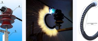
In electrical installations with a voltage of 6-10 kV, valve-type arresters RVO, produced for voltages of 3, 6 and 10 kV, are used mainly for protection against atmospheric overvoltages. They differ in the number of vilitic disks and spark gaps, dimensions and weight, and in appearance - the number of ribs on the porcelain tire.
The RVO arrester consists of three main elements: the spark gap, the operating resistance and the porcelain cover. A single spark gap is formed by two shaped brass electrodes 4, separated by an insulating gasket. A set of spark gaps consists of several consecutive single gaps, which ensure reliable extinguishing of the accompanying current arc. The porcelain cover protects the internal elements of the arrester from the influence of the external environment and ensures the stability of its parameters.
The tires of RVO arresters, depending on their rated voltage, have different heights. The total height of the arrester for voltage 3 kV is 195 mm, for 6 kV - 220 mm and for 10 kV - 345 mm. For all types of arresters for voltages up to 10 kV, the tire diameter is 118 mm. The operating resistance of the spark gap is valite (special mass), the main component of which is silicon carbide.
Single spark gap of an RVO arrester: 1 - brass cover, 2 - resistor, 3 - porcelain cover, 4 - shaped brass electrodes, 5 - micanite washer
In normal mode, the spark gaps are separated from the network by an operating resistance. When an overvoltage occurs, the spark gaps break through and the network is connected to the ground through vilitic disks. At the first moment of breakdown of the spark gaps, the maximum overvoltage will be applied to the vilitic disks and therefore their conductivity will be the greatest. As a result of a discharge to ground, the voltage in the network will decrease and the conductivity of the disks will decrease.
Before installation, all elements of the arresters are carefully inspected. There should be no cracks or chips on the surface of the porcelain cover, and no holes or cracks on the surface of the reinforcement. Tires and other porcelain parts with chips and cracks are not allowed for installation. Damaged reinforced cement joints are restored and covered with moisture-resistant oil paint or enamel. The holes for water drainage in the upper flanges of the working elements are cleaned.
Check the sealing rubber gaskets under the cover with a special curved probe and make sure that the rubber gasket has not slipped and is sufficiently clamped. In a well-sealed arrester, the rubber is elastic and is not pressed through by the probe. There should be no gap between the rubber gasket and the sealing disk (on one side) and the porcelain cover (on the other side) into which the sharp end of the feeler gauge could fit. When lightly shaking and swinging the spark gap at an angle of up to 30° from the vertical, no noise or ringing should be heard inside.
The arresters are supplied assembled and are not opened or inspected during installation. In closed switchgears, arresters are installed in one of the chambers. The installation location is chosen to be convenient and safe for maintenance in order to exclude the possibility of accidental touching of the spark gap, since all parts of the spark gap switched on, except for the grounded base, are energized.
When connecting the busbars to the arrester, the possibility of creating dangerous tensions for it, especially when the temperature changes, is taken into account, and, if necessary, compensating devices are used.
Upon completion of installation, all metal parts and seams of the arrester reinforcement are painted with moisture-resistant paint, and the droppers in the fittings are thoroughly cleaned. The arrester is lifted manually or using hoists onto the supporting structure, to which it is attached with two bolts through the holes in the clamp, and is aligned with level and plumb, placing pieces of sheet steel under the base if necessary. The phase wire is connected to a plate having electrical contact with a multiple spark gap. The grounding conductor is attached directly or through a response recorder to a pin that has electrical contact with the operating resistance. The nuts of the suspension bolt and screw (diaphragm tightening), painted red, must not be unscrewed to avoid damaging the arrester seal.
Issues covered
- What are arresters used for?
- What is the design of RVO arresters?
- How are arresters installed?
- What is the design of the spark gap of the RVO arrester?
8248
Bookmarks
Comment
Comments 0
No one has commented on this page yet.
Write a comment
Installation of RMK-20 on a pin insulator
The arrester is mounted directly on the pin under the insulator by its fastening. Moreover, the bracket should initially be slightly loosened to be able to adjust its position.
The angle of displacement of the arrester relative to the wire axis should be within 30 degrees.
The distance from the bracket to the lower skirt of the insulator is also adjustable - 30mm. The best way to do this is using a template.
After adjustment, the bracket bolts can be tightened. Tightening force 25 Nm.
There must be an air gap of a fixed size between the SIP-3 wire and the RMK-20 tip. To do this, a universal clamp is mounted on the wire.
For VLZ with SIP-3 wires, the clamp has a piercing spike.
The universal clamp is tightened in a horizontal position.
Next, to adjust the air gap, slightly unscrew the bolt fastening and move the arrester in the desired direction. I can simply set the size of the air gap between the end spherical electrode and the clamp on SIP-3 according to the template.
This gap must be within the following limits:
for VL-6-10kv - 40-60mm
for overhead line-20kv - 50-70mm
Please note that bending the arrester without loosening its bracket is prohibited. Otherwise you may damage the internal reinforcing element.
Installation of RDIP on 6-10 kV overhead lines with pin insulators
Secure the arrester with a clamp to the insulator pin.
To set the gap between the SIP-3 wire and the arrester, you can manually change the bend of the loop. Next, a universal or biting clamp is mounted. It is placed on the inside of the loop.
The air gap is adjustable. Its value for VLZ-6-10kv:
- 40mm from SIP wire
- 20mm from universal clamp
Installation of arrester RDIP-10 on supports of various types
Overhead line > Installation of long-spark arresters RDIP at VLZ-10kV
Layout diagram of long-spark arresters RDIP-10 on a single-circuit overhead line 10 kV on anchor gypsum supports (Mounting P2), 23.0067-10
Installation of arrester RDIP-10 on anchor-type supports on the outermost wire (Mount P2) 23.0067-11
| Pos. | Designation | Name | Number | Weight, kg |
| 1 | TU 34130-023-45533350-2002 | RDIP-10 | 1 | 2,3 |
| 2 | 23.0067-20 | 1 | 5,3 | |
| 3 | L56-97 | Clamp X51 (X1)* | 1 | 1,1 (1,2) |
| 4 | TU34-13-10273-88 | Clamp PS-2-1 | 1 | |
| 5 | GOST 5915-70 | Nut M12 | 2 | 0,02 |
| * Clamp X51 is used for reinforced concrete. racks SV110, S112; X1 - for SV105. |
Installation of the RDIP-10 arrester on anchor-type supports on the middle wire (Mount P2) 23.0067-12
| Pos. | Designation | Name | Number | Weight, kg | Note |
| 1 | TU 34130-023-45533350-2002 | RDIP-10 | 1 | 2,3 | |
| 2 | 23.0067-20 | Traverse TM 101 | 1 | 5,3 | |
| 3 | L56-97 | Clamp X51 (X1)* | 1 | 1,1 (1,2) | |
| 4 | TU34-13-10273-88 | Clamp PS-2-1 | 1 | ||
| 5 | GOST 5915-70 | Nut M12 | 2 | 0,02 | |
| * Clamp X51 is used for reinforced concrete. racks SV110, S112; X1 - for SV105. |
Installation of arrester RDIP-10 on single-circuit corner intermediate supports (Mount P3) 23.0067-13
| Pos. | Designation | Name | Number | Weight, kg | Note |
| 1 | TU 34130-023-45533350-2002 | RDIP-10 | 1 | 2,3 | |
| 2 | GOST2590-88 | Circle 22 L=120 | 3 | 0,36 | |
| 3 | GOST 5915-70 | Nut M12 | 2 | 0,02 |
Installation of arrester RDIP-10 on corner anchor supports in phase A (Mount P4) 23.0067-14
| Pos. | Designation | Name | Number | Weight, kg | Note |
| 1 | TU 34130-023-45533350-2002 | RDIP-10 | 1 | 2,3 | |
| 2 | GOST2590-88 | Circle 22 L=240 | 1 | 0,72 | |
| 3 | GOST2590-88 | Circle 22 L=250 | 1 | 0,75 | |
| 4 | GOST 5915-70 | Nut M12 | 2 | 0,02 |
Installation of arrester RDIP-10 on corner anchor supports in phases B, C (Mounting P1 and P4) 23.0067-15
| Pos. | Designation | Name | Number | Weight, kg | Note |
| 1 | TU 34130-023-45533350-2002 | RDIP-10 | 1 | 2,3 | |
| 2 | GOST2590-88 | Circle 22 L=240 | 1 | 0,72 | |
| 3 | GOST2590-88 | Circle 22 L=250 | 1 | 0,75 | |
| 4 | GOST 5915-70 | Nut M12 | 2 | 0,02 |
Installation of arrester RDIP-10 on double-circuit anchor-type supports (Mount P5) 23.0067-16
| Pos. | Designation | Name | Number | Weight, kg | Note |
| 1 | TU 34130-023-45533350-2002 | RDIP-10 | 2 | 2,3 | |
| 2 | 23.0067-21 | Traverse TM 102 | 1 | 5,3 | |
| 3 | L56-97 | Clamp X51 | 1 | 1,1 | |
| 4 | TU34-13-10273-88 | Clamp PS-2-1 | 1 | ||
| 5 | GOST 5915-70 | Nut M12 | 4 | 0,02 |
Installation of arrester RDIP-10 on double-circuit corner intermediate supports (Mount P6) 23.0067-17
| Pos. | Designation | Name | Number | Weight, kg | Note |
| 1 | TU 34130-023-45533350-2002 | RDIP-10 | 2 | 2,3 | |
| 2 | GOST2590-88 | Circle 22 L=120 | 2 | 0,36 | |
| 3 | GOST 5915-70 | Nut M12 | 4 | 0,02 |
Installation of arrester RDIP-10 on angular intermediate supports (Mount P7) 23.0067-18
| Pos. | Designation | Name | Number | Weight, kg | Note |
| 1 | TU 34130-023-45533350-2002 | RDIP-10 | 1 | 2,3 | |
| 2 | GOST2590-88 | Circle 22 L=120 | 2 | 0,36 | |
| 3 | GOST2590-88 | Circle 22 L=180 | 1 | 0,54 | |
| 4 | GOST 5915-70 | Nut M12 | 2 | 0,02 |
Installation of arrester RDIP-10 on elevated corner intermediate supports (Mount R8) 23.0067-19
| Pos. | Designation | Name | Number | Weight, kg | Note |
| 1 | TU 34130-023-45533350-2002 | RDIP-10 | 1 | 2,3 | |
| 2 | GOST2590-88 | Circle 22 L=120 | 2 | 0,3 | |
| 3 | GOST 5915-70 | Nut M12 | 2 | 0,02 |
All pages of the section on WebsorIntroduction Installation of arrester RDIP-10 on a VLZ-10kV pole and their mounting diagrams Selection of types of fastening to supports for various projects Installation of arrester RDIP-10 on supports of various types Cross-arms for mounting arrester RDIP-10
Installation of arrester on tension insulation
If there is a pin insulator on the VLZ-10kv anchor support, which is used to fasten the cable, then the arrester is mounted on it.
If there is neither a pin nor a supporting one, then the RMK-20 is placed on the earring of the PS-70 disc-shaped suspension insulator. In this case, the element chamber should be directed downward. The angle of displacement relative to the wires is still the same - 30 degrees.
On the wire, opposite the spherical tip, immediately behind the tension clamp, a universal or operation indicator is fixed.
At the same time, it should not be at a distance closer than 50mm from the edge of the insulator skirt.
The air gap to the element of the RMK-20 itself is here in wider values - 50-100mm.
At this point, the installation of the RMK-20 arrester can be considered complete. All that remains is to tighten all the bolts on the fasteners and re-check the standardized distances.
Spark gap device
The design of a typical spark gap contains the following main elements: a sealed chamber filled with gas, electrodes, and an arc extinguishing device.
When the voltage on the electrodes is not higher than the threshold value, the spark gap is at rest. Internal resistance (up to 1 GOhm) in this mode can be considered infinitely large.
When the voltage increases above the threshold value, a glow discharge first appears on the electrodes in the gas, as a result of which the voltage at the terminals drops to 80 V. At the same time, the gas heats up and the current through it increases, which quickly leads to the occurrence of an arc discharge when a plasma channel is formed inside the device low resistance. After transition to this state, a significant current flows through the spark gap (up to 150 kiloamperes), and the voltage at the terminals drops to a value of about 20 V.
Is it permissible to lengthen
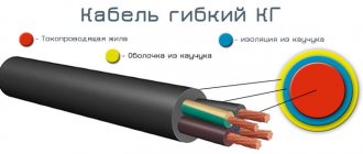
It is more convenient to work with a long wire, but it increases the resistance of the conductor and, accordingly, an additional voltage drop occurs across it.
To provide the required current, the device must be switched to maximum load mode, which causes rapid wear of the device. It is possible to lengthen the cable, including the return wire, but replace it with a thicker one with a larger cross-section.
Then the losses on the conductor will not change, but the mass of the cable will increase. Since the resistivity is constant for a particular metal, doubling the length of the conductor will require doubling the cross-sectional area.
In this case, it is necessary to correctly connect the plugs and terminals to the cable. They must be connected by crimping or soldering followed by insulation.
There is no clear unambiguous prohibition on lengthening from manufacturers. Special requirements for ensuring current are placed on electrode holders. However, many experts do not recommend extending the cable, stating that the device may fail, and the manufacturer will void the warranty.
Rolling out SIP-3 wire
A power roller of a slightly different design with a bandage tape is attached to the initial anchor support. If the intermediate crossbars do not have loops or a hook from which the roller could be hung, then devices with bandage tape are used everywhere.
Technical characteristics and brands of mounting rollers from Ensto, Sicam, Niled, KVT:
Ensto
Sicam
Niled
KVT
Rolling out from the drum should be done in such a way as to prevent the wire from touching the ground and the support posts. A leader rope is used for this. It must be made of synthetic rope with a minimum diameter of 6mm.
A standard drum from Ensto ST204.2060-0030 easily fits 1100 m of such cable.
Basic requirements for the rope:
high mechanical breaking load
low susceptibility to stretching
UV and moisture resistance
dielectric
If the length of the cable is not sufficient, then it can be spliced together with special connecting brackets.
The ST204 motorized winch is secured to the final anchor support. A drum with a leader rope is placed on it.
The motor winch provides ease of installation and reduces the total operating time several times.
The portable sheeting machine is installed using a belt or chain banding device.
The leader cable is first pulled through the mounting roller on the final support, and then sequentially through the intermediate supports, pulling it along the grooves of the pin insulators.
The rope stretched across the entire anchor section is connected to the wire using a mounting stocking. The leader rope is simply tied with a compact knot directly to the loop of the mounting stocking. At the same time, unlike low voltage wires SIP-4, a swivel for SIP-3 does not need to be used.
The edge of the stocking is wrapped with turns of electrical tape to prevent it from slipping.
One of the installers uses the radio to give a command to the other, who controls the winch, to turn it on. He must also constantly monitor the passage of the cable-to-wire connection along the entire line. And if a wire gets stuck, immediately give the command to stop the winch.
The SIP wire must be pulled evenly, without jerking, at a speed of less than 5 km/h. When rolling out, do not allow the wire to touch the ground and support posts.
How to distinguish an original RDIP-10 arrester from a counterfeit one?
The main differences are as follows.
There is no marking on the PIGR shell itself; The design of the bracket is different - the counterfeit one is welded, ours is stamped; end cap (aluminum cap at the end of the product) - ours is in the form of a glass, one-piece, obtained by extrusion, while the counterfeit is made of an aluminum pipe and capped on one side with an aluminum stopper; the outer surface of the PIGR is heavily worn, a breakdown of the PIGR when checking the electrical strength of the insulation; spring electrodes on original arresters and flat electrodes on counterfeit ones; on counterfeit RDIP nameplates there are “Streamer”, but without the batch number and product number; As a rule, in invoices and accompanying documents, counterfeit arresters are marked using non-Roman, Arabic 4s, i.e. RDIP-10-4-UHL1.
Preparation for installation
Before installation, be sure to carry out an external inspection. The discharge element must be free of cracks, cuts, mechanical dents, etc. Try to bend the element using light force. It should be sufficiently elastic and immediately restore its original shape.
If the kit includes response indicators, check the integrity of the opaque glass bulb.
Initially, the arrester is supplied disassembled. Therefore, it must be assembled into a single structure. Use a bolt with nuts and washers to connect the bracket and the multi-chamber system.
Tubular arrester
The tubular arrester is a tube made of durable material. The material itself is various polymers. The most common of them is polyvinyl chloride. PVC is able to withstand temperatures suitable for this type of arrester.
Two electrodes are placed in the tube (Fig. 1). One is connected to the protected element, and the other is grounded. The operating principle of a tubular arrester is quite simple.
When the breakdown voltage occurs, a spark is formed, which ionizes the air. The air becomes very hot and gases are released on a massive scale.
Intense gas generation extinguishes the phase voltage arc. This arc extinguishing device is called longitudinal blast. To allow gases to escape outside, there is a hole in the arrester.
A gas spark gap differs from an air spark gap only in that its body is filled with an inert gas (argon or neon). Unlike an air spark gap, in a gas spark gap the arc formed by phase voltage is extinguished by inert gases.
In modern electronics, tubular arresters are ubiquitous. They are simple in design and reliable. The breakdown voltage of air dischargers is low, so such arresters are not used in higher voltage equipment.
Figure 3. Tubular arrester
Disposable and self-restoring arresters
A disposable spark gap will not be able to protect insulation and equipment from repeated lightning. After completing its action, it represents a jumper with a resistance close to zero. In power supply networks, such a jumper triggers a protection that cuts off the power supply. Communication in telecommunication networks is interrupted, which triggers an alarm. After receiving a signal about a power outage or interruption of communication, a specialist comes to the site to replace the disposable arrester.
The simplest option for implementing a disposable spark gap is electrodes inside the chamber, made of metal that melts under high temperature. A more complex option is a jumper attached to the chamber wall with a drop of easily melting metal. During an arc discharge, this drop melts and a jumper connects the electrodes. You've probably already guessed that a disposable spark gap is not the best solution for protecting electrical lines and devices.
A self-healing spark gap is capable of returning to its resting state a limited number of times. Sometimes such a surge arrester is used in conjunction with a trip counter, which allows one to estimate the lightning load and the expected service life of the device.
Valve arresters.
The valve gap consists of a set of repeatedly repeating spark gaps and nonlinear resistances.
Resistors consist of a set of vilitic disks. Vilit is a baked mixture of calcium carbide and liquid glass. Compared to tubular and gas arresters, valve arresters have a higher breakdown voltage.
We invite you to read Truth or Myth: We analyze popular ways to strengthen the immune system
Figure 4. Valve arrester.
Unlike the valve arrester device, the magnetic valve arrester device includes a set of ring magnets.
The principle of operation of a magnetic valve arrester is slightly different. When a phase voltage breaks down, an arc is formed. Under the influence of the magnetic field of the magnets, the arc begins to rotate, thereby extinguishing the arc.
Design features of the long-spark gap RDIP-10-4 UHL1
The main element of the device is a metal spark gap bent into a loop, covered with a layer of polymer material (high-density polyethylene). The ends of the rod are placed in the fastening clamp, which makes it possible to attach the arrester to the insulator pin of the support or to another element of the overhead line. On top of the loop insulation in the middle part of the device there is a metal tube, opposite which a clamp is attached to the overhead line wire. An air-spark gap is formed between these elements. In the event of an induced lightning impulse, the gap is broken and a voltage is applied to the insulation between the potential loop rod and the metal tube. A sliding discharge passes along the surface of the insulation of the spark gap from the tube to the clamp, which does not turn into a power arc.
Disadvantages of RDIP
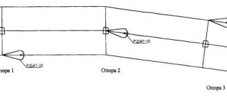
However, a long period of operation shows that this type of protection does not always fully fulfill its functions. On some overhead lines, the number of single-phase short circuits may even increase.
In addition, tests confirm that RDIP cannot always protect the insulation on adjacent supports. That is, on the next two, where it is not installed in this phase. Here, much will depend on the brand of insulator, the distance between the supports and the level of overvoltage.
ShF-20 can even block insulators.
Here's a visual test in the lab:
Installation of supports for VLZ-10kv
The SIP-3 wire can be mounted both on new supports and on existing ones, instead of bare AC-50-70-95-120 wires. Naturally, with the replacement of all load-bearing, fastening fittings and insulation. Replacing an old 10 kV overhead line with a new overhead line with SIP-3 wires is called reconstruction.
Both reconstruction and new construction must be carried out according to the project.
Most often, the installation of a new overhead line begins with the installation of anchor supports. Even before the anchor support post is raised, the required number of traverses are secured to it on the ground.
To prevent corrosion, and also because the line must be maintenance-free, it is necessary to use galvanized crossbars. Otherwise, in a few years you will have to re-climb each support and repaint the faded cross-arms to protect them from rust.
The traverse is immediately grounded. This is done by connecting a die clamp and a steel rod with a diameter of at least 10 mm (section 78.5 mm2) to the grounding outlet at the top of the support.
On reinforced concrete supports, both welded and bolted connections are allowed. On wood, it is recommended to use dies first.
On multi-post anchor supports, the number of grounding descents must be at least two. As such, you can use elements of longitudinal reinforcement of reinforced concrete racks SV-105-110.
All metal structures here (the strut fastening, the traverse itself) are grounded from above, through the grounding outlet. There is no need to make a separate descent made with a rod or strip, directly along the body of the support to the ground.
It is advisable not to screw the insulators onto the traverse onto the ground until the support is installed, in order to avoid accidental damage and damage during installation with special equipment. A partially equipped rack is installed at the desired point using a truck crane or a drill crane machine.
Then one or two struts are installed. Their number depends on the route layout and is determined by the project.
The support must be buried at least 2.3-2.5 meters. After this, intermediate supports are installed.
How does the arrester work?
Arresters are needed to protect overhead power lines (OHT) from lightning effects, including the consequences of direct lightning strikes. Overhead lines are long electrical circuits consisting of wires and auxiliary devices that transmit and distribute electricity. On any long line there are several areas that require increased attention. For example, if the line passes through a hill, a water barrier, an area of abnormal thunderstorm activity, or is located on the approach to substations. Installation of 10 kV arresters produced by NPO Streamer JSC ensures the limitation of lightning overvoltages on the line, thereby protecting the equipment of electrical networks and installations from emergency shutdowns and damage after lightning strikes. Every time lightning impacts power equipment, resources are depleted and the equipment ages significantly. Thus, economic losses from the impact of lightning on energy systems are reduced. Practice shows that the costs of lightning protection measures are several times lower than the costs of eliminating the consequences of lightning strikes.
Order and delivery
We work with legal entities, payment for goods is only by non-cash payment.
To buy an RDIP-10-IV UHL1 arrester (NPO Streamer), you just need to call or write or send a request through the form on the website.
Receipt of goods Pickup
| In order to independently pick up products from the warehouse, the recipient must have a power of attorney and a passport. Warehouse opening hours: Mon–Fri: 8:00 to 17:00 |
Our delivery to the recipient's warehouse
| We are ready to deliver your order to the address you specify in any region of the Russian Federation. In Moscow: transportation of cargo weighing up to 5 tons to the buyer’s warehouse – 1,500 rubles. VAT included. In Russia: the cost is calculated depending on the weight, volume of the goods and the location of the recipient. |
Transport companies
| Delivery to the terminal of any transport company in Moscow is free. It is recommended to order wooden packaging for fragile goods. |
Do you produce surge arresters?
No, we do not manufacture surge arresters.
There are two types of devices supplied to the world market for lightning protection devices: arresters and arresters of our production. We just don’t take spark gaps into account. In the Russian Federation, they also continue to produce tubular and valve-type arresters, although, by all accounts, they have already outlived their usefulness, for sure for lines of 35 kV and above. There are new developments, for example in China, these are various designs-combinations of surge arresters, “horns” and even tubular arresters. But all of them are at the research stage and are not commercially available.
There are many devices based on surge arresters, each manufacturer tries to bring something different, but the base is the same - varistors. And varistors require careful handling and have a certain throughput.
Reading schematics: arresters and fuses
Arresters, like fuses, protect electrical equipment from damage that may occur as a result of a short circuit. Arresters protect the insulating coating of electrical installations from destruction by overvoltages, in some cases external, for example, lightning, and in other cases internal, occurring inside the installation itself (switching overvoltages). The main task of fuses is to disconnect the place where a short circuit (short circuit) has occurred.
Circuit breakers. The figure below illustrates the fuse designations. No. 1 – this designation can be used in any case. There are circuits in which the fuses are designated Nos. 2-3 - slow-fuse fuses; No. 4-5 - refractory fuses; No. 6 – high-speed fuses.
Typically, fast-blow fuses are used in rectifier installations to protect semiconductor rectifiers. In communication devices, due to the fact that the lines are long and the cross-section of the conductors is very small, the value of the short-circuit current is very limited. For this reason, conventional fuses are not used in such installations; they are replaced with thermal safety coils - No. 7. Thermal coils are also used in alarm devices.
In modern installations, fuses are combined with either switches or connectors.
Arresters. The general designation of a two-electrode spark gap is illustrated in figure No. 8. The general designation of arresters (not taking into account its type) is given under number 11. To indicate the type, the following designations are used: No. 9 – ball arrester; No. 10 – horny; No. 12 – tubular arrester; No. 13 – valve arrester (this indicator has been canceled, but it can be found on some old circuits); No. 14 – valve arrester; No. 16 vacuum discharger, No. 17 two-electrode ion discharger with gas filler. Gas filling in the diagrams is indicated by a bold dot inside the image of the cylinder.
To prevent massive breakdown of insulation and electric shock to a person when the insulating coating between the high and low voltage windings of the transformer is damaged, breakdown fuses No. 15 are used. This type of fuses is connected between the neutral of the low voltage windings and the ground - if the winding is connected in a star. If it is a triangle, then it is between one of the phase wires and the ground.
Arc horns
Initially, a system of arc protection “horns” was widely used. When an arc and a single-phase fault were artificially converted into a two-phase short circuit with a guaranteed shutdown of the power line.
However, this system has significant disadvantages:
- it does not protect the insulation from overvoltage
- does not prevent line disconnection, but rather contributes to it
Meanwhile, for lines with an isolated neutral, a single-phase fault is not an emergency mode requiring immediate shutdown.
In addition, the “horns” periodically burn and require replacement.
And when the overhead line passes through plantings and forest clearings, interphase short circuits are possible due to contact with branches.
Therefore, to protect overhead power lines of medium voltage 6-20 kV from lightning overvoltages, special devices began to be used - long spark gaps of the loop type RDIP.