Electrical laboratory » Electrical laboratory services » Ground loop resistance standard
Certificate for the grounding loop of a gas boiler
Types of electrical laboratory measurements
Frequency of measurements by the electrical laboratory
Very often, power engineers argue about what should be the norms for spreading the ground loop current? What is the value of the ground loop resistance? What is the permissible ground loop resistance? As a rule, in such disputes you can hear different numbers, some call 4 Ohms, others say 20 Ohms, some experts say that the resistance of the grounding circuit is not standardized. So what should the norms be and why is there such confusion?
What are the tests?
Let me start by explaining what tests there are. The electrical laboratory carries out acceptance or operational tests. Acceptance tests are carried out after the installation of a new electrical installation is completed, after the electrical installation is installed and put into operation, from this moment operational tests begin. Accordingly, acceptance tests are carried out only once, after completion of electrical installation work, and operational tests are carried out periodically, during operation.
And so, there are acceptance and operational tests. Acceptance tests are regulated by the Rules for the Construction of Electrical Installations (PUE), and operational tests are regulated by the Rules for the Technical Operation of Consumer Electrical Installations (PTEEP).
1.7.55
For grounding in electrical installations of different purposes and voltages that are geographically close, one should, as a rule, use one common grounding device.
A grounding device used for grounding electrical installations of the same or different purposes and voltages must meet all the requirements for the grounding of these electrical installations: protecting people from electric shock when the insulation is damaged, operating conditions of networks, protecting electrical equipment from overvoltage, etc. during the entire period of operation.
First of all, the requirements for protective grounding must be met.
Grounding devices for protective grounding of electrical installations of buildings and structures and lightning protection of categories 2 and 3 of these buildings and structures, as a rule, should be common.
When installing a separate (independent) grounding system for working grounding under the operating conditions of information or other equipment sensitive to interference, special measures must be taken to protect against electric shock, preventing simultaneous contact with parts that may be exposed to a dangerous potential difference if the insulation is damaged.
To combine grounding devices of different electrical installations into one common grounding device, natural and artificial grounding conductors can be used. Their number must be at least two.
What are PUE standards
PUE norms are a collective group of special normative legal acts that were written under the USSR by the Ministry of Energy - rules for the design of power installations. These rules for electrical installations contain a description of how to properly create electrical wiring in residential buildings, factory premises and other structures; they have a description of various devices, as well as the principle of their construction. PUE includes the conditions for laying communications of electrical installations, components, requirements for certain systems and their individual elements.
Very often, PUE standards are used when installing electric lighting in buildings, various premises, as well as streets, towns, and the territories of certain institutions or enterprises. They contain conditions for the installation of ultraviolet irradiation in health-improving structures, advertising with lighting devices, and more. When laying wiring in buildings, refer to a specific section of the PUE standards.
In separate sections you can find recommendations on how to make a grounding loop, how to install electrical protective devices, and other rules for the operation of various electrical equipment. More detailed and precise information about the conditions for using such equipment is written in the Rules for the Technical Operation of Consumer Electrical Installations (PTEEP).
Today, if you follow all the rules of the PUE for installing and connecting different types of wiring, laying a grounding loop or other technical solutions, the cost of such work will be very high. For this reason, these standards are followed superficially, observing only the most important instructions, and for others they try to find an alternative solution. Despite the high cost, these rules make it possible to effectively protect a building of any type from various negative factors.
1.7.54
For grounding electrical installations, artificial and natural grounding conductors can be used. If, when using natural grounding conductors, the resistance of the grounding devices or the touch voltage has an acceptable value, and the normalized voltage values on the grounding device and the permissible current densities in natural grounding conductors are ensured, the implementation of artificial grounding conductors in electrical installations up to 1 kV is not necessary. The use of natural grounding conductors as elements of grounding devices should not lead to their damage when short-circuit currents flow through them or to disruption of the operation of the devices with which they are connected.
Methods and methods for measuring indicators
There are several ways to check grounding. There are special instruments for measuring ground resistance parameters. Let's consider the main measurement methods using electrical equipment:
- current clamps;
- ammeter-voltmeter;
- specialized devices.
It is possible to measure resistance using current clamps. When using them, there is no need to disconnect the device itself and use additional electrodes. The process of how to measure grounding is quick and quite accurate. Let's look at the principle of operation of current clamps in more detail.
Alternating current passes through the secondary winding. To make the calculation, you need to divide the resulting value of the conductor EMF by the numerical determination of the current. When measuring at home, mites S.A 6412, S.A 6415, S.A 6410 are used.
Let's look at how to check the ground loop using an ammeter-voltmeter. You will need to assemble an electrical circuit. In it, the current will move through the ground electrode being tested and the additional electrode. It is necessary to add a potential electrode to the circuit. Its purpose is to detect voltage surges. The distance from the potential electrode to the current electrode and the ground electrode is the same, it is in the range of harmless potential and affects the grounding. To obtain the resistance value, you need to use Ohm's law to calculate using the formula R=U/I.
For testing and checking resistance parameters at home, a multifunctional multimeter will not be convenient. In this case, it is better to use the following resistance meters:
- ISZ-2016;
- MS-08;
- F4103-M1;
- M-416.
Let's look at how to measure grounding resistance using the M-416 device as an example in more detail.
1.7.54
For grounding electrical installations, artificial and natural grounding conductors can be used. If, when using natural grounding conductors, the resistance of the grounding devices or the touch voltage has an acceptable value, and the normalized voltage values on the grounding device and the permissible current densities in natural grounding conductors are ensured, the implementation of artificial grounding conductors in electrical installations up to 1 kV is not necessary. The use of natural grounding conductors as elements of grounding devices should not lead to their damage when short-circuit currents flow through them or to disruption of the operation of the devices with which they are connected.
How it works
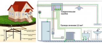
To make it clear to everyone why grounding loops are needed, let’s look at the principle of operation of a composite structure. The protective ground loop works as follows:
- Due to high-quality installation of grounding conductors and good contact with the ground, the metal distributed system provides ideal conditions for emergency currents to flow into the ground.
- Thanks to this, the potential dangerous to humans that appears on the body of electrical equipment in emergency mode (when the insulation of a phase wire is broken, for example), is sharply reduced.
- Reliable flow of current into the ground is ensured by the low contact resistance of the ground electrode, which is part of the protective circuit.
The appearance of significant emergency currents leads to the operation of protection devices installed in the supply circuits (both circuit breakers and fuses).
As a result, the power supply is completely turned off, preventing possible negative consequences. When connecting a ground loop, the main focus is on creating conditions that ensure effective contact of both pins and strips with the ground.
1.7.93
It is not recommended to connect the external fence of electrical installations to a grounding device.
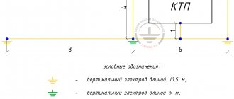
If overhead lines of 110 kV and higher depart from the electrical installation, then the fence should be grounded using vertical grounding conductors 2-3 m long, installed at the fence posts along its entire perimeter every 20-50 m. Installation of such grounding conductors is not required for a fence with metal posts and with those posts made of reinforced concrete, the reinforcement of which is electrically connected to the metal links of the fence.
To exclude electrical connection of the external fence with the grounding device, the distance from the fence to the elements of the grounding device located along it on the internal, external or both sides must be at least 2 m. Horizontal grounding conductors, pipes and cables with a metal sheath or armor and other metal communications must be laid in the middle between the fence posts at a depth of at least 0.5 m. In places where the external fence adjoins buildings and structures, as well as in places where internal metal fences adjoin the external fence, brick or wooden inserts of length not less than 1 m.
Power supply to electrical receivers installed on the external fence should be supplied from isolation transformers. These transformers are not allowed to be installed on a fence. The line connecting the secondary winding of the isolation transformer with the power receiver located on the fence must be insulated from the ground to the calculated voltage value on the grounding device.
If it is impossible to carry out at least one of the indicated measures, then the metal parts of the fence should be connected to a grounding device and potential equalization should be performed so that the touch voltage on the outer and inner sides of the fence does not exceed permissible values. When making a grounding device according to the permissible resistance, for this purpose a horizontal grounding conductor must be laid on the outside of the fence at a distance of 1 m from it and at a depth of 1 m. This grounding conductor should be connected to the grounding device at at least four points.
Checking protective grounding parameters
In addition to the obvious components of the protective “earth” system: such as a contact block, wires going to electrical installations, connection to a circuit in the ground, the earth itself plays an important role in providing protection. Accordingly, you need to make sure of the following:
- Between all elements of the circuit (pins, connecting bars, conductor into the room to the terminal block) there is a reliable electrical connection with minimal resistance.
- The voltage applied to the circuit (in the event of an accident) spreads across the physical ground with maximum current. This is only possible with good contact between the metal and the ground.
- The physical conditions of the terrain (ground) can ensure reliable contact even under poor (in terms of electrical current) conditions. Namely, drying out of the soil, cracking of the earth in the places where ground electrodes are installed.
Of course, no one takes measurements of parameters on every element of the grounding system. This will be required only in case of non-compliance with the standards, to find the so-called “weak link”.
By what principle is the protective ground loop checked?
It is necessary to create a complete analogue of a circuit that is known to work, and compare the indicators with the tested object. For this purpose, there are complexes for testing working grounding.
You can buy a set like this, but it is unlikely to pay for itself in the foreseeable future. Even taking into account that the frequency of checking grounding devices is once a year (for both residential and industrial facilities), it is easier to get one-time access to the equipment.
Rules for grounding pipelines
Grounding of pipelines is a mandatory measure, enshrined in the PUE. This is how you can increase the safety of their operation, because static electricity accumulates in pipe systems, plus there is always the possibility of lightning striking the pipes. The requirements of the rules for the construction of electrical installations are to provide grounding not only for external pipelines, but also for internal ones (technological and communication).
The PUE clearly regulates how pipelines should be grounded.
- Firstly, the pipe system must be a single continuous network connected into a single circuit.
- Secondly, pipelines must be connected to the grounding system at at least two points.
As for the first position, this does not mean that the pipeline system itself must be continuous. Here it will be enough to ensure the connection of sections or individual pipelines into one single network, for which so-called wafer jumpers are most often used. In fact, this is an ordinary copper wire of the brand either PVZ or PuGV. Fastening of jumpers to the pipeline is ensured by welding, bolting, or a grounding clamp for pipes is installed.
As for the second position, experts recommend not to scatter along the entire line of the technological chain, just to make a connection at the beginning and end of the circuit.
1.7.68
Fences and shells in electrical installations with voltages up to 1 kV must have a degree of protection of at least IP 2X, except in cases where large clearances are necessary for the normal operation of electrical equipment.
Guards and shells must be securely fastened and have sufficient mechanical strength.
Entering the fence or opening the shell should be possible only with the help of a special key or tool, or after removing the voltage from live parts. If these conditions cannot be met, intermediate barriers with a degree of protection of at least IP 2X must be installed, the removal of which must also be possible only with the help of a special key or tool.
4.2.134
Open switchgear and substations of 20-750 kV must be protected from direct lightning strikes. Protection against direct lightning strikes is not required for 20 and 35 kV substations with transformers with a unit capacity of 1.6 MVA or less, regardless of the number of such transformers and the number of thunderstorm hours per year, for all outdoor switchgear of 20 and 35 kV substation in areas with thunderstorm hours per year are no more than 20, as well as for outdoor switchgear and substation 220 kV and below at sites with an equivalent earth resistivity during the thunderstorm season of more than 2000 Ohm m with the number of thunderstorm hours per year not more than 20.
Buildings of closed switchgear and substations should be protected from direct lightning strikes in areas with more than 20 thunderstorm hours per year.
The protection of closed switchgear and substation buildings with metal roof coverings should be carried out by grounding these coverings. If there is a reinforced concrete roof and continuous electrical connection of its individual elements, protection is carried out by grounding its reinforcement.
The protection of closed switchgear and substation buildings, the roof of which does not have metal or reinforced concrete coverings with continuous electrical connection of its individual elements, should be carried out with rod lightning rods, or by laying a lightning protection mesh directly on the roof of the buildings.
When installing rod lightning rods on a protected building, at least two down conductors must be laid from each lightning rod on opposite sides of the building.
The lightning protection mesh must be made of steel wire with a diameter of 6-8 mm and laid on the roof directly or under a layer of non-combustible insulation or waterproofing. The grid should have cells with an area of no more than 150 m (for example, a cell 12x12 m). The mesh nodes must be connected by welding. Down conductors connecting the lightning protection grid to the grounding device must be laid at least every 25 m around the perimeter of the building.
Metal and reinforced concrete (if there is at least part of the unstressed reinforcement) building structures should be used as down conductors. In this case, a continuous electrical connection from the lightning rod to the ground electrode must be ensured. Metal elements of the building (pipes, ventilation devices, etc.) should be connected to a metal roof or lightning protection mesh.
When calculating the number of reverse overlaps on a support, one should take into account the increase in the inductance of the support in proportion to the ratio of the distance along the down conductor from the support to the grounding to the distance from the grounding to the top of the support.
When entering into closed switchgears and substations of overhead lines through bushings located at a distance of less than 10 m from current conductors and other associated live parts, these inputs must be protected by RF or appropriate surge arresters. When connecting to the substation grounding mains at a distance of less than 15 m from power transformers, the conditions of 4.2.136 must be met.
For electrolysis buildings located on the territory of the substation, premises for storing hydrogen cylinders and installations with hydrogen receivers, the lightning protection mesh must have cells with an area of no more than 36 m (for example, 6x6 m).
Protection of buildings and structures, including explosive and fire hazardous ones, as well as pipes located on the territory of power plants, is carried out in accordance with technical documentation approved in the prescribed manner.
1.7.83
The additional potential equalization system must connect with each other all simultaneously accessible open conductive parts of stationary electrical equipment and third-party conductive parts, including accessible metal parts of building structures, as well as neutral protective conductors in the system and protective grounding conductors in systems and, including protective conductors of plug sockets
For potential equalization, specially provided conductors or exposed and third-party conductive parts may be used if they satisfy the requirements of 1.7.122 for protective conductors with regard to conductivity and continuity of the electrical circuit.
1.7.100
In electrical installations with a solidly grounded neutral, the neutral of a three-phase alternating current generator or transformer, the midpoint of a direct current source, one of the terminals of a single-phase current source must be connected to the grounding conductor using a grounding conductor.
An artificial ground electrode designed to ground the neutral, as a rule, should be located near the generator or transformer. For intra-shop substations, it is allowed to place the ground electrode near the wall of the building.
If the foundation of the building in which the substation is located is used as natural grounding, the neutral of the transformer should be grounded by connecting to at least two metal columns or to embedded parts welded to the reinforcement of at least two reinforced concrete foundations.
When built-in substations are located on different floors of a multi-story building, the grounding of the neutral of the transformers of such substations must be carried out using a specially laid grounding conductor. In this case, the grounding conductor must be additionally connected to the building column closest to the transformer, and its resistance is taken into account when determining the spreading resistance of the grounding device to which the transformer neutral is connected.
In all cases, measures must be taken to ensure continuity of the grounding circuit and protect the grounding conductor from mechanical damage.
If in PEN
- the conductor connecting the neutral of the transformer or generator with the
PEN
bus of the switchgear with voltage up to 1 kV has a current transformer installed, then the grounding conductor should not be connected to the neutral of the transformer or generator directly, but to the
PEN
conductor, if possible immediately after the current transformer.
In this case, the division of the PEN
conductor into
PE
and conductors in the system must also be carried out behind the current transformer. The current transformer should be placed as close as possible to the neutral terminal of the generator or transformer.
Why do experts argue?
Finally, we come to the most important thing. Why do experts argue, why do they give such different numbers?
First, you need to understand what kind of tests we are talking about. If we are talking about acceptance tests, then the answer should be found in the PUE, Chapter 1.8, Standards for acceptance tests, and if about operational tests, then we look for the answer in PTEEP, Appendix 3, Standards for testing electrical equipment and devices of consumer electrical installations.
Secondly, you need to understand the purpose of the ground loop. The grounding loop is for substations and distribution points above 1000 Volts, overhead power lines up to 1000 Volts and above 1000 Volts and electrical installations up to 1000 Volts.
What are the norms?
1. Grounding circuit for electrical installations with voltages up to 1000 Volts:
PUE, clause 1.8.39, table 1.8.38, clause 3 states: when measured in close proximity to a transformer substation, the resistance of the ground loop should be: 15, 30 or 60 Ohms, when measured taking into account natural grounding conductors and repeated outgoing grounding conductors lines: 2, 4 or 8 Ohms, respectively, for voltages of 660, 380 and 220 Volts.
PTEEP, Appendix No. 3, table 36 states: ground loop resistance - 15, 30 or 60 Ohms for network voltages 660-380, 380-220 and 220-127 Volts, respectively (three-phase / single-phase network), and when measured taking into account the connected repeated groundings should be no more than 2, 4 and 8 Ohms at voltages of 660, 380 and 220 Volts of a three-phase current source and voltages of 380, 220 and 127 Volts of a single-phase current source, respectively.
2. Grounding circuit for transformer substation and switchgears with voltages greater than 1000 Volts:
PUE, clause 1.8.39, table 1.8.38, clause 1 states: when measured in an electrical installation with a solidly grounded and effectively grounded neutral, there should be no more than 0.5 Ohm.
PTEEP, Appendix No. 3, table 36 states: when measuring in an electrical installation with a voltage of 110 kV and above, in networks with effective neutral grounding, the loop resistance should be no more than 0.5 Ohm.
In an electrical installation of 3 - 35 kV networks with an isolated neutral - 250/Ip, but not more than 10 Ohms, where Ip is the calculated ground fault current.
3. Grounding circuit of an overhead power line with voltage above 1 kV:
PUE, clause 1.8.39, table 1.8.38, clause 2 reads: Grounding devices of high-voltage line (VL) supports with soil resistivity, ρ, Ohm m: 100/100-500/500-1000/1000-5000 – 10, 15, 20 and 30 Ohms, respectively.
PTEEP, Appendix No. 31, table 35, paragraph 4 states:
A. For overhead power lines with voltages above 1000 V: Supports with a lightning protection cable or other lightning protection devices, metal and reinforced concrete supports of 35 kV overhead lines and the same supports of 3 - 20 kV overhead lines in populated areas, equipment grounding switches on supports of 110 kV and above : 10, 15, 20 or 30 Ohms with soil resistivity, respectively: 100, 100-500, 500-1000, 1000-5000 Ohm m.
B. For overhead power lines for voltages up to 1000 Volts: Overhead line support with lightning protection - 30 Ohm, Support with repeated neutral wire grounding - 15, 30 and 60 Ohm for supply network voltages 660-380, 380-220 and 220-127 Volts ( three-phase/single-phase network) respectively.
1.7.77
It is not necessary to intentionally connect to the source neutral in the system and ground in systems and:
1) housings of electrical equipment and devices installed on metal bases: structures, switchgears, switchboards, cabinets, frames of machines, machines and mechanisms connected to the neutral of the power source or grounded, while ensuring reliable electrical contact of these housings with the bases;
2) structures listed in 1.7.76, while ensuring reliable electrical contact between these structures and the electrical equipment installed on them, connected to the protective conductor;
3) removable or opening parts of the metal frames of switchgear chambers, cabinets, fences, etc., if electrical equipment is not installed on the removable (opening) parts or if the voltage of the installed electrical equipment does not exceed the values specified in 1.7.53;
4) reinforcement of insulators of overhead power lines and fasteners attached to it;
5) open conductive parts of electrical equipment with double insulation;
6) metal staples, fasteners, sections of pipes for mechanical protection of cables in places where they pass through walls and ceilings and other similar parts of electrical wiring with an area of up to 100 cm, including broach and branch boxes of hidden electrical wiring.
1.7.53
Protection against indirect contact should be carried out in all cases if the voltage in the electrical installation exceeds 50 V AC and 120 V DC.
In areas with increased danger, particularly dangerous and in outdoor installations, protection against indirect contact may be required at lower voltages, for example, 25 V AC and 60 V DC or 12 V AC and 30 V DC, subject to the requirements of the relevant chapters of the Electrical Code.
Protection against direct contact is not required if the electrical equipment is located in the area of the potential equalization system and the highest operating voltage does not exceed 25 V AC or 60 V DC in non-hazardous areas and 6 V AC or 15 V DC in all cases.
Note. Here and throughout the chapter, AC voltage means the rms value of the AC voltage; DC voltage - direct or rectified current voltage with a ripple content of no more than 10% of the rms value.
Checking grounding in sockets
You can independently determine the grounding in an outlet in several ways. Before starting work, you will need an indicator screwdriver - it identifies the zero and phase wires. If the light comes on upon contact with the terminal, this is a phase. If the indicator does not light, it is zero.
Checking with a multimeter
Testing is carried out even if the colors match the standards. You need to work with a multimeter like this:
- Turn on the power supply to the house at the switchboard.
- Measure the voltage in the sockets. One probe is placed on phase, the second – on zero.
- Move the sensor probe from zero to the grounding conductor - PE.
- See what the tester shows. If the result has not changed, everything is fine with the system. If the readings are zero, the system needs to be grounded again.
Checking with a control light
To make a control, you will need a light bulb with a socket and two copper wires attached to it. Insulation is needed between all contacts of a homemade device. The control check is carried out according to the principle of a multimeter:
- The first probe is connected to zero, the second to phase.
- The probe moves from zero to the ground connection.
- The serviceability of the circuit is indicated by a lit lamp.
- A weak light indicates that the circuit is not working properly and that an RCD needs to be installed.
When there is wiring in the room without color indicators, you can find out the grounding like this:
- To determine zero and phase, one limit switch is output to the ground terminal, the second - in turn to other connections.
- The phase is at the point at which the indicator light comes on.
- If the lamp does not light, the PE does not work.
Indirect evidence of the absence of PE
There are several points by which one can judge the absence of PE. Owners of apartments and houses should be wary of:
- stable electric shocks from the boiler, washing machine, dishwasher, refrigerator;
- speaker noise when playing music;
- the presence of a large amount of dust near old batteries.
Testing with a pointer (digital) voltmeter
Checking the voltage value and its presence is carried out using AC voltmeters. Pointer instruments operate without a power source, while digital instruments operate in any position and are not damaged by mechanical impact.
The correct algorithm for using a voltmeter:
- The maximum permissible measurement value for the device is determined by the largest number on the scale.
- Clarification of the units of measurement of the device - microvolts, volts, millivolts.
- Connecting a voltmeter in parallel to a section of the electrical network and checking the polarity with a wire.
- Screwing the switch device wires to nuts and screws. Constant voltage models have plus and minus designations.
1.7.90
A grounding device, which is carried out in compliance with the requirements for its resistance, must have a resistance of no more than 0.5 Ohms at any time of the year, taking into account the resistance of natural and artificial grounding conductors.
In order to equalize the electrical potential and ensure the connection of electrical equipment to the ground electrode in the territory occupied by the equipment, longitudinal and transverse horizontal ground electrodes should be laid and combined with each other into a grounding grid.
Longitudinal grounding conductors must be laid along the axes of electrical equipment on the service side at a depth of 0.5-0.7 m from the ground surface and at a distance of 0.8-1.0 m from foundations or equipment bases. It is allowed to increase the distances from foundations or equipment bases to 1.5 m with the installation of one grounding conductor for two rows of equipment, if the service sides are facing each other and the distance between the bases or foundations of two rows does not exceed 3.0 m.
Transverse grounding conductors should be laid in convenient places between equipment at a depth of 0.5-0.7 m from the ground surface. It is recommended to take the distance between them increasing from the periphery to the center of the grounding grid. In this case, the first and subsequent distances, starting from the periphery, should not exceed 4.0, respectively; 5.0; 6.0; 7.5; 9.0; 11.0; 13.5; 16.0; 20.0 m. The dimensions of the grounding grid cells adjacent to the points where the neutrals of power transformers and short circuits are connected to the grounding device should not exceed 66 m.
Horizontal grounding conductors should be laid along the edge of the territory occupied by the grounding device so that together they form a closed loop.
If the contour of the grounding device is located within the external fence of the electrical installation, then at the entrances and entrances to its territory the potential should be equalized by installing two vertical grounding electrodes connected to an external horizontal grounding electrode opposite the entrances and entrances. Vertical grounding conductors should be 3-5 m long, and the distance between them should be equal to the width of the entrance or entrance.
Types of material
Most often, black iron without any coating is used to make metal connections. Stainless steel is used less frequently for construction, although its contact properties are maintained for decades. Copper and brass have excellent characteristics, but these materials are expensive and quickly deteriorate due to electrolytic corrosion. Therefore, iron is the most popular metal in construction.
For the manufacture of immersed electrodes, fittings with a diameter of 16 mm are usually used. These products are characterized by sufficient strength, durability and conductivity.
To assemble the frame, you can use the following types of rolled metal:
- tape 12-30 x 4 mm;
- corner 30-40 x 4 mm;
- round pipe with walls 4-5 mm;
- T-beam or I-beam with a thickness of 4 mm;
- profile pipe 20 x 40 mm;
- monolithic pin from 10 mm.
There are no strict requirements for the shape of the profiles. The main condition is their integrity and high-quality connection.
Since the metal is prone to oxidation, the quality of contacts gradually deteriorates. In addition, there is a possibility of damage to the integrity of the longitudinal parts if they remain in alkaline or acidic soil for a long time. The condition of metal bonds should be checked at intervals that correspond to the chemical composition of the soil. The information obtained will help carry out timely repairs, reduce to zero the risk of injury to people and damage to household appliances.
Deaf neutral immersion
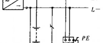
Grounding systems are divided into two large groups: with a solidly grounded neutral and with an isolated one. In the first type of circuit, the neutral conductor (denoted N) is always grounded and can be independent of the protective PE conductor, or can be connected to it to form a PEN conductor.
If the neutral wire is combined with a protective conductor, it forms a TN-C system, if carried out separately - a TN-S system, in the case when it is combined at a substation with a protective conductor, and at the entrance to the building it is divided into two conductors - protective PE and functional N , the TN-CS system is formed. Another type is a system in which the neutral conductor is grounded at the substation and three-phase current is supplied to the consumer through four wires, one of which is zero N. This is a TT system.
Application of the TN-C system
The TN-C system was widely used previously with the so-called two-wire network. In this case, there was no grounded contact in the sockets. In networks designed according to this system, the neutral wire was grounded, but if it broke, all devices remained energized. This forced the housing of each individual electrical appliance to be grounded. This system is not designed in modern buildings under construction. Only used in old buildings.
Application of the TN-S system
The TN-S system is more advanced, has a high degree of electrical safety, since it has a separate grounded conductor, but its cost is unreasonably high. With three-phase power, you have to lay five wires from the source - three phases, a neutral and a protective conductor PE.
To eliminate the shortcoming of the TN-S system, TN-CS was created. It provides one conductor PEN, which is a common wire grounded along the entire length from the power source to the entry into the building, and before entry it is divided into a neutral N and a protective conductor PE. This system also has a significant drawback. If the PEN conductor is damaged along the section from the substation to the building, all devices connected inside the building remain under dangerous voltage. For this system, the PUE (Electrical Installation Rules) require measures to provide additional protection for the PEN conductor from mechanical damage.
CT grounding type
The TT system is used to supply electricity outside the city and in rural areas through power lines installed on poles. Connecting electrical installations via this system is permitted only if it is impossible to ensure all electrical safety conditions in the TN system and avoid unjustified material costs. When contacting electrical appliances, protection against current must be carried out by turning off the power in the circuit. For this purpose, the rules prescribe special products - residual current devices - RCDs.
Requirements for grounding conductors
Well, having dealt with the main theoretical aspects, let's talk about the conductors themselves. Depending on where they are installed, completely different requirements are placed on them. Therefore, let's separately consider the inclusion of grounding wires for stationary and mobile electrical installations.
General requirements for grounding wires
But we will begin our conversation with the general requirements for conductors used for grounding. As you should already understand, they must ensure that the potential on the protected equipment is reduced to zero or close to it. In this regard, they must be able to pass a current equal to the short circuit current in a given electrical installation.
- It would seem that in this regard, the cross-section of such conductors must necessarily be no less than that of phase conductors, but this is not so. The fact is that phase conductors must ensure the long-term flow of large currents. But the protective wire should provide this opportunity only for the duration of the protection. Usually this time does not exceed 2-3 seconds.
- You can easily determine such a cross-section with your own hands thanks to Table 1.7.5 PUE. For wires with a cross-section of working conductors up to 16 mm 2, the cross-section of the protective conductors must be identical. For wires from 16 to 35 mm 2, the cross-section of the protective wires can be 16 mm 2. For wires with a larger cross-section, the protective conductor must be at least twice as small.
According to GOST standards, all cable and wire products must contain markings of the core cross-section. Moreover, if the cross-section of the grounding and grounding conductors differs from the working ones, then it should be indicated separately, as in the video.
- In some cases, a separate calculation of the cross-section of the grounding conductor is allowed. To do this, a formula is used that takes into account such indicators as short-circuit current, protection response time, type of insulation and conductor, as well as cable laying method. But this method of determining the cross-section is used quite rarely.
- Now, regarding the designation of grounding and neutral conductors. You already know their letter abbreviation. But in addition, they also have color. Grounding with a five-wire grounding system should have a yellow-green color. The neutral wire is indicated in blue.
- A separate issue is the quality of grounding. It is determined by measuring its resistance. According to clause 1.7.101 of the PUE for a three-phase network with a linear voltage of 380V, it should be no more than 4 Ohms. This is a fairly small value, which is determined only by the internal resistance of the conductor.
- To achieve adequate grounding quality, screw terminals should be used. They make it quite easy to disconnect the conductor for repair work and testing, and also provide high-quality contact. Extending the grounding and neutral conductors is not encouraged, but is allowed. In this case, you can use a ground wire socket clamp KS 066 1 or similar clamps for wires of smaller cross-section.
- A separate issue is the separate routing of grounding and grounding wires. According to clause 1.7.127 of the PUE, the copper wire for grounding must be at least 2.5 mm 2 if it has protection from mechanical damage and at least 4 mm 2 if it does not have it. For aluminum wire, regardless of the installation method, the cross-section must be at least 16 mm 2.
Requirements for portable grounding
Conductors for temporary use are a separate topic. With their help, temporary electrical installations are connected to the grounding circuit. These can be mobile booths, machinery or vehicles.
- For this purpose, special portable grounding connections are used. Such conductors are also used to create safe working conditions.
- Such conductors should not have insulation; this is done so that its integrity can always be visually inspected. To attach it to the ground loop and mechanism, it must have clamps. The clamp for the grounding wire must be attached to the wire by welding or screw connection.
- The conductor must be copper and stranded. Moreover, the number of broken individual wires is strictly regulated and should not exceed 5%.
- The cross-section of such portable groundings must be at least 16 mm 2 for electrical installations up to 1000V and at least 25 mm 2 for electrical installations at higher voltages. To ground machines and mechanisms, you can use a wire with a cross-section of at least 16 mm 2, regardless of the voltage class.
It is quite difficult to check the quality of such grounding. Therefore, the only condition is the mandatory cleaning of the metal surface before applying them.
vote
Article rating
Self-production
Making your own grounding is a sequential process consisting of several stages, each of which has its own characteristics. This does not require a pile of papers, since permission is not required in private construction. Installation should be carried out in the warm season, when the soil has thawed, dried out and settled.
To work you will need:
- welding machine;
- grinder, hammer drill;
- level, tape measure;
- pliers;
- shovel, sledgehammer;
- brush, paint;
- corrugated tube;
- aluminum tape.
The work is performed in the following sequence:
- Drawing up a project. Based on it, calculations of materials and equipment are carried out. You should make a small reserve, as errors are possible during the work process.
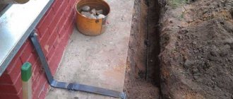
- Carrying out markings. The turf layer is carefully removed, then a pit of a given shape is torn off. The excavated material must be preserved, as it will be used for backfilling.
- From the middle of one side or from the corner, a flat trench is dug towards the building. It is needed for laying a cable or other current conductor between the frame and the electrical panel.
- The electrodes are cut out. Their ends are pointed for easier immersion into the soil. After this, the pins are driven into the ground at the corners of the trench. If a corner is used, holes are pre-drilled and the openings are filled with a mixture of earth and salt.
- The sides of the contour are cut out. They are connected to the electrodes and to each other. Welding areas are painted over.
- Near the ditch to the house, a bolt is welded to the frame. The cable is screwed to it. The joint is closed with a plastic bottle, the neck of which is sealed with aluminum tape.
- Entry into the house is made in the basement. To prevent chafing of the cable insulation, a flexible steel tube is inserted into the hole. The cable is pulled into it and connected to the shield.
- The final stage is filling the ditches with soil, leveling it and compacting it.
What is a ground loop
To understand what a loop grounding system is, you should imagine it as a system consisting of metal rods, strips connecting them and a set of copper connecting conductors. This prefabricated structure ensures reliable contact of the electrical installation’s current-conducting housing with the actual ground (soil).
When clarifying the question of what are grounding loops, it should be understood that their main component is a single electrode of a suitable size and cross-section, driven into the ground to a certain depth. To create a distributed loop system according to current technical requirements, a group of pins connected to each other by metal strips must be used.
1.7.61
When using the system, it is recommended to re-ground the PE
- and
PEN
conductors at the entrance to electrical installations of buildings, as well as in other accessible places. For re-grounding, natural grounding should be used first. The resistance of the re-grounding electrode is not standardized.
Inside large and multi-storey buildings, a similar function is performed by potential equalization by connecting the neutral protective conductor to the main ground bus.
Re-grounding of electrical installations with voltages up to 1 kV, receiving power via overhead lines, must be carried out in accordance with 1.7.102-1.7.103.
TN-CS and why you need to re-ground the PEN conductor
If we are talking about a populated area with one- and two-story buildings, then re-grounding the PEN conductor at the entrance to a private house according to the PUE is not required. And no 4, 10 or 30 ohms concern you. In normal mode, the re-grounding of the PEN conductor, which you will do yourself at the entrance to your house, essentially will not have any direct bearing on you. The resistance of its grounding device, together with all repeated groundings, will relate to the grounding of the transformer neutral, and this is the responsibility of the supplying organization.
Let's imagine that you have re-grounded with a grounding device resistance of 30 Ohms, and consider the option with a 300 Ohm charger. What's the difference here? For you, as the owner of a private home, no:
- When the general zero burns out, your efforts are practically useless.
- When the potential is transferred to grounded housings, the protective shutdown will work even without your re-grounding at the input.
Important! The only dangerous case that remains is when your PEN conductor burns out in the place before it separates into PE and N and the potential is carried out to neutralized housings. Here the situation is the same as with grounding in two-wire wiring. In this case, even if there is re-grounding, no RCD will operate. The only hope remains for a potential equalization system (EPS) and a voltage release for circuit breakers (or voltage control relays). And if you imagine that you have neither a release nor a control system in such an emergency situation, then it is better to re-ground the PE conductor with the lowest possible resistance of the grounding device to reduce the touch voltage.
Selecting the cable cross-section
The cable usually consists of 2-4 cores. The cross-section (more precisely, the cross-sectional area) of the core is determined by its diameter.
Based on practical considerations, at low current values, the cross-section of the copper conductor is taken to be at least 1 mm2, and for the aluminum conductor - 2 mm2. At sufficiently high currents, the wire cross-section is selected according to the connected power. It is usually assumed that a load of 1 kW requires a core cross-section of 1.57 mm2. From this follow the approximate values of the wire cross-sections, which should be followed when choosing its diameter. For aluminum - this is 5A per 1 mm2, for copper - 8A per 1 mm2. Simply put, if you have a 5 kW instantaneous water heater, then you need to connect it with a wire rated at least 25A, and for copper the cross-section should be at least 3.2 mm2.
Pixabay
Power cable AVVG: aluminum cores (1-4), cross-section from 2.5 to 50 mm2, polyvinyl chloride insulation, polyvinyl chloride sheath. Designed for installation in both dry and wet areas.
VVG power cable: copper cores (1-4), cross-section from 1 to 50 mm2, polyvinyl chloride insulation, polyvinyl chloride sheath. Used for laying in dry and damp areas.
Please note that from a number of preferred cross-sectional values (0.75; 1; 1.5; 2.5; 4; 6 mm2, etc.) for aluminum wires, the cross-section is chosen one step higher than for copper, since their conductivity is approximately 62% of the conductivity of copper. For example, if, according to calculations, a cross-sectional value of 2.5 mm2 is needed for copper, then for aluminum you should take 4 mm2, if for copper you need 4 mm2, then for aluminum - 6 mm2, etc.
Pixabay
Wires for internal power and lighting networks are often placed in protective corrugated plastic hoses.
VBBShv cable: copper polyvinyl chloride along the core, polyvinyl chloride sheath, armor made of galvanized steel strips, sealed outer hose. Can be used wherever there is a danger of mechanical damage to the wiring during operation.
In general, it is better to choose a cable for your home with a larger cross-section than required, in case you want to connect something else? In addition, it is necessary to check whether the cross-section of the wires is consistent with the maximum actual load, as well as with the current of the protective fuses or circuit breaker, which are usually located next to the meter.
So, you have finally decided on the material and cross-section. The next step is to select the brand of cable or wire.
1.7.76
The requirements for protection from indirect contact apply to:
1) housings of electrical machines, transformers, devices, lamps, etc.;
2) drives of electrical devices;
3) frames of distribution boards, control panels, panels and cabinets, as well as removable or opening parts, if the latter are equipped with electrical equipment with a voltage higher than 50 V AC or 120 V DC (in cases provided for by the relevant chapters of the PUE - higher than 25 V AC or 60 V VDC);
4) metal structures of switchgears, cable structures, cable couplings, shells and armor of control and power cables, sheaths of wires, sleeves and pipes of electrical wiring, shells and supporting structures of busbars (conductors), trays, boxes, strings, cables and strips on which reinforced cables and wires (except for strings, cables and strips along which cables with a neutralized or grounded metal sheath or armor are laid), as well as other metal structures on which electrical equipment is installed;
5) metal shells and armor of control and power cables and wires for voltages not exceeding those specified in 1.7.53, laid on common metal structures, including in common pipes, boxes, trays, etc., with cables and wires on higher voltages;
6) metal cases of mobile and portable electrical receivers;
7) electrical equipment installed on moving parts of machines, machines and mechanisms.
When automatic power shutdown is used as a protective measure, the specified exposed conductive parts must be connected to the solidly grounded neutral of the power source in the system and grounded in systems and.
1.7.102
At the ends of overhead lines or branches from them with a length of more than 200 m, as well as at the inputs of overhead lines to electrical installations in which automatic power off is used as a protective measure in case of indirect contact, repeated PEN
- conductor. In this case, first of all, natural grounding devices should be used, for example, underground parts of supports, as well as grounding devices intended for lightning overvoltages (see Chapter 2.4).
The specified repeated groundings are performed if more frequent groundings are not required under the conditions of protection against lightning surges.
Re-grounding PEN
-conductors in DC networks must be made using separate artificial grounding conductors, which should not have metal connections to underground pipelines.
Grounding conductors for re-grounding PEN
- the conductor must have dimensions no less than those given in Table 1.7.4.
Grounding system terms
Before moving on to considering the rules for installing grounding, it is necessary to define the terms used by specialists when carrying out this type of work.
- Firstly, what is a grounding device? This is a structure consisting of a grounding conductor and grounding conductors.
- Secondly, what is a ground electrode? This is a metal conductor that is directly connected to the ground.
- Third, what are grounding conductors? This is a system of metal conductors that connect the ground electrode to electrical equipment.
Please note that grounding an electrical installation artificially is called intentional. There is such a thing as the resistance of a grounding device. This is, in fact, the sum of the resistances of the grounding conductor and grounding conductors. If we talk about the resistance of the ground electrode itself, then this is the voltage relative to the ground to the current passing through the metal conductor.
It is strongly recommended that the installation of the ground loop be done with reference to the PUE standards. This approach will allow you to make all the necessary connections and connect the circuit correctly in compliance with all standards. This will ensure reliable operation of the protection system in the building, preventing the negative consequences of natural or anthropogenic factors. To make a ground loop with your own hands, you should have some knowledge in the field of electrical engineering. Before work, it is recommended to read the necessary literature, as well as sections of the PUE that refer to the installation of the ground loop.
According to the current Rules for Electrical Installations, the secondary circuit must be located at the exit points of any type of building. Natural grounding conductors should be installed in place of the repeated grounding loop. The rules specify some metal structure trimmers that are suitable for grounding. Among them you can find reinforced concrete structures, massive metal parts that must come into contact with the ground with most of their surface. If the circuit is connected in an aggressive environment, then such structures must have a special protective coating. Also suitable for a grounding element are a metal water pipe that is dug deep into the ground, or long rails from non-electrified railways.
You must definitely pay attention to the PUE clause, which indicates elements that cannot be used as a ground loop. These include reinforced concrete structures with metal elements that are energized, as well as pipelines with flammable substances, heating and sewer pipes. If the circuit must be made using a natural grounding device (soil, foundation under a building), then you must first make theoretical calculations and a connection diagram.
Typically, during the construction of a new building, the ground loop is made artificially by burying supports underground. This method is considered more universal and is used much more often in practice. This is dictated by the fact that not all places have suitable conditions for natural grounding.
A very important factor that influences the circuit is soil resistance. So in places with high soil moisture, the resistance will be low. Significant installation problems arise on dry soil. For example, sandy soils, rocky or stone formations are completely unsuitable for such work. The regulatory documents indicate the exact resistance value that determines the level of current flow, as well as what resistance the circuit should have.
There are two types of grounding used in household electrical installations.
Traditional ground loop. In this case, the main grounding element must be made of several vertical supports and one horizontal one. They must have a round cross-section and be smooth. To do this, you can use steel rods, pipes or thick reinforcement. For ordinary private houses, it is advisable to use large-sized supports. If steel reinforcement is used, then you can take 3 such elements with dimensions starting from 2 meters. They are set so that an equilateral triangle is formed if the installation location of the reinforcement is at the vertices of the conventional figure. Before you begin installing the supports, you need to measure the distance between them. The more space between them, the better. It is desirable that the distance between the grounding elements be at least 1.5 meters. After making sure that the measurements correspond to the norm, you can begin installing the circuit.
When the elements are driven into the ground, a reliable connection should be made between them. Can be attached with separate fasteners at the same height. The connection of all supports is made using horizontal grounding conductors closer to the top of the electrodes. According to PUE standards, connections must be made of steel or copper. Each element can be connected to the transverse electrode by welding. This method is more reliable than movable fasteners (nuts, bolts). As for the sizes of these electrodes, they have standardized smallest values. When installing, preference should be given to longer supports. Their thickness is regulated by the rules for electrical installations in Table 1.7.4.