Updated: 04/23/2021 12:51:22
Expert: Konstantin Borisovich Polyakov
When designing electrical networks of various levels of complexity (including not only the number of end consumers, but their electrical characteristics), developers are faced with the need to automate the opening and closing of the circuit. Fortunately, there is no shortage of suitable devices. On the market you can find dozens of models of relays and contacts, designed for both low- and high-current systems.
But therein lies the problem. It is not always obvious which specific device for opening or closing the electrical network is best to use. And if everything is clear in terms of electrical parameters, the principle of operation is not so obvious.
And therefore, in this material we will look at how a relay differs from a contactor, the features of their use and the fundamental differences between the two categories of devices.
Features of networks with different inductance levels
One of the most important problems that need to be solved when designing electrical networks is arc discharges on key contacts. They can occur even at home - for example, when you plug in a low-quality charger for a smartphone or laptop, you can see a tiny short-term flash. This is called an arc discharge.
Arc discharges (electric arcs) are characterized by significant voltage due to the potential difference on the sides. In this case, the current strength can be quite insignificant. For example, arc discharges can be observed when combing long hair with combs made of synthetic materials - and the “sparks” that escape are definitely not capable of killing a person. Moreover, their voltage can be tens of thousands of volts.
Electric arcs that occur at the contacts of keys (switches, relays, even sockets) have a similar nature, but are much more destructive. Because they instantly raise the temperature of the surface on which they occur, they can simply melt the metal. In fact, that is why they are used in welding.
In addition, according to the Joule-Lenz law, when an electric arc occurs, the current strength increases significantly. Essentially, there is something like a short circuit, but it does not (in the short term) cause damage to devices or the circuit.
In alternating current networks, arc discharges occur primarily due to induction. More precisely, when connecting end consumers with significant inductance. This is due to several physical laws, including even the formation of reactive currents.
In electrical networks in which end consumers with a high level of inductance are installed, the use of relays is impractical and even dangerous. The classic mechanism of this key simply involves connecting two contacts to form a circuit - by time, by command, by temperature or due to other external factors, depending on the type and purpose of the device. But, in any case, such a switching mechanism leads to the formation of an arc. And it, in turn, is characterized by a high danger for the relay itself.
What is the difference between a starter and a contactor according to GOST and rules.
Even among professional electricians, heated debates often arise about which switching device is considered a starter and which is a contactor.
Those who are not particularly knowledgeable are simply called launchers. What can we say about ordinary consumers who may encounter these devices only a couple of times in their entire lives.
Some people mistakenly look first at the arc chutes, thinking that if they are there, then there is a contactor in front of them.
Allegedly, they are needed to dampen currents, starting from the 5th magnitude. The fifth value is a current equal to I=100A.
At the same time, thinking that the starter is designed only for low currents (up to 100A).
Supporters of this classification even came up with their own gradation:
- relays are devices for low currents
- starters – for medium
- contactors – for high currents
All this is of course not true.
One fairly popular brand, namely PML, is most likely to blame for such misconceptions. For these models, starters are designed for currents from 10 to 100A, and contactors from 10 to 800A. This is where the confusion started.
Allegedly, if the device is more than 100A, then it belongs to the contactors. Some packages even contain seemingly opposite messages. On one side it says:
- PM – magnetic starter
And then on the other:
What should we believe and what do the rules and documentation say about this? To understand this, first of all, let’s find the definitions of these devices and see what the differences are.
When is it appropriate to use a relay?
Do not think that classic relays are intended for use exclusively in low-current (domestic or some industrial) lines. These devices perform well in various conditions. For example, in aviation, relays are often used that switch direct electric currents with a power of hundreds of amperes.
The main feature of these electromechanical devices is that they are not designed for arc discharge. Their contacts can be physically damaged when this effect occurs, which leads to loss of functionality and other negative consequences - up to a short circuit or destruction of the final equipment.
Relays are well suited for switching secondary circuits that include end consumers with low inductance. For example, lamps and lighting systems, alarms, low-power electrical appliances. It is ideal if the connected equipment, in principle, does not contain electric motors or other functional elements characterized by a significant level of induction.
At the same time, voltage and current do not matter. There are low-current relays, used for use in household networks, and high-current, focused on switching direct electric currents with a large number of amperes. The main thing is precisely the question of induction and, as a consequence, the formation of “sparks”.
By the way, power supplies that convert alternating current into direct current with a decrease in voltage and power are devices with relatively significant induction. Therefore, it is better not to use a relay to switch them. And because of this, they sometimes “spark” when plugged into an outlet.
What is a relay?
Relays are switches designed to control circuits using low power electrical signals. It acts as a link between the electrical circuit that needs to be controlled and the circuits that control it. By using a relay, galvanic isolation between the control and controlled circuits is maintained.
The relay works in such a way that it has two sides, namely primary and secondary. In the primary side there is a coil fed by a low-power source of direct or alternating current, which is nothing more than a control signal. While the secondary side forms a connection to the load that needs to be controlled (fans, pumps, lamps, compressors and other electrical appliances).
An electromagnetic coil creates a magnetic field when current passes through it. Using a spring, the armature is connected to the end of the coil and is attracted to it when power is applied to the coil. When the coil is de-energized, the armature assumes its normal position. Thus, the circuit is closed or opened (depending on the type of contact - normally open or normally closed), and the load receives electrical energy and operates accordingly.
When is it appropriate to use contactors?
Contactors are designed for switching alternating current networks into which consumers with high inductance are connected. They are not resistant to arc discharge, but try in every possible way to avoid its occurrence. To do this, they are equipped with additional protective components of various types, one or more:
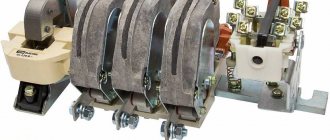
- Arcing chambers. These are special grilles that neutralize “sparks”. The arc, passing between the metal plates, increases its length - and thereby cools down until it is completely extinguished;
- Mechanically moving contacts suitable for active switching. Most contactors for domestic and industrial use are oriented at switching frequencies from 30 to 3600 actions (on-off cycles) per hour;
- Separate control circuit. An auxiliary electric current circulates in it, having a significantly lower voltage than in the main one.
Thanks to all these design and technological features, contactors are suitable for controlling networks with connected consumers of significant inductance - from household equipment with electric motors (refrigerators, washing machines, fans) to industrial machines.
In addition, it is worth noting that equipment with electric motors tend to consume significantly higher currents at start-up than during operation. When the engine starts, the power spikes - as does the power (in amperes) - which overloads the line. Often relays designed for use in low-current networks cannot withstand such overloads. There are no such problems with contactors.
Similarly, you should not think that a contactor is a device for use in high-current networks. There are models aimed at domestic use. For example, on the market you can find contactors rated for a nominal voltage of 230 volts and a current of 10 amperes. In this case, their coils are connected to the 110-volt auxiliary circuits.
What is a contactor?
An electrical device designed to frequently switch on/off power electrical circuits is known as a contactor. Power circuits are controlled by contactors with durable contacts, which ensures their safe switching on/off.
Similar to the operation of relays, contactors are controlled by a coil (solenoid). However, unlike a relay, it has an arc-extinguishing chamber that extinguishes the arc formed when the contacts break under load. In contactors, due to the attraction of the armature, the moving contact forms a connection with the fixed contact. However, after de-energizing the control coil, the loss of the armature separates the moving contact and the fixed contact.
It should be noted here that in the open state of the magnet (armature), there is a large air gap, so the reactance is low. Once the coil is energized, it draws a large current, which causes the armature to retract, reducing the air gap. This increases the reactance and reduces the coil current. In this case, the coil current drops to the level of the magnetizing current, which keeps the contactor in the closed state overcoming the spring force.
Comparison of relays and contactors
So, let’s summarize by comparing these two types of devices for switching electrical networks.
| Characteristic | Relay | Contactor |
| Arc protection | No | Yes |
| Use in circuits with consumers with high inductance | No | Yes |
| Application in high-current electrical networks | Mainly at constant current | Yes |
| Application in low-current electrical networks | Yes | Yes |
| Design Features | No | Equipped with arc chutes and/or other arc flash protection solutions |
| Main areas of use | Switching of low-current systems - lighting, alarm | Switching systems with high inductance equipment - in production and in workshops |
If you plan to connect equipment that consumes high currents at startup or is characterized by high inductance and/or the creation of reactive voltage during operation, it is advisable to use contactors. In other cases, a relay will suffice.
Conclusion
Therefore, we can say that relays are suitable for "single phase supply" circuits and are therefore used in automation and protection circuits such as motor control, electric pumps and other control circuits. Although contactors are suitable for three-phase networks, they are often used to control power to induction motors, transformers, capacitor banks (variance factor compensators) and other electrical power circuits.
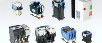
220 V starter control circuit
One wise man said: there are 44 schemes for connecting buttons to a magnetic starter, of which 3 work, and the rest do not. But there is only one correct one. Let's talk about it (see diagram below).
It is better to leave connecting the power circuits for later. This will make it easier to access the coil screws, which are always covered by the main circuit wires. To power the control circuits, we use one of the phase contacts, from which we send a conductor to one of the terminals of the “Stop” button.
This can be either a conductor or a cable core.
Two wires will go from the stop button: one to the “Start” button, the second to the block contact of the starter.
To do this, a jumper is placed between the buttons, and a cable core to the starter is added to one of them at the point where it is connected. There are also two wires from the second terminal of the “Start” button: one to the second terminal of the block contact, the second to terminal “A1” of the control coil.
When connecting buttons with a cable, the jumper is already placed on the starter, and the third core is connected to it. The second output from the coil (A2) is connected to the zero terminal. In principle, there is no difference in what order you connect the outputs of the buttons and the block contact. It is advisable to connect only the “A2” terminal of the control coil to the neutral conductor. Any electrician expects that zero potential will only be there.
Orlov Anatoly Vladimirovich
Head of the Relay Protection and Automation Service of Novgorod Electric Networks
Ask a Question
Now you can connect the wires or cables of the power circuit, not forgetting that next to one of them at the input there is a wire to the control circuit. And only from this side is power supplied to the starter (traditionally - from above). Trying to connect buttons to the starter output will lead to nothing.
Connecting a thermal relay to the starter circuit
The thermal relay is used to protect the electric motor from overload. Of course, it is still protected by an automatic switch, but its thermal element is not enough for this purpose. And it cannot be adjusted exactly to the rated current of the motor. The operating principle of a thermal relay is the same as in a circuit breaker.
The current passes through the heating elements; if its value exceeds the specified value, the bimetallic plate bends and switches the contacts.
This is another difference from a circuit breaker: the thermal relay itself does not turn off anything. It simply gives a signal to turn off. Which needs to be used correctly.
The power contacts of the thermal relay allow you to connect it to the starter directly, without wires. To achieve this, each product range complements each other. For example, IEK produces thermal relays for its starters, ABB produces its own. And so it is with every manufacturer. But products from different companies do not fit together.
Thermal relays can also have two independent contacts: normally closed and normally open. We will need a closed one - as in the case of the “Stop” button. Moreover, functionally it will work the same way as this button: breaking the power supply circuit of the starter coil so that it falls off.
Now you need to embed the found contacts into the control circuit. In theory this can be done almost anywhere, but traditionally it is connected after the coil.
In the case described above, this will require sending a wire from pin “A2” to the contact of the thermal relay, and from its second contact to the place where the conductor was previously connected. In the case of control from 220 V, this is the zero bus; with 380 V, this is the phase on the starter. The thermal relay is not noticeable in most models.
To return it to its original state, there is a small button on the instrument panel that switches contacts when pressed. But this should not be done immediately, but let the relay cool down, otherwise the contacts will not engage. Before putting it into operation after installation, it is better to press the button, eliminating possible switching of the contact system during transportation due to shaking and vibration.
Interesting video about the operation of a magnetic starter:
Magnetic switch
Now about what you should pay attention to when examining the starter itself before connecting it. The most important thing is the voltage of the control coil, which is indicated either on it itself or nearby. If the inscription reads 220 V AC (or there is an AC icon next to 220), then a phase and a zero are required for the control circuit to operate.
Watch an interesting video about the operation of a magnetic starter below:
If it is 380 V AC (the same alternating current), then the starter will be controlled by two phases. In the process of describing the operation of the control circuit, it will become clear what the difference is.
With any other voltage values, the presence of a direct current sign or the letters DC, it will not be possible to connect the product to the network. It is intended for other circuits.
We will also need to use an additional contact of the starter, called a block contact. For most devices, it is marked with the numbers 13NO (13NO, simply 13) and 14NO (14NO, 14).
Orlov Anatoly Vladimirovich
Head of the Relay Protection and Automation Service of Novgorod Electric Networks
Ask a Question
The letters NO mean “normally open”, that is, it closes only when the starter is pulled in, which can be checked with a multimeter if desired. There are starters that have normally closed additional contacts; they are not suitable for the control circuit under consideration.
Power contacts are designed to connect the load, which they control.
Their markings vary from manufacturer to manufacturer, but there are no difficulties in identifying them. So, we attach the starter to the surface or DIN rail in the place of its permanent location, lay the power and control cables, and begin the connection.
Time delay relay 220V
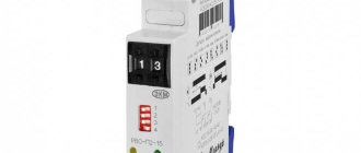
A device whose purpose of operation is to create conditions where electrical circuit devices operate in a certain sequence is called a time relay. For example, if you need to create a load switching mode not immediately upon arrival of a control signal, but after a set period, a certain system is used. The following types of equipment are distinguished:
- Time relay 220V electronic type. They can provide time exposure within fractions of seconds and up to several thousand hours. They can be programmed. The energy consumption of such devices is insignificant, and the dimensions are small.
- With deceleration time on the electromagnet for DC supply circuits. The circuit is based on two electromagnetic coils, in which magnetic fluxes simultaneously arise, directed in the opposite direction and thus weakening each other for the duration of the response delay.
- Devices where the response time is slowed down by a pneumatic process. The shutter speed can be within 0.40-180.00 seconds. The response delay of the pneumatic damper is carried out by adjusting the air intake.
- Devices on an anchor mechanism or a clock circuit.