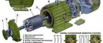
Starting an asynchronous motor
Starting properties of engines .
When starting, the engine rotor, overcoming the load torque and moment of inertia, accelerates from rotation speed n = 0 to n . In this case, the slip changes from s p = 1 to s . When starting, two basic requirements must be met: the torque must exceed the moment of resistance ( Mvr>Ms ) and the starting current I p must be as small as possible.
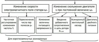
Depending on the design of the rotor (short-circuit or phase), motor power, and the nature of the load, various starting methods are possible: direct starting, starting using additional resistances, starting at reduced voltage, etc. Below, various starting methods are discussed in more detail.
Direct start.
Starting a motor by directly connecting the stator winding to mains voltage is called direct starting. The direct start circuit is shown in Fig. 3.22. When the switch is turned on at the first moment, slip s = l , and the reduced current in the rotor and the stator current equal to it
, (3.37)
are maximum (see paragraph 3.19 at s=1). As the rotor accelerates, the slip decreases and therefore at the end of the start the current is significantly less than at the first moment. In serial motors with direct starting, the multiplicity of the starting current is kI = IP / I1NOM = ( 5,..., 7), with a larger value referring to motors of higher power.
Rice. 3.22
The starting torque value is found from (3.23) at s = 1:
,(3.38)
From Fig. 3.18 it can be seen that the starting torque is close to the nominal and significantly less than the critical one. For serial engines, the starting torque multiplicity is MP/MNOM = (1.0,…,1.8).
The data shown shows that during direct starting, a current surge occurs in the network supplying the motor, which can cause such a significant voltage drop that other motors powered from this network may stop.
On the other hand, due to the small starting torque when starting under load, the engine may not overcome the moment of resistance on the shaft and will not move. Due to these disadvantages, direct starting can only be used for low and medium power motors (up to approximately 50 kW).
Starting engines with improved starting properties.
Improving the starting properties of asynchronous motors is achieved by using the effect of current displacement in the rotor due to the special design of the squirrel cage. The effect of current displacement is as follows: the flux linkage and inductive reactance X2 of the conductors in the rotor slot are higher, the closer to the bottom of the slot they are located (Fig. 3.23). Also X2 is directly proportional to the frequency of the rotor current.
Consequently, when starting the engine, when s = 1 and f2 = f1 = 50 Hz, inductive reactance X2 = max and under the influence of this, the current is forced into the outer layer of the groove. The current density j along the h coordinate is distributed along the curve shown in Fig. 3.24. As a result, the current mainly passes through the outer section of the conductor, i.e. over a significantly smaller cross-section of the rod, and, consequently, the active resistance of the rotor winding R2 is much greater than during normal operation. Due to this, the starting current decreases and the starting torque of the MP increases (see (3.37), (3.38)).
As the engine accelerates, the slip and frequency of the rotor current drops and by the end of the start reaches 1 - 4 Hz. At this frequency, the inductive reactance is small and the current is distributed evenly over the entire cross-section of the conductor. With a strongly pronounced current displacement effect, direct starting becomes possible with lower current surges and higher starting torques.
Engines with improved starting properties include engines with deep slot rotors, double squirrel cage rotors, and some others.
Fig.3.23 Fig. 3.24
Motors with deep slots.
As shown in Fig. 3.25, the rotor groove is made in the form of a narrow slot, the depth of which is approximately 10 times greater than its width. The winding in the form of narrow copper strips is placed in these slot-slots. The magnetic flux distribution shows that the inductance and inductive reactance at the bottom of the conductor are significantly greater than at the top.
Fig.3.25
Therefore, when starting, the current is forced into the upper part of the rod and the active resistance increases significantly. As the engine accelerates, the slip decreases, and the current density across the cross section becomes almost the same.
In order to increase the effect of current displacement, deep grooves are made not only in the form of a slot, but also in a trapezoidal shape. In this case, the depth of the groove is slightly less than with a rectangular shape.
Double cage engines.
In such motors, the rotor windings are made in the form of two cages (Fig. 3.26): in the outer slots 1 there is a winding made of brass conductors, in the inner slots 2 there is a winding made of copper conductors.
Fig.3.26
Thus, the outer winding has a higher active resistance than the inner one. When starting, the outer winding is coupled to a very weak magnetic flux, and the inner winding is coupled to a relatively strong field. As a result, the current is forced into the outer cell, and there is almost no current in the inner cell.
As the engine accelerates, the current from the outer cage passes into the inner cage and, at s = sNOM, flows mainly through the inner cage. The current in the outer cage is relatively small.
The resulting starting torque, which is the sum of the torques from the two cages, is significantly greater than that of motors of normal design, and somewhat greater than that of motors with a deep slot. However, it should be kept in mind that the cost of motors with a double cage rotor is higher.
Start by switching the stator winding.
If during normal operation of the engine the stator phases are connected in a triangle, then, as shown in Fig. 3.27, during startup they are initially connected in a star.
Fig.3.27
To do this, switch Q is first turned on, and then switch S is placed in the lower Start position. In this position, the ends of the phases X, Y, Z are connected to each other, i.e. the phases are connected in a star. In this case, the phase voltage is √3 times less than linear.
As a result, the line current at start-up is 3 times less than with a delta connection. When the rotor accelerates at the end of the start, switch S is moved to the upper position and, as can be seen from Fig. 3.27, the stator phases are reconnected into a triangle.
The disadvantage of this method is that the starting torque is also reduced by 3 times, since the torque is proportional to the square of the phase voltage, which is √3 times less when the phases are connected by a star. Therefore, this method is applicable for small load torques and only for motors that operate normally when the stator windings are connected in a triangle.
Start when additional resistors are connected to the stator circuit (Fig. 3.28)
Fig.3.28
Before starting, the switch (starter) is in the open state and switch Q1 is closed.
In this case, additional resistors RDOB are included in the stator circuit. As a result, the stator winding is supplied with a reduced voltage U1n = U1NOM – InRDOB. After the engine accelerates, switch Q2 closes and the stator winding is switched on to the rated voltage U1NOM. By selecting RDOB you can limit the starting current to the permissible one.
It should be borne in mind that the starting torque, proportional to U21P, will be less and is (U1P / U1NOM)2 nominal. It is important to note that with this starting method, losses in resistance RDOB (RDOBI21n) are significant. Instead of resistors RDOB, it is possible to include coils with inductive reactance HDOB close to RDOB.
The use of coils makes it possible to reduce losses in starting resistance.
Autotransformer starting.
In addition to these methods, you can use the so-called autotransformer starting.
The corresponding diagram is shown in Fig. 3.29.
Fig.3.29
Before starting, switch S is set to position 1, and then the autotransformer is turned on and the stator is supplied with reduced voltage U1P. The engine accelerates at reduced voltage and at the end of acceleration, switch S is moved to position 2 and the stator is supplied with rated voltage U1nom.
If the transformation ratio of the step-down transformer is n , then the current I at its input will be n times less. In addition, the starting current will also be n times less, i.e. the current when starting in the network will be n2 times less than when starting directly.
This method, although better than those discussed in paragraph 3.14.7, is much more expensive.
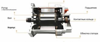
Starting a motor with a wound rotor.
Starting a wound-rotor motor is carried out by connecting a starting rheostat to the rotor circuit, as shown in Fig. 3.30.
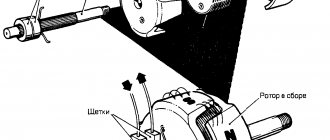
The beginnings of the phases of the rotor windings are connected to slip rings and connected through brushes to a starting rheostat with resistance Rp.
The starting rheostat resistance Rp is calculated so that the starting torque is maximum, i.e. equal to critical. Since at start-up the slip is sП = 1, then sП = 1 = sК, the equality MP = M Pmax = MK will be ensured. Then
.
The engine starts according to the curve shown in Fig. 3.31. At the moment of start-up, the operating point on the mechanical characteristic is in position a , and when the engine accelerates, it moves along curve 1, corresponding to a fully turned on rheostat.
At the moment corresponding to point e, the first stage of the rheostat is turned on and the moment increases abruptly to point b - the engine operating point moves to curve 2; at the moment of time corresponding to point d, the second stage of the rheostat is turned off, the operating point jumps to point c and the engine reaches natural characteristic 3 and then to point f. The rheostat is short-circuited, the rotor winding is short-circuited, and the brushes are retracted from the rings.
Thus, the wound rotor makes it possible to run high-power asynchronous motors with limited starting current. However, this starting method is associated with significant losses in the starting rheostat.
In addition, a wound-rotor motor is more expensive than a squirrel-cage motor. Therefore, a wound-rotor motor is used only for high power and high drive requirements.
Specifications
The basic requirements that ensure high-quality operation of asynchronous units with a wound rotor are defined and specified in the relevant GOSTs.
They determine the main technical characteristics and these parameters include:
- Dimensions and engine power , which must have indicators that comply with technical regulations.
- The level of protection must correspond to the conditions in which the operation process takes place, since different types of machines can be designed for installation outdoors or only indoors.
- High degree of insulation , which must be resistant to increased operating temperature and subsequent heating.
- Different types of asynchronous motors are designed for use in certain climate conditions. This applies primarily to the installation of such machines in extremely cold areas or, conversely, hot areas. The design of the unit must correspond to the climate of the area in which the operation process takes place.
- Full compliance with operating modes.
- Availability of a cooling system , which must correspond to the operating conditions of the machine.
- The noise level when starting the unit at idle speed must correspond to the second class or be lower than it.
How to find out the starting current?
The starting current multiplicity (the ratio of the starting current to the rated current) is not so easy to find in the engine documentation. But you can measure (evaluate, find out) yourself. Here are a few ways off the top of your head:
Of course, reality is different from experiment. First of all, the short circuit current of a real power supply network is not infinite. That is, the wires supplying the engine have a resistance at which the voltage drops at the moment of starting (sometimes by up to 50%). Because of this limitation, the actual starting current will be less and acceleration will take longer. Therefore, you need to understand that the value of the starting current multiplier specified by the manufacturer will always be less in reality.
What are engines for - to power machinery and make a profit!
Now let's look at another question -
Thermal effect of starting current
If we move on to the formulas, the starting current has a thermal effect on the electric motor, which is described by the so-called Joule integral. Simply put, the thermal energy produced by an electric current is proportional to the square of the current multiplied by the time. This quantity is denoted by I2t.
The good news is that the circuit breaker has approximately the same thermal (time-current) characteristic as the time-current characteristic of motor acceleration.
Time-current characteristics of the circuit breaker
What do we see? To protect the engine, automatic machines with characteristic D are mainly used, precisely in order to react less to short-term overloads. Read more here.
And for the motor starting current the graph will be something like this:
Starting current graph (theoretical) at Kp = 6
The linearity of the graph is conditional. It all depends on the change in load torque during acceleration. The theoretical graph is shown with a dotted line. On this graph Kp = Ip / In = 6, but this is a theoretical (tabular) value. Acceleration time to nominal = tп.
The actual graph is drawn with a solid line. On it Iп` is the real value of the starting current, which is always less than the theoretical one. This is due to the fact that the supply network has non-zero resistance, and as the current increases, voltage losses occur on the wires.
I wrote about losses at low voltage here, and about losses in 0.4 kV networks here.
It is clear that due to losses, the acceleration time will be longer; it is indicated on the graph by tп`.
Now let's rotate the last graph to bring the axes to the same coordinate system:
Time from current, so to speak
Isn’t it very similar to the time-current characteristic of a protective motor?
It turns out that both characteristics compensate each other, and when choosing a machine, it is enough to adjust its setting to the rated current of the motor. For particularly difficult starts, when the area under the motor starting curve is greater than the area under the curve of the circuit breaker, it is worth thinking about a soft start - soft starter or inverter.
What is the harm from inrush current?
Inrush current is a problem. This -
The starting current overloads everything, and the moment of starting becomes a burden to all participants in the process. It is at this critical moment that a “weak link” may appear. In addition, many power participants operating on this network experience problems - for example, light bulbs dim due to low voltage, and controllers can freeze due to strong interference.
And at the same time, starting current is a problem that cannot be avoided if you immediately supply the motor with rated power and do not use special methods.
Real current measurements
As I said above, in my opinion the best way to “see” the inrush current is to use an active (resistive) shunt and look at the voltage on it with an oscilloscope.
I use this shunt:
Shunt for measuring inrush current using an oscilloscope
The subject is a geared motor that turns a vertical auger through a chain transmission:
Geared motor on which we measure the starting current
The auger was full at the time of start-up, so its operating current (7.7 A, measured with clamps) was almost equal to the rated current (8.9 A, visible on the nameplate).
Vertical auger motor nameplate
The inrush current situation is visible on the oscilloscope:
Inrush current waveform 500 ms/div
Let's bring the moment of interest closer by accelerating the scan to 100 ms/div:
Inrush current waveform 100 ms/div
Here it is already easy to see the sine of the supply current and estimate the multiplicity factor of the starting current Kp, which is approximately equal to 4.
Let's bring the moment of truth even closer (up to 50 ms/div):
Motor starting moment – starting current
Here the transient processes caused by the inductance and self-inductive emf of the motor windings are already clearly visible. This pulse, the duration of which is much less than the network period of 20 ms, provides good interference with a wide spectrum into the power supply network and radio air.
Another reason to use an inverter? Not really, the situation with interference there is much worse!